
Blogs
The latest news about Dell PowerStore releases and updates

When Performance Testing Your Storage, Avoid Zeros!

Tue, 20 Feb 2024 17:37:42 -0000
|Read Time: 0 minutes
Storage benchmarking
Occasionally, Dell Technologies customers will want to run their own storage performance tests to ensure that their storage can meet the demands of their workload. Dell Technologies partners like Microsoft publish guidance on how to use benchmarking tools such as Diskspd to test various workloads. When running these tools on intelligent storage appliances like those offered by Dell Technologies, don’t forget to watch for how your test files are populated!
The first step in using performance benchmark tools is creating one or more test files for use when testing. The benchmark tool will then write and read data to and from these files, taking measurements to assess performance. An important detail that is often overlooked is how the test files are populated with data. If the files are not populated correctly, it can lead to misleading results and inaccurate conclusions.
We’ll use Diskspd as an example, however please note that most tools have the same default behavior. By default, when you run a Diskspd test, you need to specify several parameters, such as a test file location and size, IO block size, read/write ratio, queue depth, and so on.
If we open a test file created with default parameters and examine it with a hexadecimal editor, this is what it looks like:
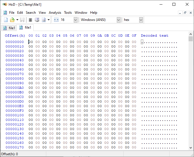
It is filled with nothing, 0x00 throughout the entire file – all “zeros”!
OK, so what is the problem?
When storage benchmarking tools create test files, they all use synthetic data for testing. This is fine when performing IO to a storage device with no “intelligence” built in because it will perform unaltered IO directly to the storage without the data content mattering. In the past, storage devices were simple and would read and write data as commanded, so the data content was irrelevant.
However, intelligent storage appliances such as those offered by Dell Technologies look at data differently. These products are built for efficiency and performance. Compression, deduplication, zero detection, and other optimizations may be used for space savings and performance. Since an empty file would obviously compress and deduplicate well, most of this IO will not access the disks in the same manner that a file of actual data would. It is also possible that other components in the data path would behave differently than normal when repeatedly presented with an identical piece of data.
It is safe to assume that these optimizations likely exist on data being stored in the cloud as well. Many cloud providers use intelligent storage appliances or have developed proprietary software to optimize storage.
The bottom line is that your test is likely inaccurate and may not represent your storage performance under more realistic conditions. While no synthetic test can reproduce a real workload 100%, you should try to make it as realistic as possible.
Mitigations
Some tools can initialize the test files with random data. Diskspd, for example, has parameters that can be added to create a buffer of random data to be used to write to the files or specify a source file of data. Regardless of the method used, you should inspect the test files to make sure that at a minimum, random data is being used. Zero-filled files and repeating patterns should be avoided.
Random data also may not achieve the expected behavior when compression and deduplication capabilities are used. More advanced testing tools such as vdbench can use target compression and deduplication capabilities independently.
Tips
Here are a few more tips when benchmarking storage performance to try to make it as realistic as possible:
- Use datasets of comparable size to real data workloads. Smaller datasets may fit entirely in the cache and skew results.
- Use IO sizes and read/write ratios that match your workload. If you are unsure of what your workload looks like, your Dell Technologies representative can assist you.
- Test with “multiples”. Intelligent storage assumes multiple files, volumes, and hosts. At a minimum, use multiple files and volumes. When testing larger block sizes, you may need to use multiple hosts and multiple host bus adapters to generate enough IO to test the full bandwidth capabilities of the storage.
- Start with a light load and scale up. Begin with one file, one worker thread, and a queue depth of one. In general, modern storage is designed for concurrency. Some amount of concurrency will be required to fully use storage system resources. As you scale up, observe the behavior. Pay attention to the measured latency. At some point as you scale the test, latency will start to increase rapidly.
- Excessive latency indicates a bottleneck. Once latencies are excessive, you have encountered a bottleneck somewhere. “Excessive” is a relative term when it comes to storage latency and is determined by your workload and business needs. Only scale the test to the point where the measured latency is within your acceptable range or above. Further increasing the test load will result in diminishing returns.
- Make sure the entire test environment can drive the wanted performance. The storage network and host configuration must be capable of desired performance levels and configured properly.
- Beware of outdated guidance. There are still articles online that are over a decade old that reference testing methods and best practices that were developed when storage was based on spinning disks. Those assumptions may be inaccurate on the latest storage devices and storage network protocols.
Summary
Storage performance benchmarking can be interesting and provide useful data points. That said, what is most important is how the storage supports actual business workloads and—most importantly—your unique workload. As such, there is no true substitute for testing with your actual workload.
Selecting the proper storage fit for your environment can be challenging, and Dell Technologies has the expertise to help. Leveraging tools like CloudIQ and LiveOptics, Dell Technologies can help you analyze your storage performance, explain storage metrics, and make recommendations to increase storage efficiency.
Author: Doug Bernhardt, Sr. Principal Engineering Technologist | LinkedIn

PowerStore validation with Microsoft Azure Arc-enabled data services updated to 1.25.0
Mon, 12 Feb 2024 20:04:34 -0000
|Read Time: 0 minutes
Microsoft Azure Arc-enabled data services allow you to run Azure data services on-premises, at the edge, or in the cloud. Arc-enabled data services align with Dell Technologies’ vision, by allowing you to run traditional SQL Server workloads on Kubernetes, on your infrastructure of choice. For details about a solution offering that combines PowerStore and Microsoft Azure Arc-enabled data services, see the white paper Dell PowerStore with Azure Arc-enabled Data Services.
Dell Technologies works closely with partners such as Microsoft to ensure the best possible customer experience. We are happy to announce that Dell PowerStore has been revalidated with the latest version of Azure Arc-enabled data services, 1.25.0.
Deploy with confidence
One of the deployment requirements for Azure Arc-enabled data services is that you must deploy on one of the validated solutions. At Dell Technologies, we understand that customers want to deploy solutions that have been fully vetted and tested. Key partners such as Microsoft understand this too, which is why they have created a validation program to ensure that the complete solution will work as intended.
By working through this process with Microsoft, Dell Technologies can confidently say that we have deployed and tested a full end-to-end solution and validated that it passes all tests.
The validation process
Microsoft haspublished tests for their continuous integration/continuous delivery (CI/CD) pipeline that partners and customers to run. For Microsoft to support an Arc-enabled data services solution, it must pass these tests. At a high level, these tests perform the following:
- Connect to an Azure subscription provided by Microsoft.
- Deploy the components for Arc-enabled data services, including SQL Managed Instance, using both direct and indirect connect modes.
- Validate Kubernetes (K8s), hosts, storage, container storage interface (CSI), and networking.
- Run Sonobuoy tests ranging from simple smoke tests to complex high-availability scenarios and chaos tests.
- Upload results to Microsoft for analysis.
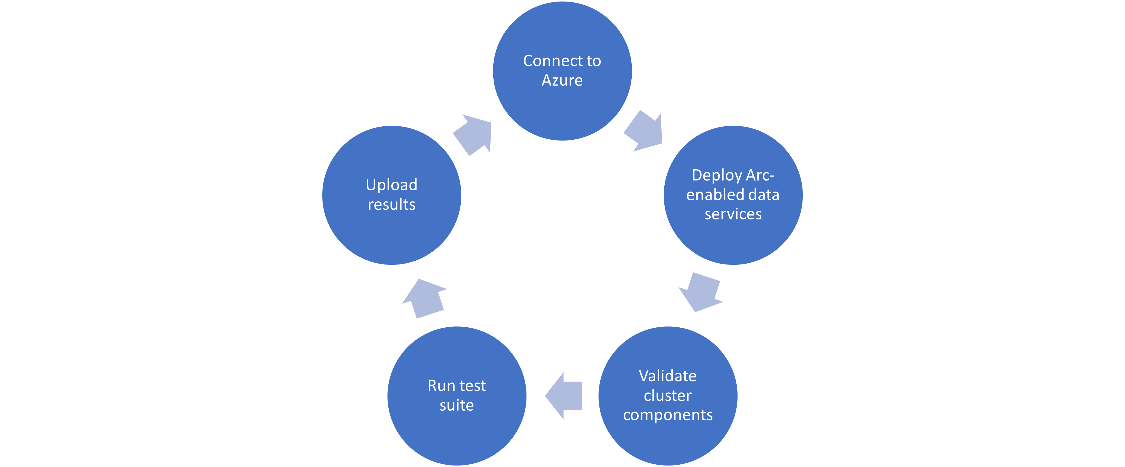
When Microsoft accepts the results, they add the new or updated solution to their list of validated solutions. At that point, the solution is officially supported. This process is repeated as needed as new component versions are introduced. Complete details about the validation testing and links to the GitHub repositories are available here.
More to come
Stay tuned for more additions and updates from Dell Technologies to the list of validated solutions for Azure Arc-enabled data services. Dell Technologies is leading the way on hybrid solutions, proven by our work with partners such as Microsoft on these validation efforts. Reach out to your Dell Technologies representative for more information about these solutions and validations.
Author: Doug Bernhardt
Sr. Principal Engineering Technologist

What’s New in PowerStoreOS 3.6?
Thu, 05 Oct 2023 14:22:36 -0000
|Read Time: 0 minutes
Dell PowerStoreOS 3.6 is the latest software release on the Dell PowerStore platform.
This release contains a diversified feature set in categories such as hardware, data protection, NVMe/TCP, file, and serviceability. The following list provides a brief overview of the major features in those categories:
- Hardware: PowerStoreOS 3.6 introduces the highly anticipated Data-In-Place (DIP) upgrade feature, which allows users to perform a hardware refresh while remaining online, with no downtime or host migration.
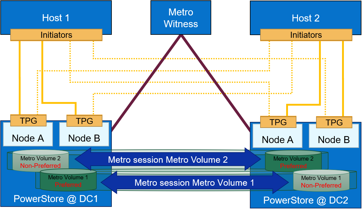
- Data Protection: PowerStoreOS 3.6 now includes support for Metro Witness Server, which allows users to configure a fully active-active configuration for metro volumes across two PowerStore clusters—with more intelligent failure handling, resiliency, and availability during an unplanned outage.
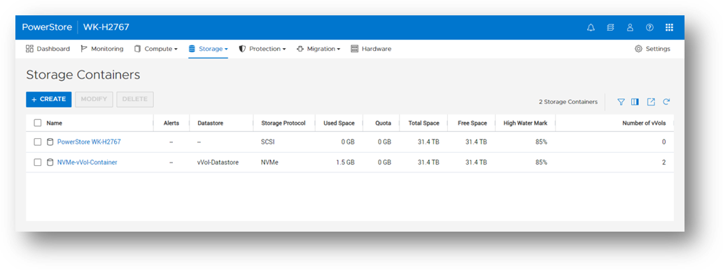
- NVMe/TCP enhancements: Users now have the option to use NVMe storage containers to support host access through the NVMe/TCP protocol for Virtual Volumes (vVols).
- File: Administrators can perform disaster recovery tests within a network bubble, while using an identical configuration as their production NAS server environment.
- Serviceability: To build on the existing remote syslog implementation, PowerStore alerts can now be forwarded to one or more remote syslog servers in PowerStoreOS 3.6. The following sections also provide information about the Non-Disruptive Upgrade (NDU) paths to the PowerStoreOS 3.6 release.
Hardware
Data-In-Place (DIP) upgrades
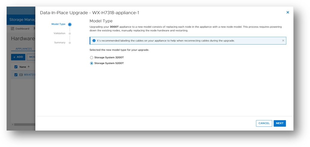
Data-In-Place upgrades allow users to convert their PowerStore Appliance from a PowerStore x000T model to a PowerStore x200T model. This is a non-disruptive process because only a single node is upgraded at a time, while the other node continues to service host I/O. Data-In-Place upgrades are performed easily through PowerStore Manager’s Hardware tab.
The following table outlines the supported Data-In-Place upgrade paths from the source to target models. For PowerStore 9000T models, only block-optimized upgrades are supported to the PowerStore 9200T model. When upgrading a PowerStore 3000T to a PowerStore 5200T model, additional NVRAM drives are required. When upgrading from a PowerStore 5000T model to a PowerStore 9200T model, a power supply upgrade may also be required.
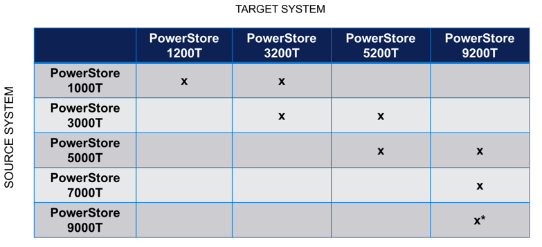
Note: *Denotes only block-optimized upgrade is supported
Data Protection
Metro Witness server support
Metro Volume support was introduced in PowerStoreOS 3.0. Since PowerStoreOS 3.0, Metro Volumes required manual intervention to fail over if the preferred site went down. PowerStoreOS 3.6 introduces the Metro Witness server feature. The Metro Witness server runs software that automatically forces the non-preferred site to remain online and service I/O if the preferred site were to go offline.
The Metro Witness software is a distributed RPM package available for Linux SLES or RHEL distributions. The RPM can be deployed on a bare-metal server or a virtual machine. The Metro Witness server and software can easily be set up in minutes!
NVMe/TCP enhancements
NVMe/TCP for Virtual Volumes (vVols)
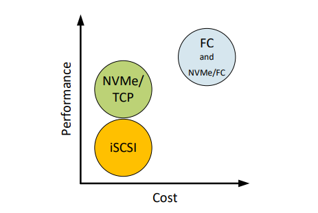
NVMe is transfer protocol that is specifically designed for connecting Solid State Drives (SSDs) to PCIe buses. NVMe over Fabrics (NVMe-oF) is an extension of the NVMe protocol to both TCP and Fibre Channel (FC) data streams. PowerStore currently supports both TCP and FC as NVMe-oF transports.
With the VMware vSphere 8.0U1 release, VMware introduced NVMe/TCP support for vVols. As the request for NVMe/TCP support grows, PowerStoreOS 3.6 expands its existing NVMe/TCP support to vVols as well! With this feature, PowerStore will be the industry’s 1st array to support NVMe/TCP for vVols[1].
From a performance perspective, NVMe/TCP is comparable to FC. From a cost perspective, NVMe/TCP infrastructure is cheaper than FC and can leverage existing network infrastructure. NVMe/TCP has a higher performance benefit than iSCSI and has lower hardware costs than FC. With the addition of NVMe/TCP support for vVols in PowerStoreOS 3.6, we combine performance, cost, and storage/compute granularity for system administrators.
File
Disaster Recovery (DR) tests within a network bubble
Many organizations are required to run disaster recovery (DR) tests using the exact same configuration as production. This includes identical IP addresses and fully qualified domain names. Running these types of tests reduces risk, increases reproducibility, and minimizes the chance of any surprises during an actual disaster recovery event.
These DR tests are carried out in an isolated environment, which is completely siloed from the production environment. Using network segmentation for proper isolation allows there to be no impact to production or replication. This allows users to meet the requirements of using identical IP addresses and FQDNs during their DR tests.
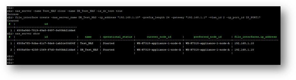
In PowerStoreOS 3.6, the appliance offers the file capability to create a Disaster Recovery Test (DRT) NAS server with a DR test interface. These DRT NAS servers permit a user to create a NAS server with an identical configuration as production, including the ability to duplicate IP addresses.
Note: DRT NAS servers and interfaces can only be configured using the CLI or REST API.
Serviceability
Remote Syslog support for PowerStore alerts
PowerStoreOS 2.0.x introduced support for remote syslog for auditing. These audit types included:
- Config
- System
- Service
- Authentication / Authorization / Logout
PowerStoreOS 3.6 has added support for forwarding of system alerts as well. This equips system administrators with more versatility to monitor their PowerStore appliances from a centralized location.
Upgrade Path
The following table outlines the NDU paths to upgrade to the PowerStoreOS 3.6 release. Depending on your source release, it may be a one or two step upgrade.
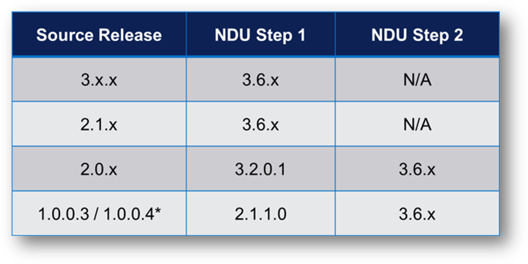
Note: *Denotes source release is not supported on PowerStore 500T models
Conclusion
The PowerStoreOS 3.6 release offers numerous feature enhancements that are unique and deepen the platform. It’s no surprise that PowerStore is deployed in over 90% of Fortune 500 vertical sectors[2] [1]. With PowerStore continuing to deliver on hardware, data protection, NVMe/TCP, file, and serviceability in this release, it’s no secret that the product is extremely adaptable and versatile in modern IT environments.
Resources
For additional information about the features described in this blog, plus other information about the PowerStoreOS 3.6 release, see the following white papers and solution documents:
- Dell PowerStore: Introduction to the Platform
- Dell PowerStore Manager Overview
- Dell PowerStore: File Capabilities
- Dell PowerStore: Replication Technologies
- Dell PowerStore: Virtualization Integration
- Dell PowerStore: Metro Volume
- Dell PowerStore: VMware vSphere Best Practices
- Dell PowerStore: VMware Site Recovery Manager Best Practices
- Dell PowerStore: VMware vSphere with Tanzu and TKG Clusters
- NVMe Transport Performance Comparison
Other Resources
- What’s New in PowerStoreOS 3.5?
- PowerStore Simple Support Matrix
- PowerStore: Info Hub – Product Documentation & Videos
- Dell Technologies PowerStore Info Hub
Author: Louie Sasa
[1] PowerStore is the industry's first array to support NVMe/TCP for vVols. Based on Dell internal analysis, September 2023.
[2] As of January 2023, based on internal analysis of vertical industry categories from 2022 Fortune 500 rankings.

Protecting VMware Workloads with PowerStore Metro Volumes
Mon, 09 Oct 2023 18:14:42 -0000
|Read Time: 0 minutes
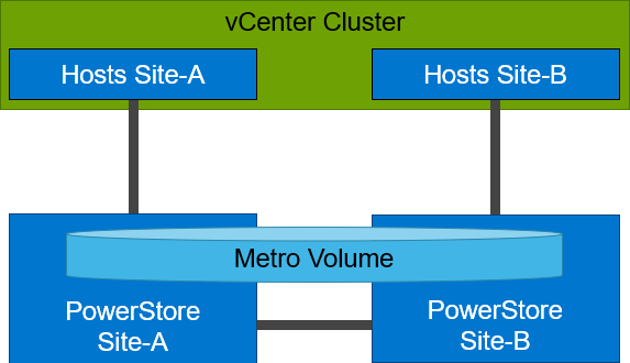
PowerStore’s metro volume replication allows storage administrators to create a high availability shared SAN environment across PowerStore clusters. Metro Volume provides symmetric active/active data access to VMware environments for use cases such as: planned migrations, disaster avoidance, and proactive resource rebalancing.
PowerStore supports two different configurations with Metro volume access: non-uniform and uniform. In this blog, our configuration is non-uniform.
Here is our sample non-uniform configuration, where hosts only have access to its local PowerStore system:
Creating the Metro Volume
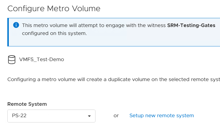
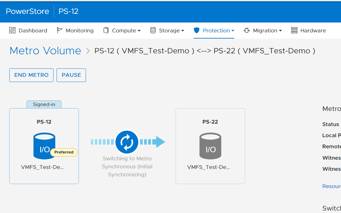
- Creating the metro volume session is a relatively simple process and involves a few clicks. Log into PowerStore Manager, select Storage, then select the volume (here, VMFS_Test-Demo), then select Configure Metro Volume.

2. On the Configure Metro Volume page, select the remote PowerStore to create the duplicate volume.
3. Now we see the volume switching to metro synchronous.
Creating the Metro Witness
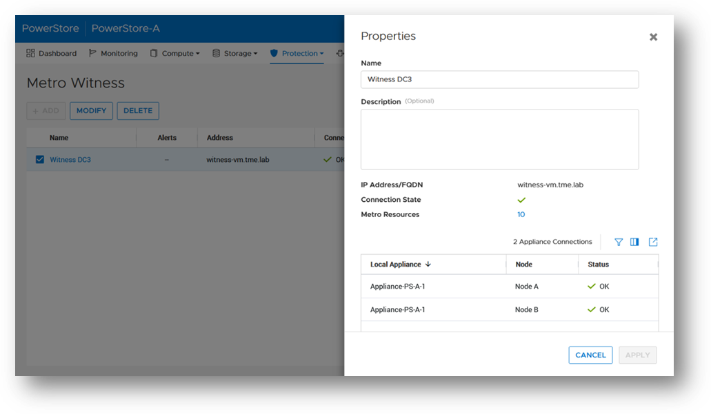
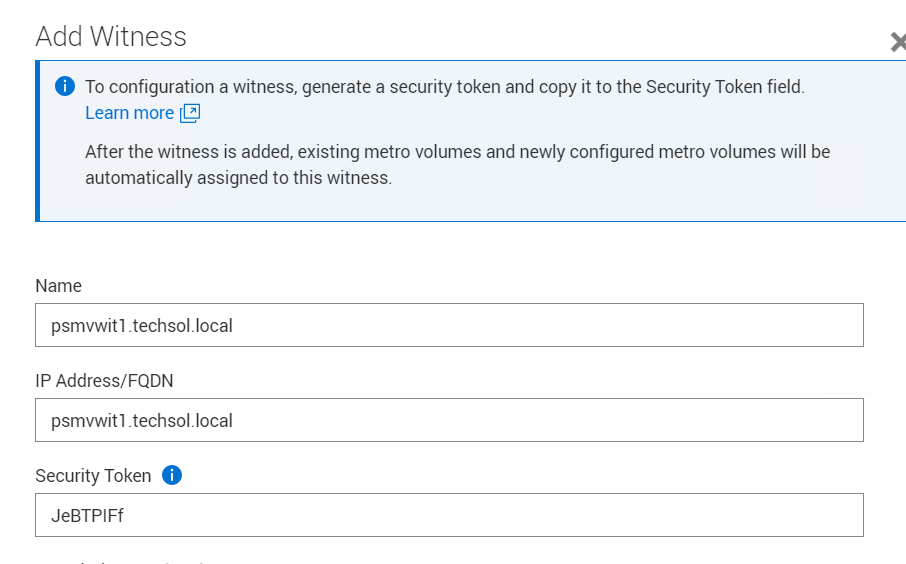
Starting with PowerStore version 3.6, Metro Volume supports a witness server. The witness server is a third party that is installed on a stand-alone host. The witness observes the status of the local and remote PowerStore systems. When a failure occurs, the witness server determines which system remains accessible to hosts and continues to service I/Os. When configuring Metro Witness on a PowerStore appliance, you must generate a unique token.
Note: You must configure the witness on each PowerStore cluster.
1. The following is an example of using the generate_token.sh script to create the token JeBTPIFf:

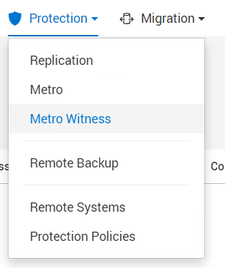
2. After gathering the token, select Protection > Metro Witness to enter the Metro witness configuration details.
3. Enter the witness details, including the DNS or IP address and security token.
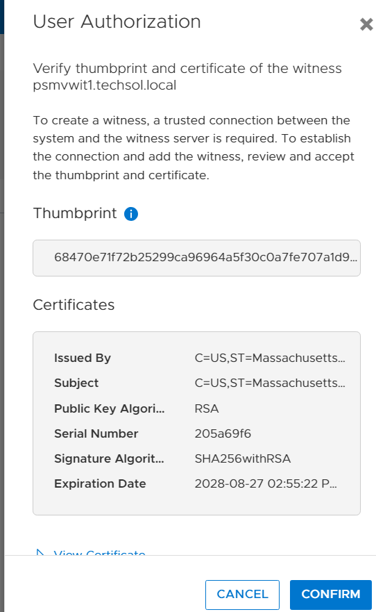
4. Confirm the witness settings.
5. Witness is connected to the metro sessions.
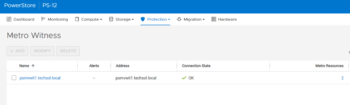
6. The metro session is synced, and the witness is now engaged.
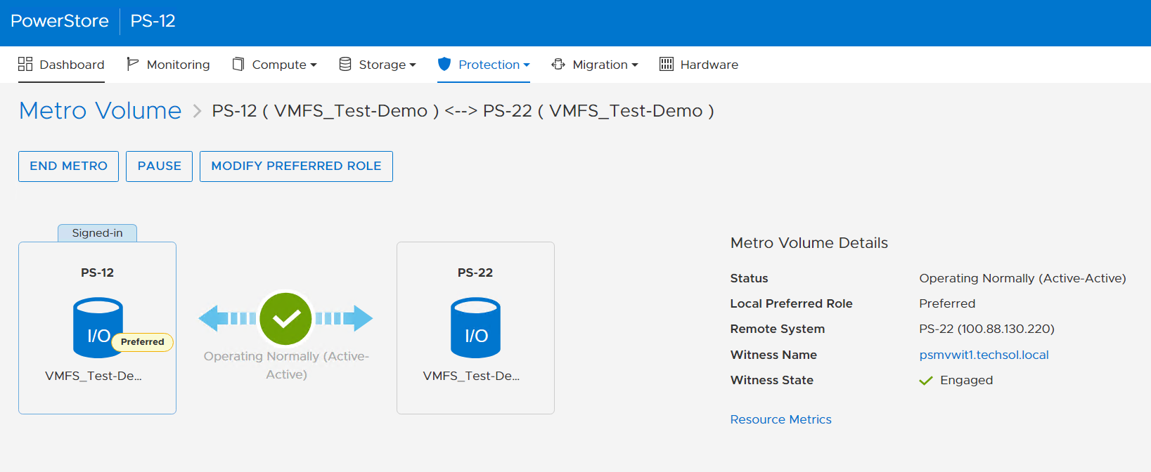
Metro Volume is designed to give VMware environments the ability to operate synchronously without disruption. Metro Volume integrates seamlessly with vSphere Metro Storage Cluster, for our PowerStore customers who must avoid disaster/data unavailability.
For more information, see the following resources.
Resources
- White paper: Dell PowerStore: Metro Volume
- White paper: Dell PowerStore: Replication Technologies
Author: Jason Gates

Dell PowerStore Enables Kubernetes Stretched Clusters

Thu, 05 Oct 2023 14:44:36 -0000
|Read Time: 0 minutes
Kubernetes (K8s) is one of the hottest platforms for building enterprise applications. Keeping enterprise applications online is a major focus for IT administrators. K8s includes many features to provide high availability (HA) for enterprise applications. Dell PowerStore and its Metro volume feature can make K8s availability even better!
Enhance local availability
K8s applications should be designed to be as ephemeral as possible. However, there are some workloads such as databases that can present a challenge. If these workloads are restarted, it can cause an interruption to applications, impacting service levels.
Deploying K8s on VMware vSphere adds a layer of virtualization that allows a virtual machine, in this case a K8s node, to be migrated live (vMotion) to another host in the cluster. This can keep pods up and running and avoid a restart when host hardware changes are required. However, if those pods have a large storage footprint and multiple storage appliances are involved, storage migrations can be resource and time consuming.
Dell PowerStore Metro Volume provides synchronous data replication between two volumes on two different PowerStore clusters. The volume is an identical, active-active copy on both PowerStore clusters. This allows compute-only virtual machine migrations. Compute-only migrations occur much faster and are much more practical in most cases. Therefore, more workloads can take advantage of vMotion and availability is increased.
PowerStoreOS 3.6 introduces a witness component to the Metro Volume architecture. The functional design of the witness adds more resiliency to Metro Volume deployments and further mitigates the risk of split-brain situations. The witness enables PowerStore OS 3.6 to make intelligent decisions across a wider variety of infrastructure outage scenarios, including unplanned outages.
K8s stretched or geo clusters
Spreading an application cluster across multiple sites is a common design for increasing availability. The compute part is easy to solve because K8s will restart workloads on the remaining nodes, regardless of location. However, if the workload requires persistent storage, the storage needs to exist in the other site.
PowerStore Metro Volume solves this requirement. Metro Volume support for VMware ESXi synchronizes volumes across PowerStore clusters to meet latency and distance requirements. In addition to the enhanced vMotion experience, PowerStore Metro volume provides active-active storage to VMware VMFS datastores that can span two PowerStore clusters. For in-depth information about PowerStore Metro Volume, see the white paper Dell PowerStore: Metro Volume.
Lab testing
We tested Dell PowerStore Metro Volume with a SQL Server workload driven by HammerDB on a stretched K8s cluster running on vSphere with three physical hosts and two PowerStore clusters[1]. The K8s cluster was running Rancher RKE2 1.25.12+rke2r1 with a VMFS datastore on PowerStore Metro volume using the VMware CSI provider for storage access. We performed vMotion compute only migrations and simulated storage network outages as part of the testing.
During the testing, the synchronized active-active copy of the volume was able to assume the IO workload, maintain IO access, and keep SQL Server and the HammerDB workload online. This prevented client disconnects and reconnects, application error messages, and costly recovery time to synchronize and recover data.
After we successfully completed testing on Rancher, we pivoted to another K8s platform: a VMware Tanzu Kubernetes Cluster deployed on VMware vSphere 8 Update 1. We deployed the SQL Server and HammerDB workload and performed a number of other K8s deployments in parallel. Workload test results were consistent. When we took the PowerStore cluster that was running the workload offline, both compute and storage remained available. The result was that the containerized applications were continuously available: not only during the failover, but during the failback as well.
In our Tanzu environment, Metro Volume went beyond data protection alone. It also provided infrastructure protection for objects throughout the Workload Management hierarchy. For example, the vSphere Tanzu supervisor cluster control plane nodes, pods, Tanzu Kubernetes clusters, image registry, and content library can all be assigned a VM storage policy and a corresponding storage class which is backed by PowerStore Metro Volumes. Likewise, NSX Manager and NSX Edge networking components on Metro Volume can also take advantage of this deployment model by remaining highly available during an unplanned outage.
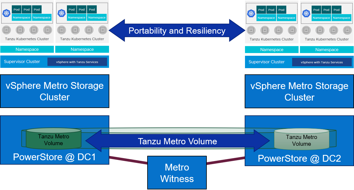
Figure 1. Metro Volume with a witness adds portability and resiliency to Tanzu deployments
For more information about PowerStore Metro Volume, increasing availability on SQL Server, and other new features and capabilities, be sure to check out all the latest information on the Dell PowerStore Info Hub page.
Authors:
Doug Bernhardt, Sr. Principal Engineering Technologist, LinkedIn
Jason Boche, Sr. Principal Engineering Technologist, LinkedIn
[1] Based on Dell internal testing, conducted in September 2023.

PowerStore: Lifecycle Management with Virtual Storage Integrator
Thu, 05 Oct 2023 14:39:06 -0000
|Read Time: 0 minutes
The integrated lifecycle management is available starting with virtual storage integrator (VSI) version 10.3. The plugin will upload the code, perform a health check, and update the PowerStore system. PowerStore code version 3.0 or later will be needed to take advantage of this capability.
This blog provides a quick overview of how to deploy Dell VSI and how to perform non-disruptive upgrades of PowerStore systems with the VSI plug-in in vCenter.
Components of VSI
VSI consists of two components—a virtual machine (VM) and a plug-in for vCenter that is deployed when VSI is registered for the vCenter. The VSI 10.3 open virtual appliance (OVA) template is available on the Dell Technologies support website and is supported with vSphere 6.7 U2 (and later) through 8.0.x for deployments with an embedded platform services controller (PSC).
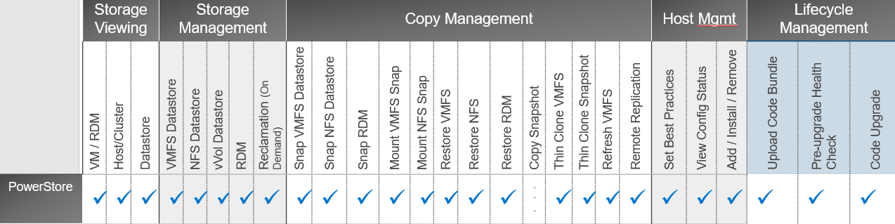
This chart shows VSI supported areas of operation for PowerStore:
Deployment
A deployed VSI VM needs 3.7 GB (thin) or 16 GB (thick) space on a datastore and is deployed with two vCPUs and 16 GB RAM. The VSI VM must be deployed on a network with access to the vCenter server and PowerStore. 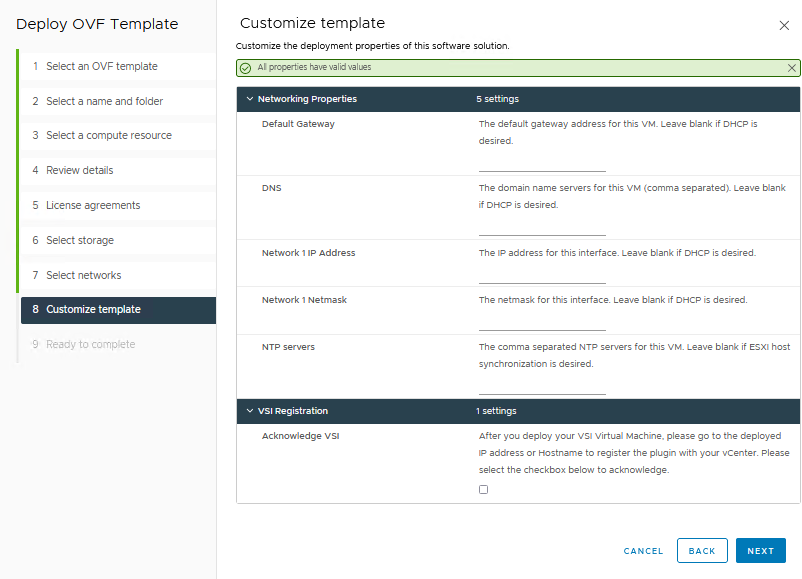
When the VM is deployed and started, you can access the plug-in management with https://<VSI-IP>.
Register VSI plug-in in vCenter
A wizard helps you register the plug-in in a vCenter. Initial setup only requires that you set the VSI password for the internal database and supply the vCenter address with username/password. Multiple vCenters can be registered if they are in a linked mode group.
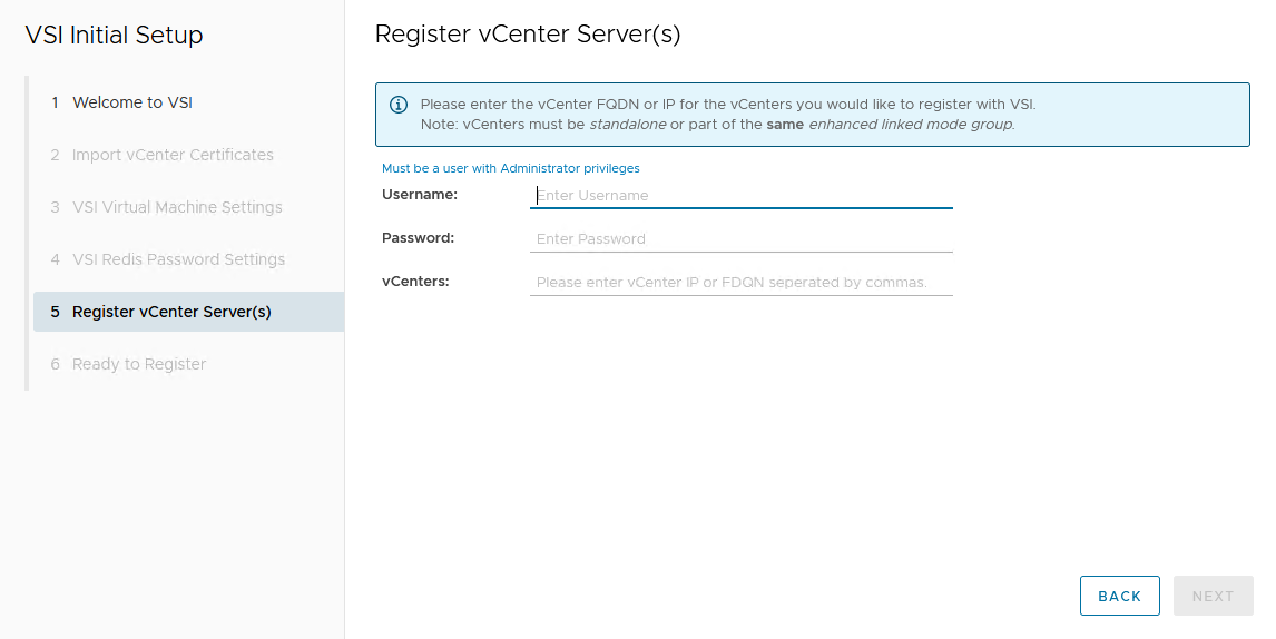
After the VSI VM is configured, it takes a few minutes for the VM to come online.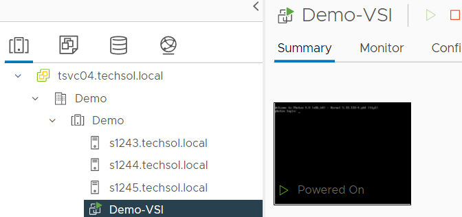
From the Dell VSI dashboard, select Storage Systems and the + sign to add the PowerStore system.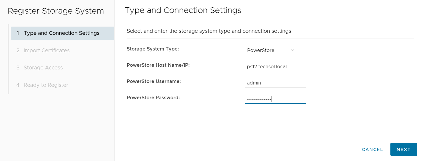
Perform a non-disruptive upgrade
VSI lifecycle management of PowerStore provides the following benefits:
- Upload the code bundle from the local device to PowerStore from the VSI plug-in to vCenter.
- Run a precheck after the bundle has been uploaded from the VSI plug-in to vCenter.
- Run the upgrade with the uploaded bundle from the VSI plug-in to vCenter.
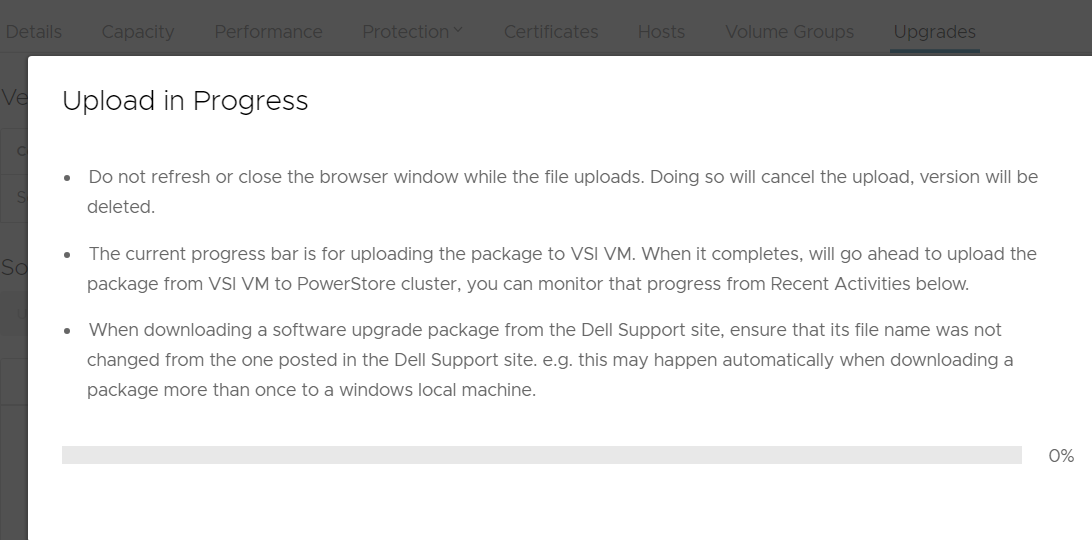
The non-disruptive upgrade process with the VSI plug-in requires three steps:
- Upload the code bundle.
- Complete a pre-upgrade health check.
- Perform a code upgrade.
To perform the non-disruptive upgrade, do the following:
- From the Dell VSI dashboard, select the PowerStore system.
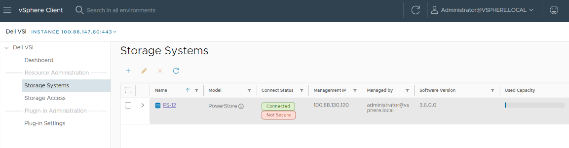 After selecting the PowerStore system, select the Upgrades tab.
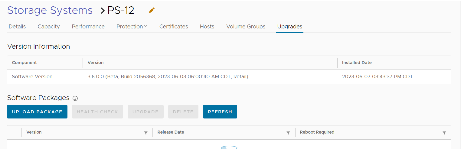
3. Under the Upgrades tab, select Upload package.
4. After uploading the code, select Run Health Check.
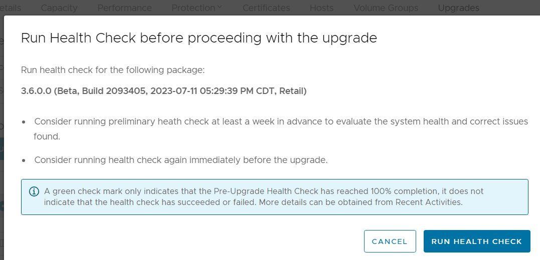
5. When the health check completes, kick off the upgrade process and monitor the status until complete.
Conclusion
Dell PowerStore extends the boundaries of mid-range storage with unmatched capabilities for enterprise storage. PowerStore integrates seamlessly with the VSI plugin. This system integration enables the orchestration necessary to deliver non-disruptive, streamlined PowerStore updates from within VMware vCenter.
Author: Jason Gates

Configuring PowerStore File Extension Filtering to Prevent Ransomware

Wed, 06 Sep 2023 18:12:28 -0000
|Read Time: 0 minutes
Overview
Disallowing known ransomware extensions from being written to the file system can be a simple and effective mechanism to deter and/or prevent ransomware. PowerStore file systems include a file extension filtering capability that restricts specific file extensions from being stored on an SMB share. Traditionally, this feature has been used to prevent users from storing non-business data on a share, however its uses extend to blocking malicious extensions from being written to a share at all.
File extension filtering can be leveraged in conjunction with other features such as CEPA to implement a ransomware strategy with multiple layers of defense. Let’s dive into how to configure PowerStore file extension filtering to better protect your system today.
Configuration
To configure file extension filtering:
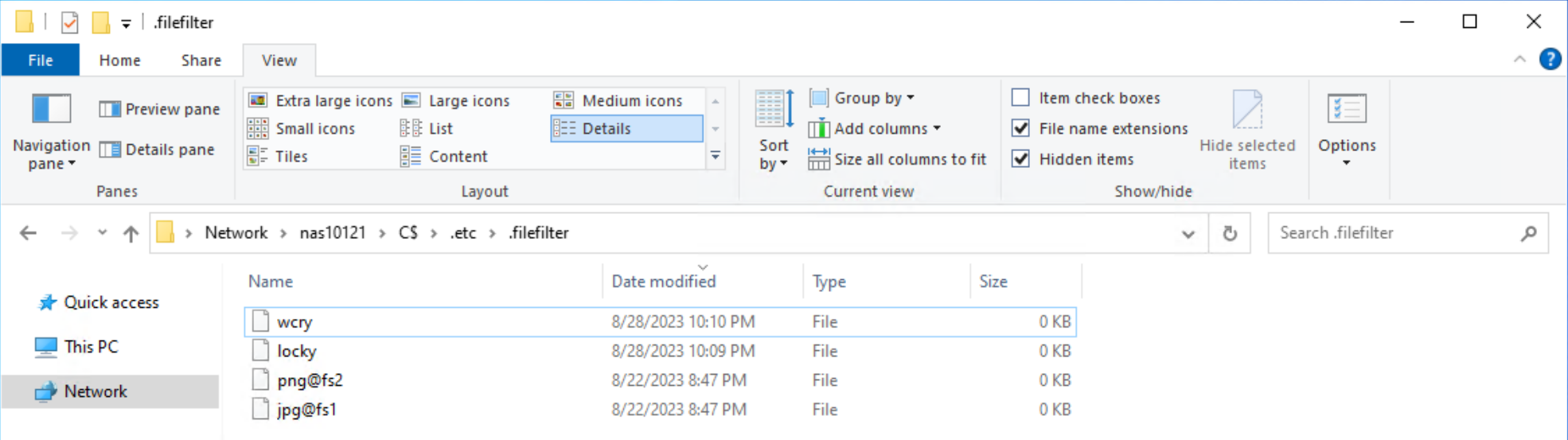
- Go to the \\<SMB_Server>\c$\.etc\.filefilter directory as an administrator
- To configure a filter, create an empty file using the naming convention extension@sharename
- For example, to filter .wcry ransomware files on the FS1 share, create a file named wcry@FS1
- To enable the filter on all shares on the SMB server, create the file with only the extension, such as wcry
You can configure multiple filters by creating additional files in this directory. For ransomware prevention use cases, create additional filters for other known ransomware extensions. Each SMB server has its own independent file extension filtering configuration, so each can be customized with its own configuration. The following figure shows an example of the configuration of the file extension filtering.
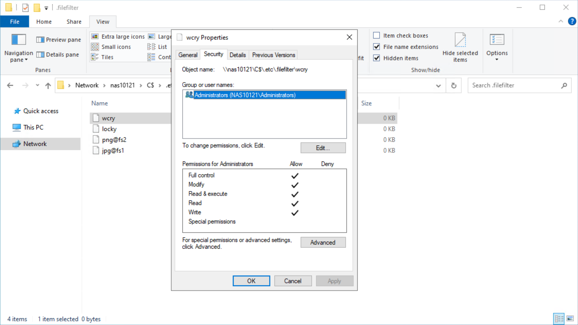
After configuring a file extension filter, you can permit exceptions for specific users or groups by changing the ACL on the filter file to provide Full Control privileges to the users or groups that should be excluded.
For example, if the Administrators group is provided Full Control permissions on the wcry filter file, then users in the Administrators group can store .wcry files on the share, while others cannot. Exceptions can be configured independently for each file filter being created, as shown in the following figure.
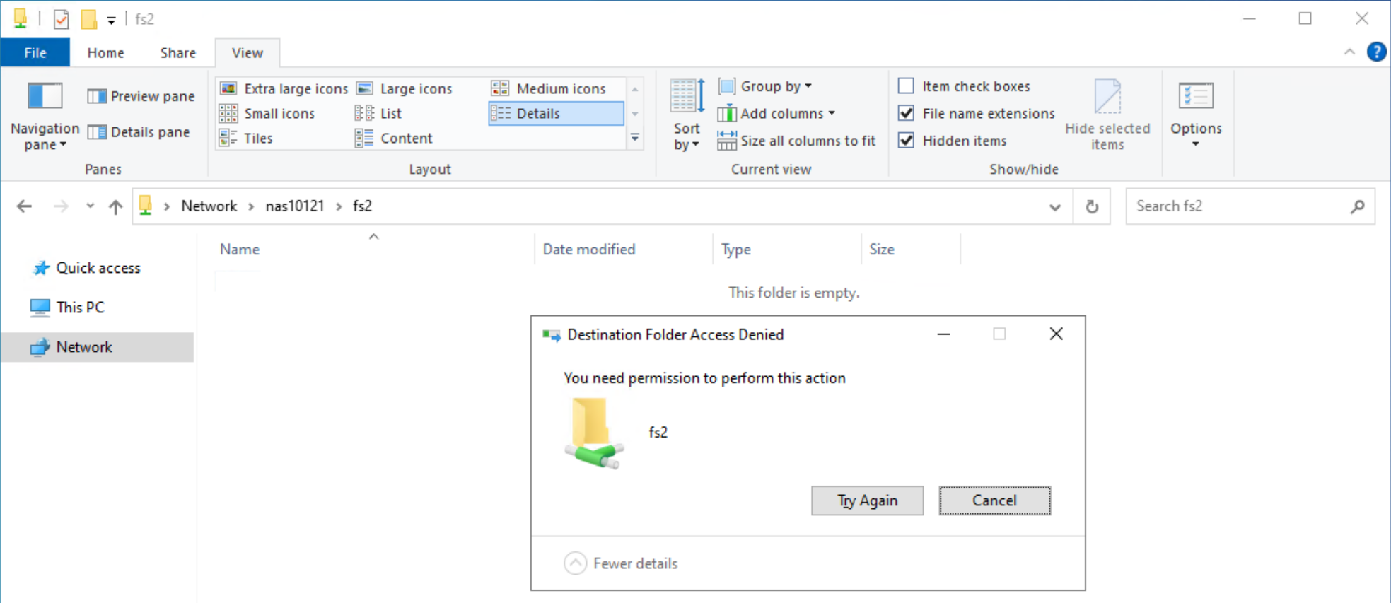
When users attempt to copy a file with a blocked extension, they receive an Access Denied error, as shown in the following figure.
Considerations
Note that this feature only works on SMB and does not filter file extensions when writing over NFS. Users could manually rename file extensions to bypass this filter, provided those other extensions are not also explicitly blocked, however malware may not be able to adapt and work around this as easily. Since the list of filtered extensions must be checked each time a file is written, having many filters could impact performance.
Conclusion
File extension filtering is a simple and powerful capability that provides administrators the ability to control the type of data that is stored on an SMB share. Easy to configure and able to provide an additional layer of protection against ransomware activity, file extension filtering is an effective addition to any comprehensive cybersecurity strategy to protect and secure your data.
Resources
The following resources provide more information about PowerStore:
Author: Wei Chen, Technical Staff, Engineering Technologist

PowerStore and SQL Server Ledger—Your Data Has Never Been More Secure!
Thu, 10 Aug 2023 17:49:01 -0000
|Read Time: 0 minutes
It’s all about security
Dell and Microsoft are constantly working together to provide the best security, availability, and performance for your valuable data assets. In the latest releases of PowerStoreOS 3.5 and SQL Server 2022, several new capabilities have been introduced that provide zero trust security for data protection.
PowerStore security
PowerStoreOS is packed with security features focused on secure platform, access controls, snapshot, auditing, and certifications. PowerStoreOS 3.5 introduces the following new features:
- STIG (Security Technical Implementation Guides) hardening, which enforces U.S. Department of Defense (DoD) specific rules regarding password complexity, timeout policies, and other practices.
- Multi-factor authentication to shield from hackers and mitigate poor password policies.
- Secure snapshots to prevent snapshots from being modified or deleted before the expiration date, even by an administrator.
- PowerProtect DD integration to create snapshots directly on Dell PowerProtect DD series appliances. The PowerStore Zero Trust video explains these features in more detail.
To enhance database security, Microsoft has introduced a new feature in SQL Server 2022, SQL Ledger. This feature leverages cryptography and blockchain architecture to produce a tamper-proof ledger of all changes made to a database over time. SQL Ledger provides cryptographic proof of data integrity to fulfill auditing requirements and streamline the audit process.
SQL Ledger 101
There are two main storage components to SQL Ledger. First is the database with special configuration that leverages blockchain architecture for increased security. The database resides on standard block or file storage. PowerStore supports both block and file storage, making it ideal for SQL Ledger deployments.
The second is an independently stored ledger digest that includes hash values for auditing and verification. The ledger digest is used as an append-only log to store point-in-time hash values for a ledger database. The ledger digest can then be used to verify the integrity of the main database by comparing a ledger block ID and hash value against the actual block ID and hash value in the database. If there is a mismatch, then some type of corruption or tampering has taken place.
This second component, the ledger digest, requires Write Once Read Many (WORM) storage. PowerStore File-Level Retention (FLR) features can be configured to provide WORM storage for SQL Ledger. Additionally, PowerStore FLR can also be configured to include a data integrity check to detect write-tampering that complies with SEC rule 17a-4(f).
Automatic storage and generation of database digests is only available for Microsoft Azure Storage. For on-premises deployments of SQL Server, Dell Technologies has your back! Let’s look at how this is done with PowerStore.
PowerStore configuration
It’s time to deep dive into how to configure this capability with Dell PowerStore and how to implement SQL Ledger. First, we need to configure the basis for WORM storage on PowerStore for the digest portion of SQL Ledger. This is done by creating a file system that is configured for FLR. Due to the write-once feature, this is typically a separate dedicated system. PowerStore supports multiple file systems on the same appliance, so dedicating a separate file system to WORM is not an issue.
WORM functionality is implemented by configuring PowerStore FLR. You have the option of FLR-Enterprise (FLR-E) or FLR-Compliance (FLR-C). FLR-C is the most restrictive.
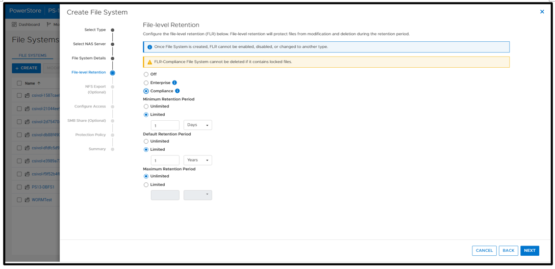
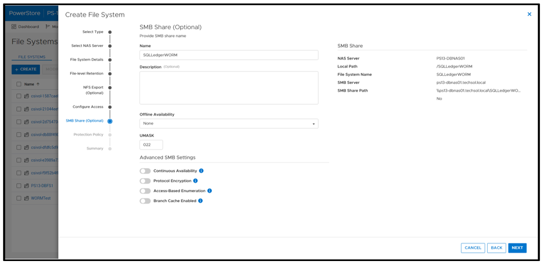
Next, configure an SMB (Server Message Block) Share for SQL Server to access the files. The settings here can be configured as needed; in this example, I am just using the defaults.
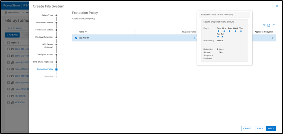
A best practice is to apply a protection policy. In this case, I am selecting a protection policy that has secure snapshot enabled. This will provide additional copies of the data that cannot be deleted prior to the retention period.
SQL Server database ops
Once the file system has been created, you can create a SQL Server database for ledger tables. Only ledger tables can exist in a ledger database. Therefore, it is common to create a separate database.
Database creation
The T-SQL CREATE DATABASE clause WITH LEDGER=ON indicates that it is a ledger database. Using a database name of SQLLedgerDemo, the most basic TSQL syntax would be:
CREATE DATABASE [SQLLedgerDemo] WITH LEDGER = ON
Ledger requires snapshot isolation to be enabled on the database with the following T-SQL command:
ALTER DATABASE SQLLedgerDemo SET ALLOW_SNAPSHOT_ISOLATION ON
Now that the database has been created, you can create either updatable or append-only ledger tables. These are database tables enhanced for SQL Ledger. Creating ledger tables is storage agnostic, so I am going to skip over it for brevity, but full instructions can be found in the Microsoft ledger documentation.
SQL Server ledger digest storage
The next step is to create the tamperproof database digest storage. This is where the verified block address and hash will be stored with a timestamp. The PowerStore file system that we just created will be used to fill this WORM storage device requirement. For it to operate correctly, we want to configure an append-only file. Because Windows does not have the ability to easily set this property, we can signal the PowerStore file system with FLR enabled that a file should be treated as append only.
First, create an empty file. This can be done in Windows File Explorer by right-clicking New and selecting Text Document. Next, right-click the file and select Properties. Select the Read-only attribute, click Apply, and then clear the Read-only attribute, click Apply, and then click OK.
Note: This action must be done on an empty file. It will not work once the file has been written to.
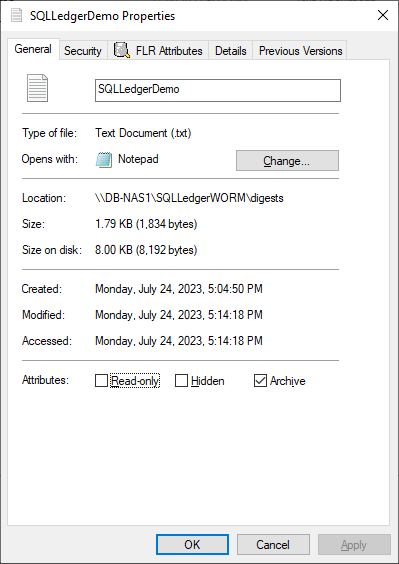
Notice that the dialog has an FLR Attributes tab. This is installed with the Dell FLR Toolkit and provides additional options not available in Windows, such as setting a file retention. Below we can also see that the FLR State of the file is set to Append-Only.
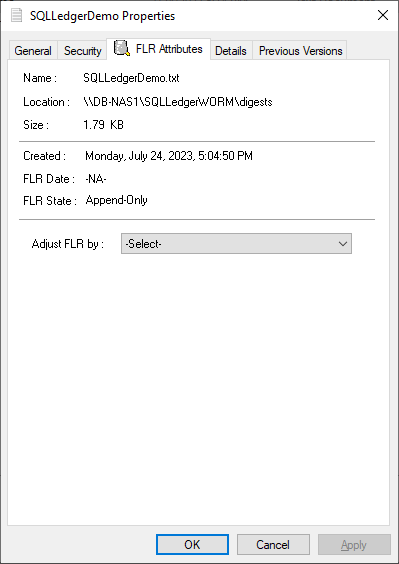
The FLR Toolkit can be downloaded from the Dell Support site. In addition to providing the ability to view the PowerStore FLR state, the FLR toolkit contains an FLR Explorer as well as additional command-line utilities.
The SQLLedgerDemo.txt file is now in the WORM state for SQL ledger digest storage: It is locked for delete and update, and can only be read or appended to.
For those of you running SQL Server on Linux, the process is the same to create the append only file. Create an empty file and then use the chmod command to remove and then reapply write permissions.
Before we get into populating the digest file, let’s understand what is being logged and how it is used. The digest file SQLLedgerDemo.txt will be populated by the output of a SQL Server stored procedure.
SQL Server ledger digest generation
Running the stored procedure sp_generate_database_ledger_digest on a ledger database produces the block ID and hash for our database verification. In this example, the output is:
{"database_name":"SQLLedgerDemo","block_id":0,"hash":"0xB222F775C84DC77BBA98B3C0E4E163484518102A10AE6D6DF216AFEDBD6D02E2","last_transaction_commit_time":"2023-07-24T13:52:20.3166667","digest_time":"2023-07-24T23:17:24.6960600"}This stored procedure is then run at regular intervals to produce a timestamped entry that can be used for validation.
SQL Server ledger digest verification
Using this info, another stored procedure, sp_verify_database_ledger, will recompute the hash for the given block ID to see if they match using the preceding output. You validate the block by passing in a previously generated digest to the stored procedure:
sp_verify_database_ledger N'{"database_name":"SQLLedgerDemo","block_id":0,"hash":"0xB222F775C84DC77BBA98B3C0E4E163484518102A10AE6D6DF216AFEDBD6D02E2","last_transaction_commit_time":"2023-07-24T13:52:20.3166667","digest_time":"2023-07-24T23:17:24.6960600"}'If it returns 0, there is a match; otherwise, you receive the following errors. You can verify this by modifying the hash value and calling sp_verify_database_ledger again, which will produce these errors.
Msg 37368, Level 16, State 1, Procedure sp_verify_database_ledger, Line 1   [Batch Start Line 10]
The hash of block 0 in the database ledger does not match the hash provided in the digest for this block.
Msg 37392, Level 16, State 1, Procedure sp_verify_database_ledger, Line 1   [Batch Start Line 10]
Ledger verification failed.
Automating ledger digest generation and validation
Using these stored procedures, you put an automated process in place to generate a new ledger digest, append it to the file created above, and then verify that there is a match. If there is not a match, then you can go back to the last entry in the digest to determine when the corruption or tampering took place. If you're following the SQL Server Best Practices for PowerStore, you're taking regular snapshots of your database to enable fast point-in-time recovery. Because Dell PowerStore snapshots are secure and immutable, they serve as a fast recovery point, adding an additional layer of protection to critical data.
Because the generation and validation is driven with SQL Server stored procedures, automating the process using your favorite tools is extremely easy. Pieter Vanhove at Microsoft wrote a blog post, Ledger - Automatic digest upload for SQL Server without Azure connectivity, about how to automate the digest generation and verification using SQL Agent. The blog post contains sample scripts to create SQL Server Agent jobs to automate the entire process!
Summary
Your data can never be too secure. PowerStore secure snapshot capabilities add an additional another layer of security to any database. PowerStore FLR capabilities and SQL Server Ledger can be combined to further secure your database data and achieve compliance with the most stringent security requirements. Should the need arise, PowerStore secure, immutable snapshots can be used as a fast recovery point.
Author:
Doug Bernhardt
Sr. Principal Engineering Technologist
https://www.linkedin.com/in/doug-bernhardt-data/

Getting Tough with PowerStore and STIG Mode: Meeting Federal Compliance Requirements
Wed, 09 Aug 2023 15:22:52 -0000
|Read Time: 0 minutes
US Federal Security Technical Information Guide (STIG) overview
Compliance with the US Federal Security Technical Information Guide requirements, (STIG compliance) is a critical feature for many of our customers in the Federal space. STIG compliance is also a prerequisite for the Approved Product List (APL) certification. The latter is also a requirement for some Department of Defense (DoD) sites.
How PowerStoreOS 3.5 is supporting STIG
The new PowerStoreOS 3.5 release now supports STIG mode. This mode applies configuration changes to the core of the product for the system to meet STIG requirements related to the operating system, embedded web server, internal databases, and various networking functions.
Enabling STIG mode
When a user wants to enable STIG mode, they need to run a REST API command against the PowerStore cluster or use the PowerStore command line interface (PowerStore CLI). The following is an example of the REST API command where <IP> is the IP of the PowerStore cluster.
curl -kv https://<IP>:443/api/rest/security_config/1?is_async=true --user admin:Password -X PATCH --data '{"is_stig_enabled":true}' -H "Content-Type:application/json“You can also enable STIG mode by issuing the following command in the PowerStore CLI:
pstcli -user admin -password Password -destination <IP> security_config -id 1 set -is_stig_enabled true -async
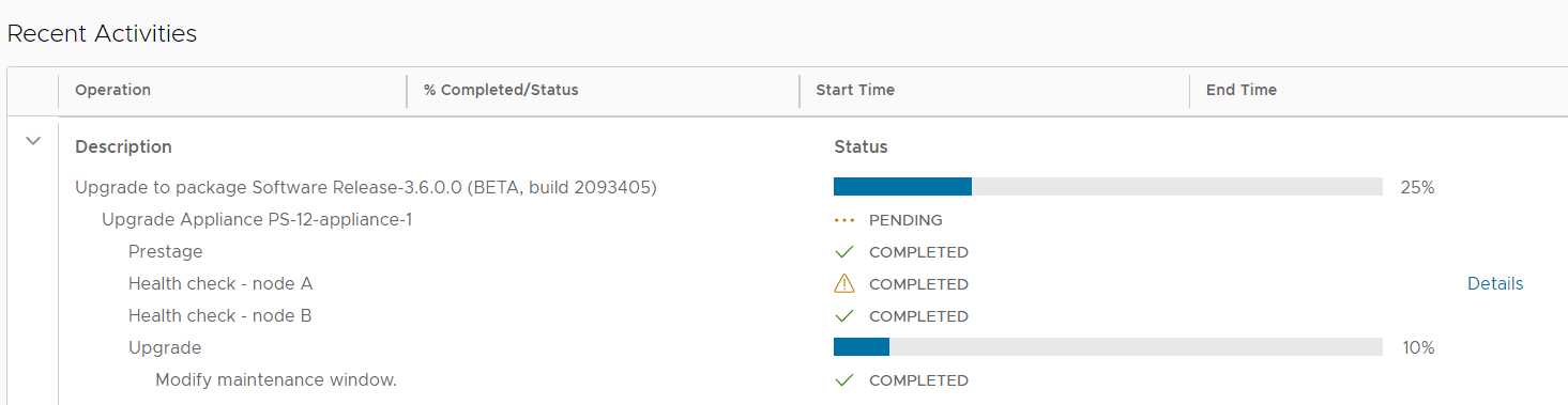
When the STIG enable process is kicked off, it takes about 45 minutes to enable STIG mode for a single appliance system. Larger clusters will take a little longer. You can confirm whether the process is running or completed by viewing the job status under Monitoring > Jobs in PowerStore Manager (Figure 1). In this example, notice that the ‘Modify security configuration’ job status is Completed.

Figure 1. STIG enablement job status
Enabling STIG is comparable to a PowerStoreOS upgrade, where the process is coordinated across the cluster, its nodes, and appliances. The process requires reboots across the nodes because of kernel changes and because additional Federal Information Processing Standard (FIPS) settings are enabled. FIPS in this case restricts the communication paths and the encryption used in those paths to be FIPS 140-2 compliant. By default, the drives in PowerStore are already leveraging FIPS encryption for storing data. STIG mode only enables the FIPS communication path part of the FIPS compliance, at the kernel level. This includes items such as data in flight and replication peers.
Disabling STIG mode, after it is enabled, is not supported. This is because a user enabling STIG mode is protecting top secret data, and we don’t want to enable anyone to disable this mode. The only way to remove or disable STIG mode from the PowerStore would be to perform a factory reset, which would delete all data. When STIG mode is enabled, PowerStore Manager displays a new login banner, as shown in Figure 2.
Figure 2. New STIG login banner
The user needs to scroll through this banner and click I agree to be able to input their credentials. They are then prompted to create a new password that meets STIG requirements and increases the security posture of the system. These requirements are outlined in the blue section of Figure 3.
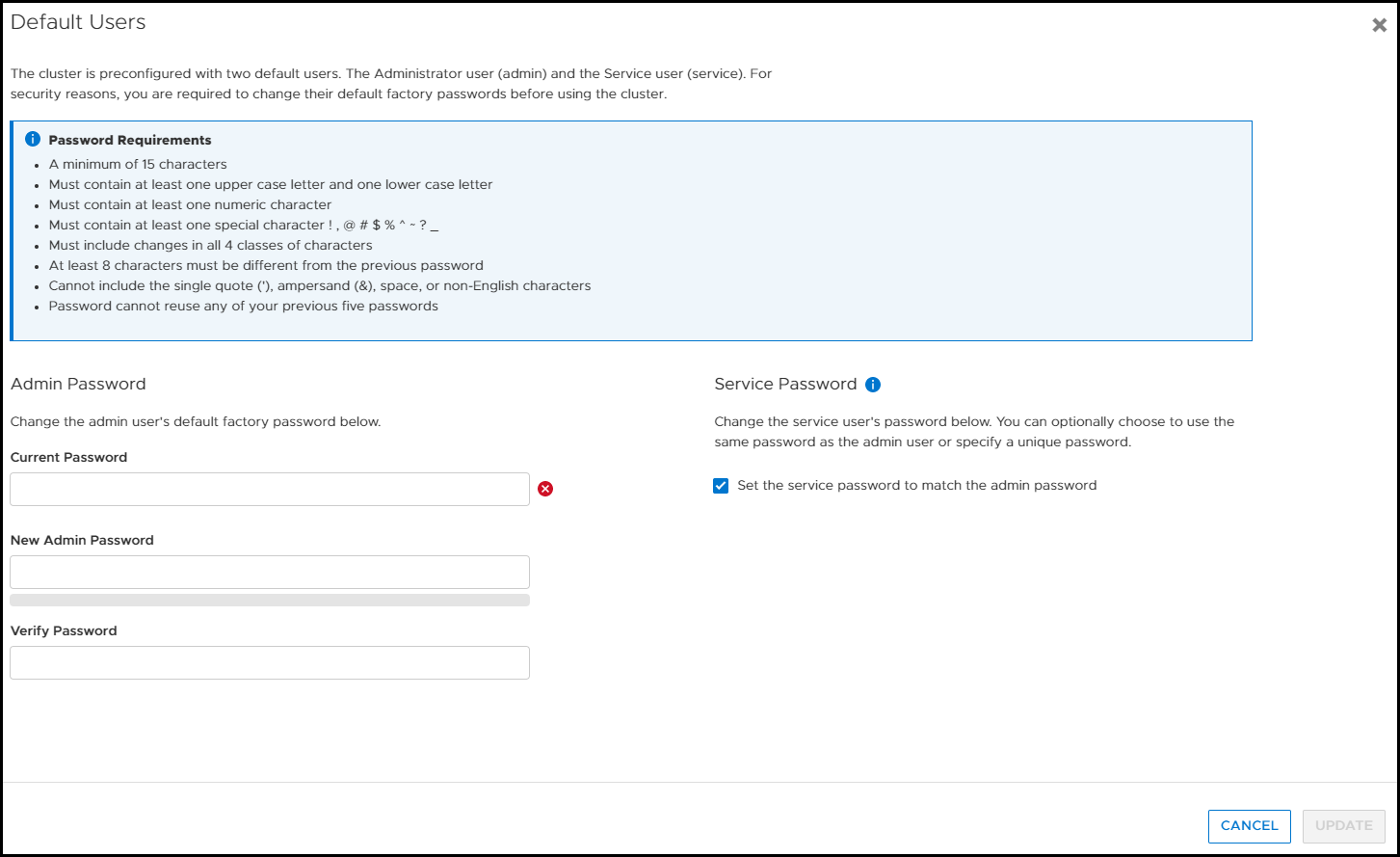
Figure 3. Update password to meet STIG requirements
Now, after logging in for the first time, you can notice a few of the changes from having enabled STIG mode in PowerStore Manager. If we look at the Login Message under Settings, the user can’t disable or change the login banner message. In Figure 4, notice that Enabled is grayed out and the login message is read-only. (If this system weren’t in STIG mode, users would be able to set their own login banner message, and enable or disable it as they see fit.)
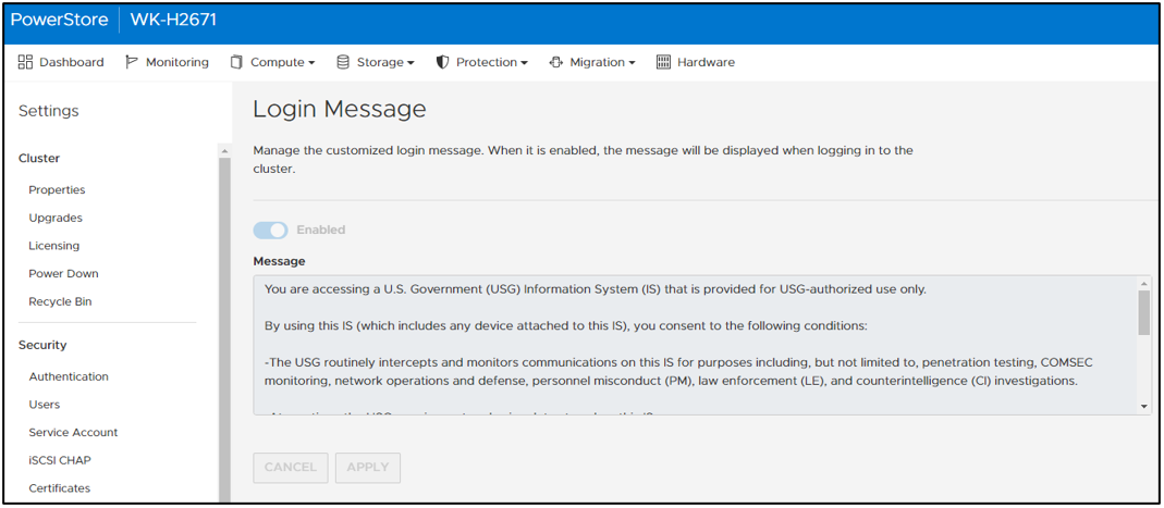
Figure 4. Login message can’t be changed or disabled
In PowerStore Manager, under Settings > Security > Session Timeout, only users with the Administrator or Security Administrator role can change the session timeout value. The options are 5, 10, and 20 minutes. Ten minutes is the default for STIG mode (Figure 5).
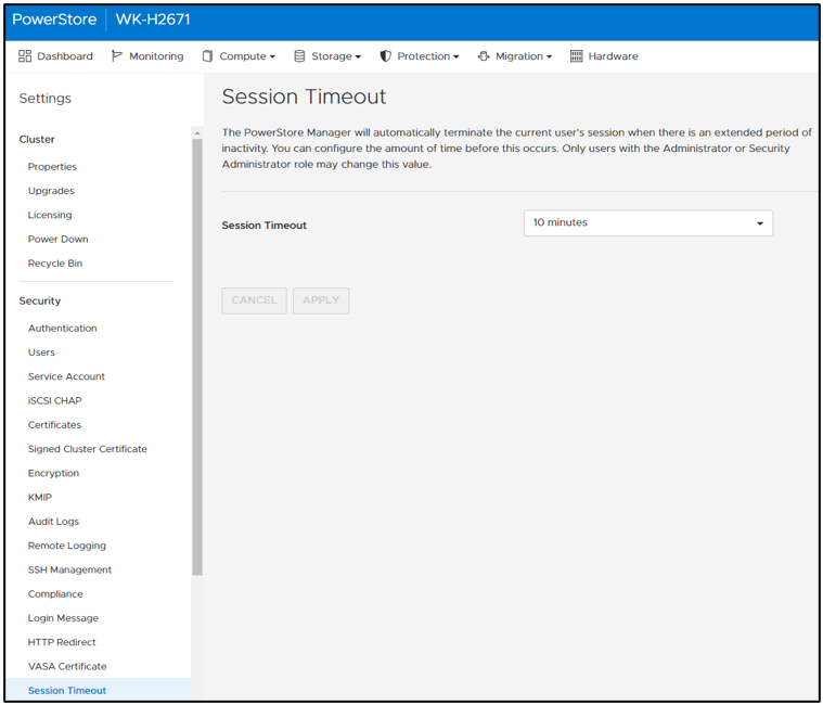
Figure 5. Default STIG mode session timeout
STIG mode also disables the ability for users to add PowerStore appliances to a STIG enabled cluster. Users who want to use multiple appliances must join them together before enabling STIG mode. This helps ensure a high security posture. On the Hardware page, notice that the ADD button is grayed out and that mousing over it displays a tooltip message (Figure 6).
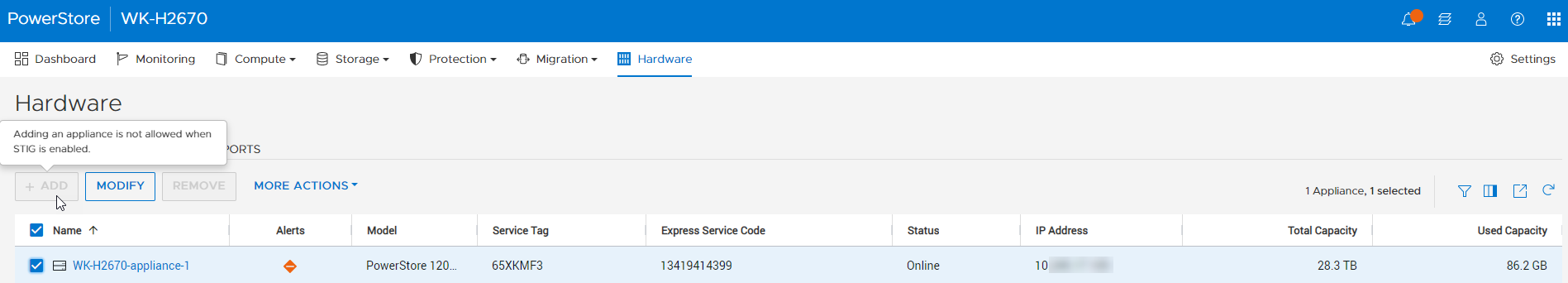
Figure 6. Add appliance disabled
After STIG mode is enabled, the Advanced Intrusion Detection Environment (AIDE) is also enabled on PowerStore. AIDE runs a scan once a day to look for file tampering of system files. This is another method that STIG uses to protect the PowerStore. Because PowerStore system files should only be changed during upgrades, it is easy for AIDE to detect tampering. If tampering is detected, PowerStore alerts appear, and the audit log is updated.
Conclusion
This blog provided you a quick glimpse into how easy it is to enable STIG mode on PowerStore to increase the system’s security posture and meet Federal compliance requirements. We went over some of the basic changes that STIG mode makes on the surface. Many more security items are changed underneath the covers of PowerStore to make it secure for Federal environments. Federal users will benefit from these security features and still be able to take advantage of PowerStore’s intuitive interface.
Resources
For more information about PowerStoreOS 3.5, and PowerStore in general, check out these resources:
- Dell Technologies PowerStore Info Hub
- Dell PowerStore: Cybersecurity White Paper
- Dell PowerStore: Blogs
Author: Andrew Sirpis

Dell PowerStore: vVol Replication with PowerCLI

Wed, 14 Jun 2023 14:57:44 -0000
|Read Time: 0 minutes
Overview
In PowerStoreOS 2.0, we introduced asynchronous replication of vVol-based VMs. In addition to using VMware SRM to manage and control the replication of vVol-based VMs, you can also use VMware PowerCLI to replicate vVols. This blog shows you how.
To protect vVol-based VMs, the replication leverages vSphere storage policies for datastores. Placing VMs in a vVol storage container with a vSphere storage policy creates a replication group. The solution uses VASA 3.0 storage provider configurations in vSphere to control the replication of all individual configuration-, swap-, and data vVols in a vSphere replication group on PowerStore. All vVols in a vSphere replication group are managed in a single PowerStore replication session.
Requirements for PowerStore asynchronous vVol replication with PowerCLI:
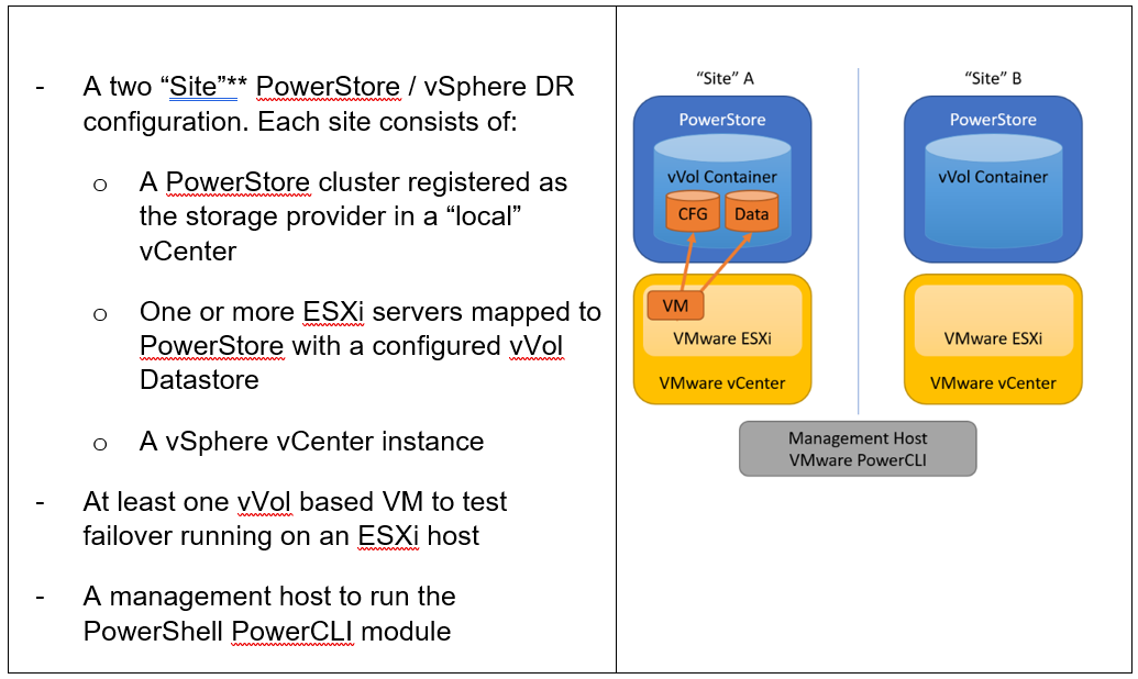
**As in VMware SRM, I’m using the term “site” to differentiate between primary and DR installation. However,
depending on the use case, all systems could also be located at a single location.
Let’s start with some terminology used in this blog.
PowerStore cluster | A configured PowerStore system that consists of one to four PowerStore appliances. |
PowerStore appliance | A single PowerStore entity that comes with two nodes (node A and node B). |
PowerStore Remote Systems (pair) | Definition of a relationship of two PowerStore clusters, used for replication. |
PowerStore Replication Rule | A replication configuration used in policies to run asynchronous replication. The rule provides information about the remote systems pair and the targeted recovery point objective time (RPO). |
PowerStore Replication Session | One or more storage objects configured with a protection policy that include a replication rule. The replication session controls and manages the replication based on the replication rule configuration. |
VMware vSphere VM Storage Policy | A policy to configure the required characteristics for a VM storage object in vSphere. For vVol replication with PowerStore, the storage policy leverages the PowerStore replication rule to set up and manage the PowerStore replication session. A vVol-based VM consists of a config vVol, swap vVol, and one or more data vVols. |
VMware vSphere Replication Group | In vSphere, the replication is controlled in a replication group. For vVol replication, a replication group includes one or more vVols. The granularity for failover operations in vSphere is replication group. A replication group uses a single PowerStore replication session for all vVols in that replication group. |
VMware Site Recovery Manager (SRM) | A tool that automates failover from a production site to a DR site. |
Preparing for replication
For preparation, similar to VMware SRM, there are some steps required for replicated vVol-based VMs:
Note: When frequently switching between vSphere and PowerStore, an item may not be available as expected. In this case, a manual synchronization of the storage provider in vCenter might be required to make the item immediately available. Otherwise, you must wait for the next automatic synchronization.
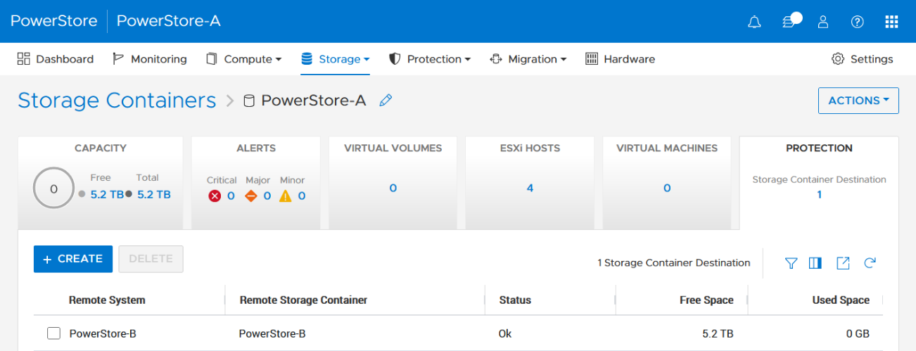
- Using the PowerStore UI, set up a remote system relationship between participating PowerStore clusters. It’s only necessary to perform this configuration on one PowerStore system. When a remote system relationship is established, it can be used by both PowerStore systems.
Select Protection > Remote Systems > Add remote system.
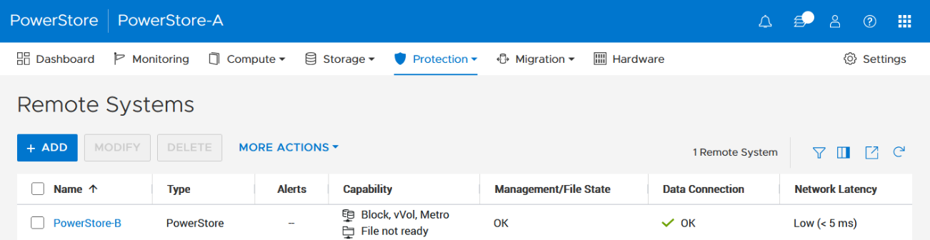
When there is only a single storage container on each PowerStore in a remote system relationship, PowerStoreOS also creates the container protection pairing required for vVol replication.
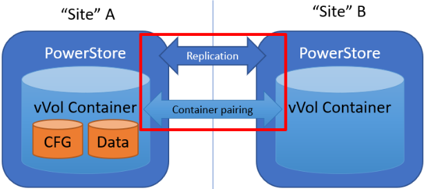
To check the configuration or create storage container protection pairing when more storage containers are configured, select Storage > Storage Containers > [Storage Container Name] > Protection.
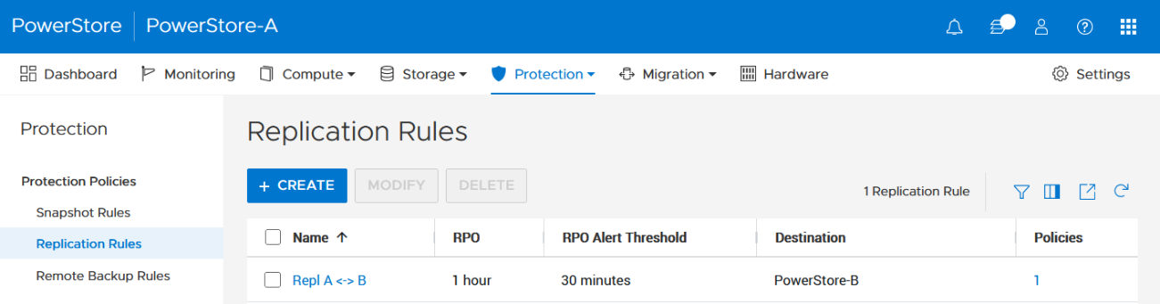
2. The VMware Storage Policy (which is created in a later step) requires existing replication rules on both PowerStoresystems, ideally with same characteristics. For this example, the replication rule replicates from PowerStore-A to PowerStore-B with a RPO of one hour, and 30 minutes for the RPO Alert Threshold.
Select Protection > Protection Policies > Replication Rules.
3. As mentioned in the Overview, VASA 3.0 is used for the communication between PowerStore and vSphere. If not configured already, register the local PowerStore in both vCenters as the storage provider in the corresponding vSphere vCenter instance.
In the vSphere Client, select [vCenter server] > Configuration > Storage Providers.
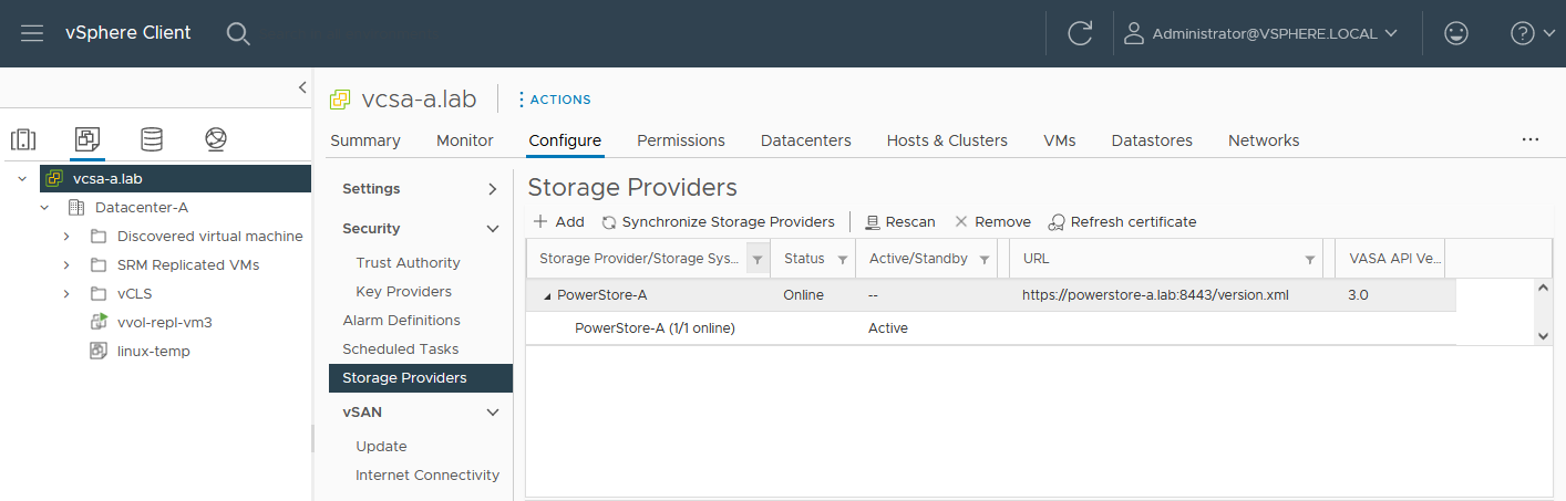
Use https://<PowerStore>:8443/version.xml as the URL with the PowerStore user and password to register the PowerStore cluster.
Alternatively, use PowerStore for a bidirectional registration. When vCenter is registered in PowerStore, PowerStoreOS gets more insight about running VMs for that vCenter. However, in the current release, PowerStoreOS can only handle a single vCenter connection for VM lookups. When PowerStore is used by more than one vCenter, it’s still possible to register a PowerStore in a second vCenter as the storage provider, as mentioned before.
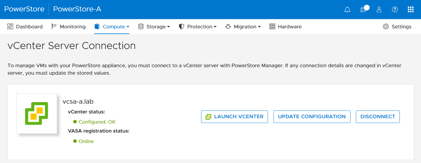
In the PowerStore UI, select Compute > vCenter Server Connection.
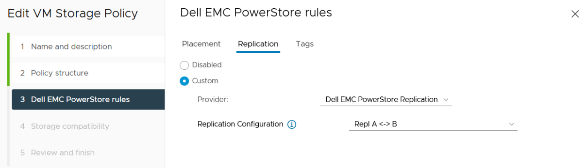
4. Set up a VMware storage policy with a PowerStore replication rule on both vCenters.
The example script in the section section Using PowerCLI and on myScripts4u@github requires the same Storage Policy name for both vCenters.
In the vSphere Client, select Policies and Profiles > VM Storage Policies > Create.
Enable “Dell EMC PowerStore” storage for datastore specific rules:
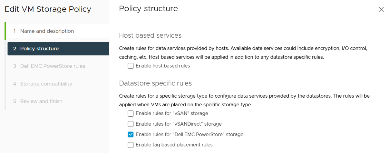
then choose the PowerStore replication rule:
5. Create a VM on a vVol storage container and assign the storage protection policy with replication.
When a storage policy with replication is set up for a VM, you must specify a replication group. Selecting “automatic” creates a replication group with the name of the VM. Multiple VMs can be protected in one replication group.
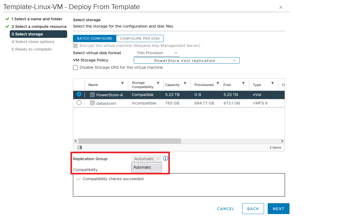
When deploying another VM on the same vVol datastore, the name of the other replicated VM appears in the list for the Replication Group.
All vVol replication operations are on a Replication Group granularity. For instance, it’s not possible to failover only a single VM of a replication group.
That’s it for the preparation! Let’s continue with PowerCLI.
Using PowerCLI
Disclaimer: The PowerShell snippets shown below are developed only for educational purposes and provided only as examples. Dell Technologies and the blog author do not guarantee that this code works in your environment or can provide support in running the snippets.
To get the required PowerStore modules for PowerCLI, start PowerShell or PowerShell ISE and use Install-Module to install VMware.PowerCLI:
PS C:\> Install-Module -Name VMware.PowerCLI
The following example uses the replication group “vvol-repl-vm1”, which includes the virtual machines “vvol-repl-vm1” and “vvol-repl-vm2”. Because a replication group name might not be consistent with a VM to failover, the script uses the virtual machine name “vvol-repl-vm2” to get the replication group for failover.
Failover
This section shows an example failover of a vVol-based VM “vvol-vm2” from a source vCenter to a target vCenter.
1. Load modules, allow PowerStore to connect to multiple vCenter instances, and set variables for the VM, vCenters, and vCenter credentials. The last two commands in this step establishes the connection to both vCenters.
Import-Module VMware.VimAutomation.Core
Import-Module VMware.VimAutomation.Common
Import-Module VMware.VimAutomation.Storage
Set-PowerCLIConfiguration -DefaultVIServerMode 'Multiple' -Scope ([VMware.VimAutomation.ViCore.Types.V1.ConfigurationScope]::Session) -Confirm:$false  | Out-Null
$virtualmachine = "vvol-vm2"                   # Enter VM name of a vVol VM which should failover
$vcUser = 'administrator@vsphere.local'        # Change this to your VC username
$vcPass = 'xxxxxxxxxx'                         # VC password
$siteA = "vcsa-a.lab"                          # first vCenter
$siteB = "vcsa-b.lab"                          # second vCenter
Connect-VIServer -User "$vcUser" -Password "$vcPass" -Server $siteA -WarningAction SilentlyContinue
Connect-VIServer -User "$vcUser" -Password "$vcPass" -Server $siteB -WarningAction SilentlyContinue
2. Get replication group ($rg), replication group pair ($rgPair), and storage policy ($stoPol) for the VM. Because a replication group may have additional VMs, all VMs in the replication group are stored in $rgVMs.
$vm = get-vm $virtualmachine
# find source vCenter – this allows the script to failover (Site-A -> Site-B) and failback (Site-B -> Site-A)
$srcvCenter=$vm.Uid.Split(":")[0].Split("@")[1]
if ( $srcvCenter -like $siteA ) {
     $siteSRC=$siteA
     $siteDST=$siteB
} else {
     $siteSRC=$siteB
    $siteDST=$siteA
}
$rg = get-spbmreplicationgroup -server $siteSRC -VM $vm
$rgPair = Get-SpbmReplicationPair -Source $rg
$rgVMs=(Get-SpbmReplicationGroup -server $siteSRC -Name $rg| get-vm)
$stoPol = ( $vm | Get-SpbmEntityConfiguration).StoragePolicy.Name
3. Try a graceful shutdown of VMs in $rgVMs and wait ten seconds. Shut down VMs after three attempts.
$rgVMs | ForEach-Object {
     if ( (get-vm $_).PowerState -eq "PoweredOn")
     {
         stop-vmguest -VM $_ -confirm:$false -ErrorAction silentlycontinue | Out-Null
         start-sleep -Seconds 10
         $cnt=1
         while ((get-vm $_).PowerState -eq "PoweredOn" -AND $cnt -le 3 ) {
            Start-Sleep -Seconds 10
            $cnt++
         }
         if ((get-vm $_).PowerState -eq "PoweredOn") {
            stop-vm $_ -Confirm:$false  | Out-Null
         }
     }
}
4. It’s now possible to prepare and execute the failover. At the end, $vmxfile contains the vmx files that are required to register the VMs at the destination. During failover, a final synchronize before doing the failover ensures that all changes are replicated to the destination PowerStore. When the failover is completed, the vVols at the failover destination are available for further steps.
$syncRg = Sync-SpbmReplicationGroup -PointInTimeReplicaName "prePrepSync" -ReplicationGroup $rgpair.target
$prepareFailover = start-spbmreplicationpreparefailover $rgPair.Source -Confirm:$false -RunAsync
Wait-Task $prepareFailover
$startFailover = Start-SpbmReplicationFailover $rgPair.Target -Confirm:$false -RunAsync
$vmxfile = Wait-Task $startFailover
5. For clean up on the failover source vCenter, we remove the failed over VM registrations. On the failover target, we search for a host ($vmhostDST) and register, start, and set the vSphere Policy on VMs. The array @newDstVMs will contain VM information at the destination for the final step.
$rgvms | ForEach-Object {
     $_ | Remove-VM -ErrorAction SilentlyContinue -Confirm:$false
}
$vmhostDST = get-vmhost -Server $siteDST | select -First 1
$newDstVMs= @()
$vmxfile | ForEach-Object {
     $newVM = New-VM -VMFilePath $_ -VMHost $vmhostDST
     $newDstVMs += $newVM
}
$newDstVms | forEach-object {
     $vmtask = start-vm $_ -ErrorAction SilentlyContinue -Confirm:$false -RunAsync
     wait-task $vmtask -ErrorAction SilentlyContinue | out-null
     $_ | Get-VMQuestion | Set-VMQuestion -Option ‘button.uuid.movedTheVM’ -Confirm:$false

     $hdds = Get-HardDisk -VM $_ -Server $siteDST
     Set-SpbmEntityConfiguration -Configuration $_ -StoragePolicy $stopol -ReplicationGroup  $rgPair.Target | out-null
     Set-SpbmEntityConfiguration -Configuration $hdds -StoragePolicy $stopol -ReplicationGroup  $rgPair.Target | out-null
}
6. The final step enables the protection from new source.
start-spbmreplicationreverse $rgPair.Target  | Out-Null
$newDstVMs  | foreach-object {
    Get-SpbmEntityConfiguration -HardDisk $hdds -VM $_ | format-table -AutoSize
}
Additional operations
Other operations for the VMs are test-failover and an unplanned failover on the destination. The test failover uses the last synchronized vVols on the destination system and allows us to register and run the VMs there. The vVols on the replication destination where the test is running are not changed. All changes are stored in a snapshot. The writeable snapshot is deleted when the test failover is stopped.
Test failover
For a test failover, follow Step 1 through Step 3 from the failover example and continue with the test failover. Again, $vmxfile contains VMX information for registering the test VMs at the replication destination.
$sync=Sync-SpbmReplicationGroup -PointInTimeReplicaName "test" -ReplicationGroup $rgpair.target
$prepareFailover = start-spbmreplicationpreparefailover $rgPair.Source -Confirm:$false -RunAsync
$startFailover = Start-SpbmReplicationTestFailover $rgPair.Target -Confirm:$false -RunAsync
$vmxfile = Wait-Task $startFailover
It’s now possible to register the test VMs. To avoid IP network conflicts, disable the NICs, as shown here.
$newDstVMs= @()
$vmhostDST = get-vmhost -Server $siteDST | select -First 1
$vmxfile | ForEach-Object {
    write-host $_
    $newVM = New-VM -VMFilePath $_ -VMHost $vmhostDST
    $newDstVMs += $newVM
}
$newDstVms | forEach-object {
    get-vm -name $_.name -server $siteSRC | Start-VM -Confirm:$false -RunAsync | out-null # Start VM on Source
    $vmtask = start-vm $_ -server $siteDST -ErrorAction SilentlyContinue -Confirm:$false -RunAsync
    wait-task $vmtask -ErrorAction SilentlyContinue | out-null
    $_ | Get-VMQuestion | Set-VMQuestion -Option ‘button.uuid.movedTheVM’ -Confirm:$false
    while ((get-vm -name $_.name -server $siteDST).PowerState -eq "PoweredOff" ) {
        Start-Sleep -Seconds 5
    }
    $_ | get-networkadapter | Set-NetworkAdapter -server $siteDST -connected:$false -StartConnected:$false -Confirm:$false
}
After stopping and deleting the test VMs at the replication destination, use stop-SpbmReplicationFailoverTest to stop the failover test. In a new PowerShell or PowerCLI session, perform Steps 1 and 2 from the failover section to prepare the environment, then continue with the following commands.
$newDstVMs | foreach-object {
    stop-vm -Confirm:$false $_
    remove-vm -Confirm:$false $_
}
Stop-SpbmReplicationTestFailover $rgpair.target
Unplanned failover
For an unplanned failover, the cmdlet Start-SpbmReplicationFailover provides the option -unplanned which can be executed against a replication group on the replication destination for immediate failover in case of a DR. Because each infrastructure and DR scenario is different, I only show the way to run the unplanned failover of a single replication group in case of a DR situation.
To run an unplanned failover, the script requires the replication target group in $RgTarget. The group pair information is only available when connected to both vCenters. To get a mapping of replication groups, use Step 1 from the Failover section and execute the Get-SpbmReplicationPair cmdlet:
PS> Get-SpbmReplicationPair | Format-Table -autosize
Source Group Target Group
------------ ------------
vm1          c6c66ee6-e69b-4d3d-b5f2-7d0658a82292
The following part shows how to execute an unplanned failover for a known replication group. The example connects to the DR vCenter and uses the replication group id as an identifier for the unplanned failover. After the failover is executed, the script registers the VMX in vCenter to bring the VMs online.
Import-Module VMware.VimAutomation.Core
Import-Module VMware.VimAutomation.Common
Import-Module VMware.VimAutomation.Storage
$vcUser = 'administrator@vsphere.local'                # Change this to your VC username
$vcPass = 'xxxxxxxxxx'                                 # VC password
$siteDR = "vcsa-b.lab"                                 # DR vCenter
$RgTarget = "c6c66ee6-e69b-4d3d-b5f2-7d0658a82292"     # Replication Group Target – required from replication Source before running the unplanned failover
                                                       # to get the information run get-SpbmReplicationPair | froamt-table -autosize when connected to both vCenter
Connect-VIServer -User "$vcUser" -Password "$vcPass" -Server $siteDR -WarningAction SilentlyContinue
# initiate the failover and preserve vmxfiles in $vmxfile
$vmxfile = Start-SpbmReplicationFailover -server $siteDR -Unplanned -ReplicationGroup $RgTarget
$newDstVMs= @()
$vmhostDST = get-vmhost -Server $siteDR | select -First 1
$vmxfile | ForEach-Object {
    write-host $_
    $newVM = New-VM -VMFilePath $_ -VMHost $vmhostDST
    $newDstVMs += $newVM
}
$newDstVms | forEach-object {
    $vmtask = start-vm $_ -server $siteDST -ErrorAction SilentlyContinue -Confirm:$false -RunAsync
    wait-task $vmtask -ErrorAction SilentlyContinue | out-null
    $_ | Get-VMQuestion | Set-VMQuestion -Option ‘button.uuid.movedTheVM’ -Confirm:$false
}
To recover from an unplanned failover after both vCenters are back up, perform the following required steps:
- Add a storage policy with the previous target recovery group to VMs and associated HDDs.
- Shutdown (just in case) and remove the VMs on the previous source.
- Start reprotection of VMs and associated HDDs.
- Use Spmb-ReplicationReverse to reestablish the protection of the VMs.
Conclusion
Even though Dell PowerStore and VMware vSphere do not provide native vVol failover handling, this example shows that vVol failover operations are doable with some script work. This blog should give you a quick introduction to a script based vVol mechanism, perhaps for a proof of concept in your environment. Note that it would need to be extended, such as with additional error handling, when running in a production environment.
Resources
- GitHub - myscripts4u/PowerStore-vVol-PowerCLI: Dell PowerStore vVol failover with PowerCLI
- Dell PowerStore: Replication Technologies
- Dell PowerStore: VMware Site Recovery Manager Best Practices
- VMware PowerCLI Installation Guide
Author: Robert Weilhammer, Principal Engineering Technologist
https://www.xing.com/profile/Robert_Weilhammer

Reduce Worry, Reuse Resources—Dell PowerStore Recycles
Tue, 06 Jun 2023 17:24:02 -0000
|Read Time: 0 minutes
When data loss occurs in an organization, it can be extremely devastating. Revenue loss, employee disruption, reputational damage, legal implications, and business closure are all potential ramifications.
Studies indicate that human error proves to be one of the most common causes of data loss today. With modern technology scaling in complexity and capacity, human error is bound to occur. Human error in an IT ecosystem can come in many forms, including accidental deletion of data, data sprawling (unorganized data), and administrative errors.
Data protection measures such as backups, snapshots, and replication may be used to rectify data loss from accidental deletion. In certain scenarios, using these measures may be time consuming and costly to a business. Users also might not have the resources to take backups or snapshots, or replicate data to another system.
Dell PowerStore Recycle Bin
In PowerStoreOS 3.5, we introduced the Recycle Bin—a guardrail that combats the accidental deletion of block storage resources. This feature is intended to mitigate human error in an IT environment.
For instance, a user might mistakenly delete a mission-critical volume on a PowerStore appliance. The user initially planned on remapping and re-protecting the volume but accidentally deleted it. With the Recycle Bin automatically enabled in PowerStoreOS 3.5, the deleted resource can now be easily retrieved seconds later. The prerequisites for deleting a block storage resource in PowerStoreOS 3.5 remain the same as with previous versions, which means a block storage resource must have no associated host mappings and no protection policies. Figure 1 displays the volume named “Marketing” that fits the criteria for deletion.
Figure 1 – Volumes page
When users delete a block storage resource, they are prompted with a delete resource confirmation window, as shown in Figure 2. Users can elect to skip the Recycle Bin when deleting the block storage resource by selecting the checkbox, causing immediate deletion. By default the checkbox is not selected, and proceeding without selecting this option places the block storage resource into the Recycle Bin.
Figure 2 – Delete Volume Window
The Recycle Bin can be accessed in the PowerStore Manager UI under the Storage tab.
Figure 3 – Storage > Recycle Bin
The Recycle Bin view has sections for Volumes and Volume Groups. Once a resource is placed into the Recycle Bin, a user has the option to Recover or Expire Now, as shown in Figure 4. The Recover option recovers the block storage resource back into the storage section for use, while the Expire Now option triggers expiration to permanently delete the resource.
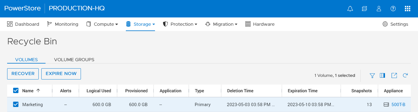
Figure 4 – Recycle Bin view
Configuration of the Recycle Bin expiration duration applies throughout the whole PowerStore cluster. By default, the expiration duration value is set to 7 days, but it can be set to range anywhere from 0–30 days. Note that resources placed in the Recycle Bin consume storage capacity and count against the PowerStore appliance limits.
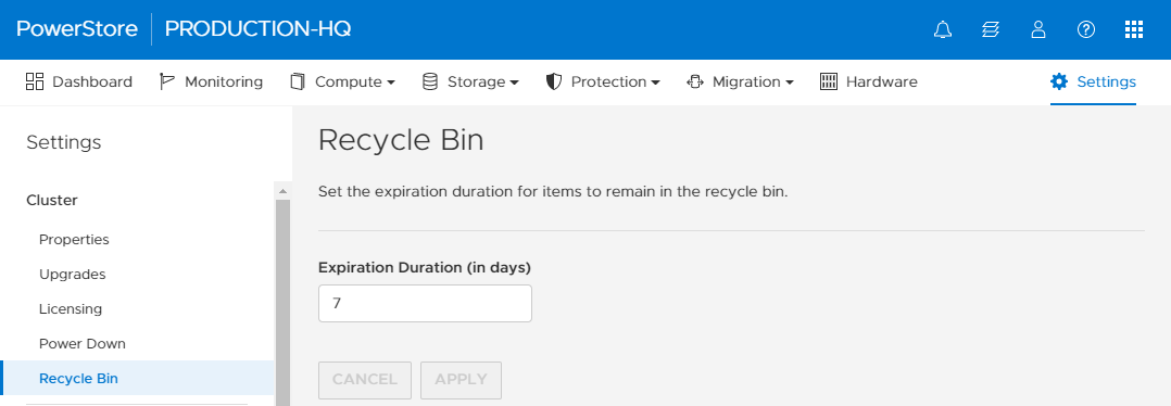
Figure 5 – Settings > Cluster > Recycle Bin
Conclusion
Data is the core component of your organization. It’s what makes your business operational, which is why it is imperative to protect it. We’ve all had those difficult days at work, and mistakes can happen. It’s great to have technology that is forgiving when those errors occur. I hope this blog gave you a quick glimpse of Dell PowerStore Recycle Bin’s resilience and how it can benefit your organization.
Resources
For more information, check out these resources:
Author: Louie Sasa, Senior Engineering Technologist

PowerStore and RSA SecurID – Solving your Multi-Factor Authentication Requirements
Thu, 08 Jun 2023 16:30:18 -0000
|Read Time: 0 minutes
PowerStore authentication overview
Previous versions of PowerStore supported basic or single factor authentication for both local and LDAP users. With growing security concerns in the global environment, many users are constantly looking to improve their security posture. The PowerStoreOS 3.5 release helps meet this goal by implementing multi-factor authentication support.
Improved security and authentication in PowerStoreOS 3.5
The new PowerStoreOS 3.5 release supports multi-factor authentication (MFA) with RSA SecurID. Multi-factor authentication, also known as advanced or two-factor authentication, provides an additional layer of security when logging into or performing functions on the system. It is a core component of a strong identity and access management (IAM) policy, which is critical to many organizations in today’s security climate.
Multi-factor authentication provides a higher security posture and has many advantages. It increases the security of accounts and data against hackers, mitigates the risks of poor password practices, and helps users stay compliant with regulations.
PowerStore’s multi-factor authentication software integrates with RSA SecurID, an authentication product that validates the identity of a user before allowing them access. Many users all over the world already leverage RSA for their intranet, so this release makes it easy to use that same infrastructure with PowerStore. Figure 1 shows how easy it is to configure and discover your RSA authentication manager from within PowerStore Manager.
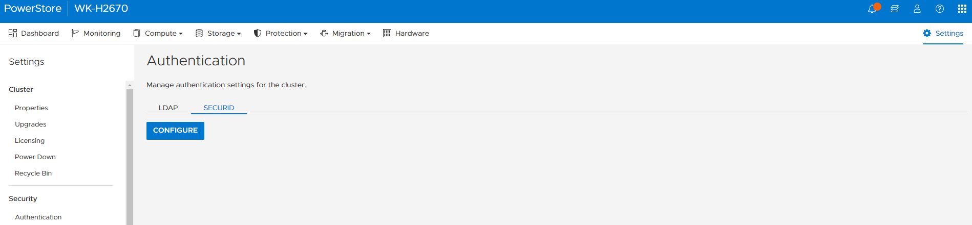
Figure 1. Configure and Discover RSA authentication manager
Here you click the Configure button and enter your RSA SecurID Server settings as shown in Figure 2. The required information is the Server IP or FQDN, Client ID (PowerStore cluster IP), and the access key created in your RSA server.
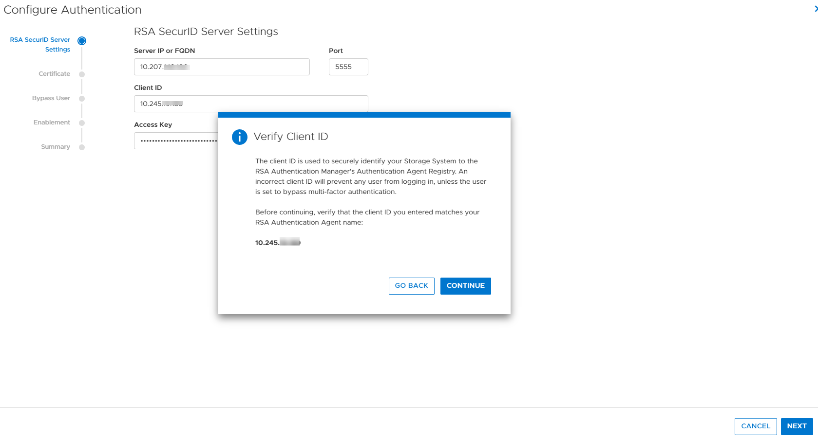
Figure 2. RSA SecurID Server settings
Next, you simply browse for your RSA certificate file or paste it into the box as shown in Figure 3. The RSA certificate file and access key that you enter help ensure secure communications between the RSA authentication manager and PowerStore.
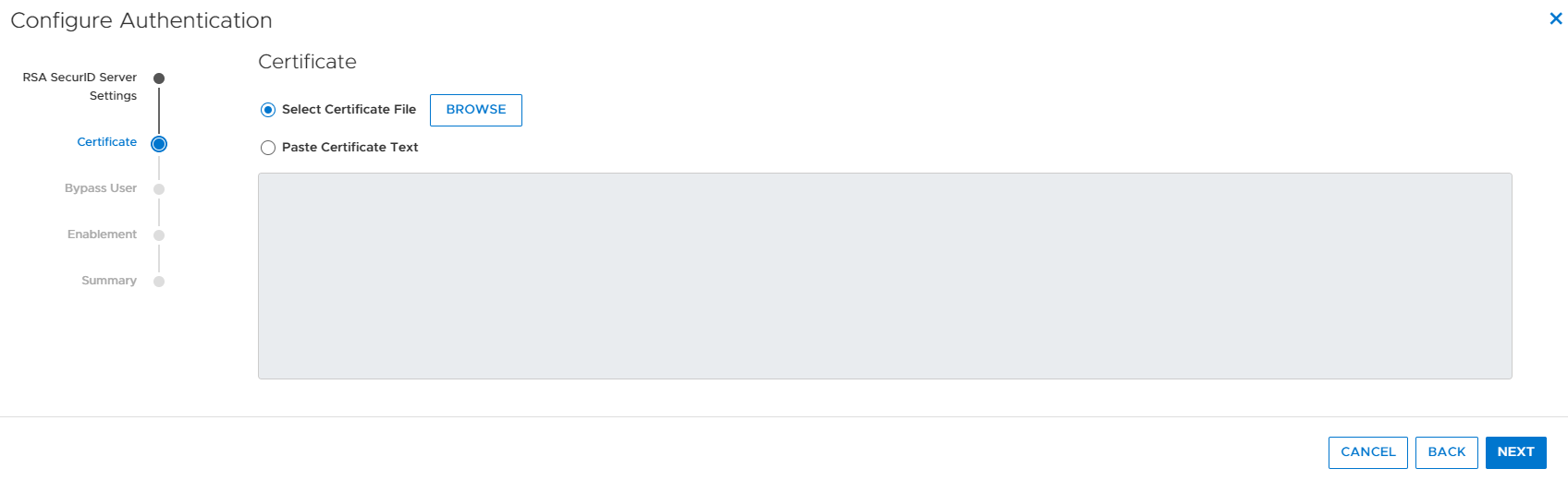
Figure 3. RSA certificate
The next step in the authentication wizard is to configure a bypass user if desired. Selecting and configuring a bypass user (Figure 4) allows a user to have the ability to bypass the RSA MFA login process. It is highly recommended to choose a local administrator for this purpose in case you lose access to the SecurID authentication manager. If this happened and you didn’t have a valid bypass user, you wouldn’t be able to log into the PowerStore system. A service script also allows the service user to manually bypass users, if the need arises.
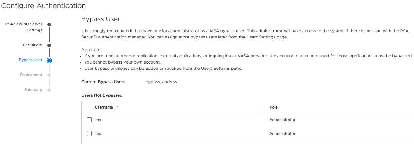
Figure 4. Bypass user
Then, you decide in the wizard if you want to enable MFA with RSA right away, or enable it manually later, see Figure 5. If you choose to enable RSA SecurID right away, you will be logged out of PowerStore Manager and be required to login with MFA RSA authentication.
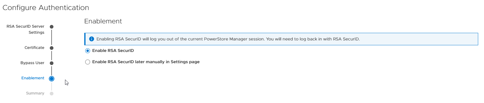
Figure 5. Enable RSA SecurID
Finally, you review your configuration settings and click Configure (Figure 6),
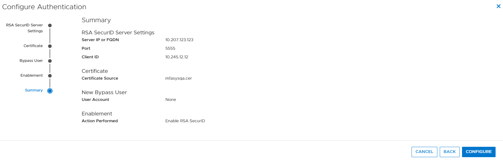
Figure 6. Configure Authentication summary
Now when you log in using MFA with RSA enabled on your PowerStore system, you log in as normal with single factor username and password authentication as shown in Figure 7, but will be prompted for the RSA SecurID passcode afterwards, as shown in Figure 8. This multi-factor authentication provides the additional security many customers and their infrastructures require. Note that this feature works with LDAP authentication as well as local users.
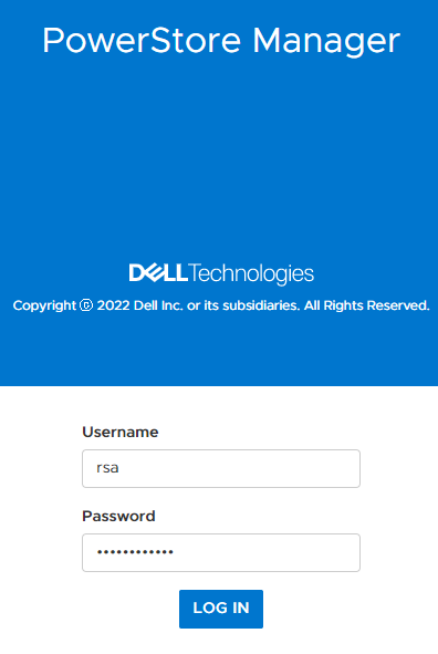
Figure 7. Single factor login
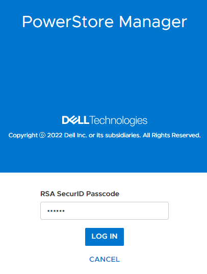
Figure 8. MFA with RSA SecurID login
Conclusion
I hope this blog gave you a quick glimpse into how easy it is to set up and use multi-factor authentication with RSA SecurID on PowerStore to increase your organization’s security posture.
Resources
For additional information about the features described in this blog, and other information about the PowerStoreOS 3.5 release, see the following:
Other resources
- What’s New In PowerStoreOS 3.5?
- Dell Technologies Main Info Hub
- Dell Technologies PowerStore Info Hub
- PowerStore: Info Hub - Product Documentation & Videos
- Dell PowerStore Hands-on Labs
Author: Andrew Sirpis

Time to Rethink your SQL Backup Strategy – Part 2
Wed, 10 May 2023 15:17:38 -0000
|Read Time: 0 minutes
A while back, I wrote a blog about changes to backup/restore functionality in SQL Server 2022: SQL Server 2022 – Time to Rethink your Backup and Recovery Strategy. Now, more exciting features are here in PowerStoreOS 3.5 that provide additional options and enhanced flexibility for protecting, migrating, and recovering SQL Server workloads on PowerStore.
Secure your snapshots
Backup copies provide zero value if they have been compromised when you need them the most. Snapshot removal could happen accidentally or intentionally as part of a malicious attack. PowerStoreOS 3.5 introduces a new feature, secure snapshot, to ensure that snapshots can't be deleted prior to their expiration date. This feature is a simple checkbox on a snapshot or protection policy that protects snapshots until they expire and can't be turned off. This ensures that your critical data will be available when you need it. Secure snapshot can be enabled on new or existing snapshots. Here’s an example of the secure snapshot option on an existing snapshot.
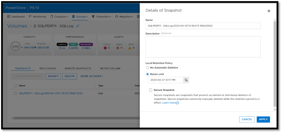
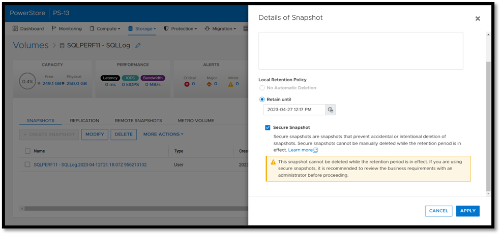
Once this option is selected, a warning is displayed stating that the snapshot can’t be deleted until the retention period expires. To make the snapshot secure, ensure that the Secure Snapshot checkbox is selected and click Apply.
Secure snapshot can be applied to individual snapshots of volumes or volume groups. The secure snapshot option can also be enabled on one or more snapshot rules in a protection policy to ensure that snapshots taken as part of the protection policy have secure snapshot applied.
Since existing snapshots can be marked as secure, this option can be used on snapshots taken outside of PowerStore Manager or even snapshots taken with other utilities such as AppSync. Consider enabling this option on your critical snapshots to ensure that they are available when you need them!
There's no such thing as too many backups!
If you're responsible for managing and protecting SQL Server databases, you quickly learn that it's valuable to have many different backups and in various formats, for various reasons. It could be for disaster recovery, migration, reporting, troubleshooting, resetting dev/test environments, or any combination of these. Perhaps you’re trying to mitigate the risk of failure of a single platform, method, or tool. Each scenario and workflow has different requirements. PowerStoreOS 3.5 introduces direct integration with Dell PowerProtect DD series appliances, including PowerProtect DDVE which is the virtual edition for both on-premises and cloud deployments. This provides an agentless way to take crash consistent, off-array backups directly from PowerStore and send them to PowerProtect DD.
To enable PowerStore remote backup, you need to connect the PowerProtect DD appliance to your PowerStore system as a remote system.
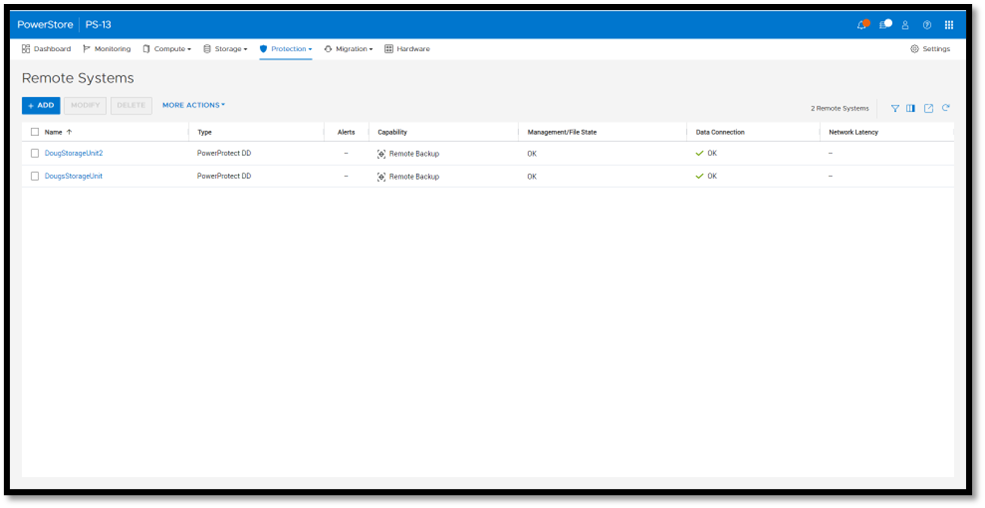
Next, you add a remote backup rule to a new or existing protection policy for the volume or volume group you want to protect, providing the destination, schedule, and retention.
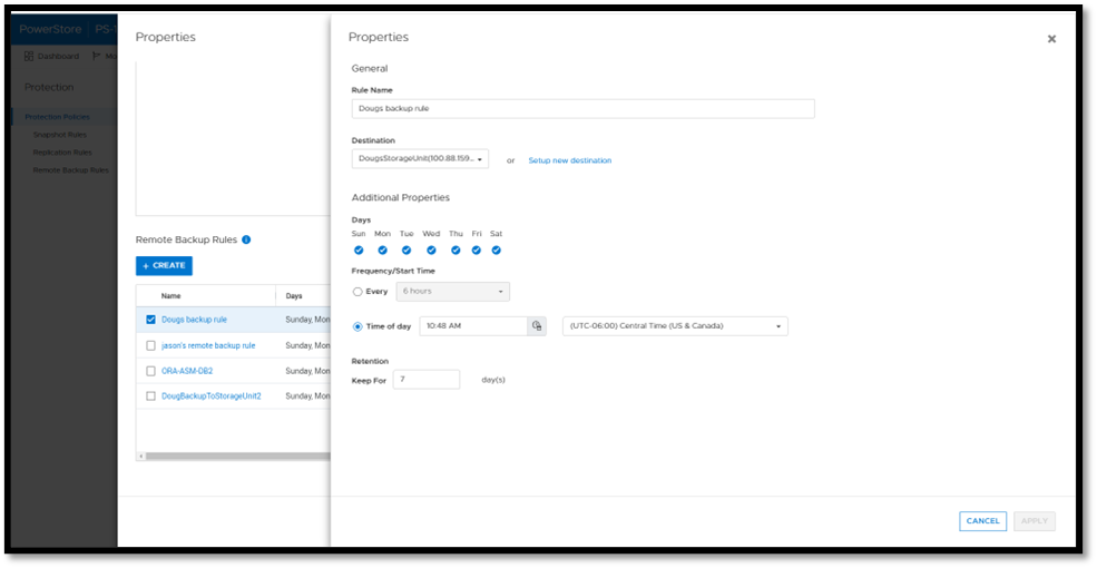
Once a protection policy is created with remote backup rules and assigned to a PowerStore volume or volume group, a backup session will appear.
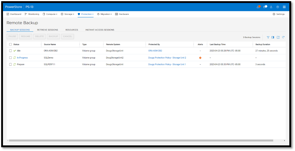
Under Backup Sessions, you can see the status of all the sessions or select one to back up immediately, and click Backup.
Once a remote backup is taken, it will appear under the Volume or Volume Group Protection tab as a remote snapshot.
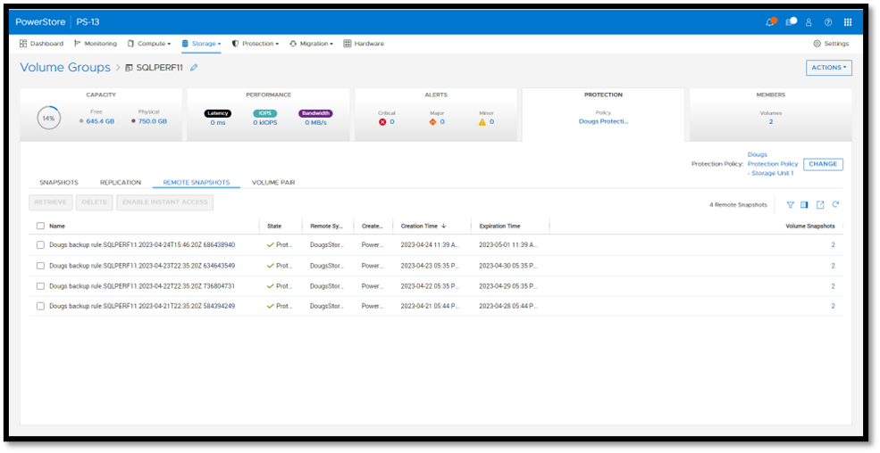
From here, you can retrieve it and work with it as a normal snapshot on PowerStore or enable Instant Access whereby the contents can be accessed by a host directly from PowerProtect DD. You can even retrieve remote snapshots from other PowerStore clusters!
This is yet another powerful tool included with PowerStoreOS 3.5 to enhance data protection and data mobility workflows.
For more information on this feature and other new PowerStore features and capabilities, be sure to check out all the latest information on the Dell PowerStore InfoHub page.
Author: Doug Bernhardt
Sr. Principal Engineering Technologist
https://www.linkedin.com/in/doug-bernhardt-data/

Dell PowerStore Native Integration with Dell PowerProtect DD Series Appliances for DP in Oracle Environments
Wed, 10 May 2023 13:29:40 -0000
|Read Time: 0 minutes
Having many years of production database experience, I know DBAs will be eager to give this new capability a try.
PowerStoreOS 3.5 has just been released and with it comes more data protection capabilities. This translates into a more robust arsenal of tools and capabilities for the DBA’s tool kit. The feature provides a way to quickly backup, restore, and thinly provision database clones for different environments from a remote data source!
There are several data protection enhancements added to PowerStoreOS 3.5. One that excites me is a native backup solution that integrates with remote data storage appliances: Dell PowerProtect DD series appliances.
Integration with PowerProtect DD series appliances
The native integration from PowerStore to PowerProtect DD series appliances allows DBAs to create a crash consistent backup image of a database in the form of a remote snapshot. Administrators can initiate this remote snapshot directly from PowerStore Manager with a remote connection to a PowerProtect DD appliance. Because the snapshot is created directly on the PowerProtect DD appliance, no additional storage is consumed on PowerStore, making this backup strategy storage efficient. This close integration significantly streamlines the process of transmitting backups to the remote PowerProtect DD Series appliance by eliminating the need for a dedicated backup host, and reduces time and complexity.

This removes the worries of having to work with other types of remote storage, including tape, for your Oracle crash consistent images!
Remote Backup Rules
New to PowerStoreOS 3.5 is a new protection rule called a Remote Backup Rule, which sets a schedule by which remote snapshots are taken. The rule allows users to create remote crash consistent Oracle database snapshots on a PowerProtect DD Series appliance.
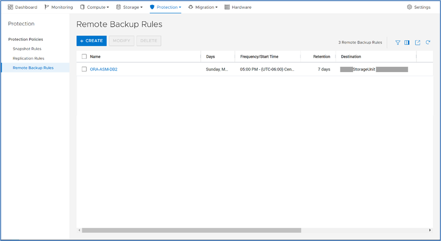
A Remote Backup Rule can be scheduled for any day of the week with a frequency of every 6, 12, or 24 hours, or at a specific time of day. The default retention period for the remote snapshots is 7 days but can be configured up to 70 years!
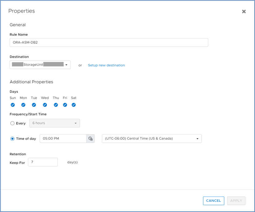
After a Remote Backup Rule is created, it can be added to a protection Policy. In the following figure, remote backup rule ORA-ASM-DB2 has been added to the ORA-ASM-DB2 protection policy.
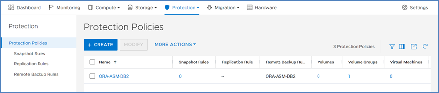
After the remote backup rule is added to a protection policy, the protection policy can be assigned to the storage resource used by the Oracle database, such as a volume group with write-order consistency enabled. The following figure shows that the PowerStore volume group ORA-ASM-DB2 is assigned the ORA-ASM-DB2 protection policy.
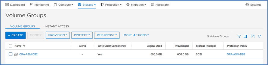
Remote snapshots will now be automatically generated, based on the defined schedule in the remote backup rule ORA-ASM-DB2.
Creating remote snapshots
Creating remote snapshots are just clicks away! To create a remote snapshot manually, select Protection, then Remote Backup. Click BACKUP SESSIONS, select the desired backup session, then click BACKUP. That’s all that’s needed to create the snapshot on the remote PowerProtect DD appliance.
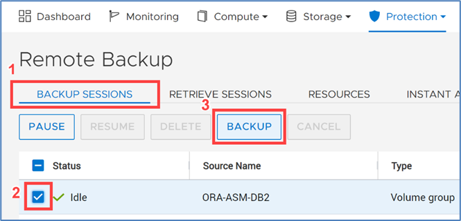
Effortless retrieval of remote backups of Oracle databases
The PowerStoreOS 3.5 retrieve option has several use cases. Here I’ll mention two. One is to retrieve a remote snapshot for a currently existing PowerStore resource and restore it. Another is to create a thin clone of the PowerStore resource from the retrieved remote snapshot. For Oracle databases, the PowerStore resource is the PowerStore Volume Group that contains the volumes that are hosting the Oracle database.
To retrieve a remote snapshot for a volume group, it’s as simple as six mouse clicks from the Remote Backup feature!:
RESOURCES --> select the PowerStore resource --> MANAGE SNAPSHOTS:
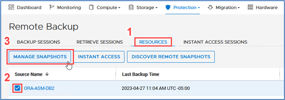
Select the remote snapshot --> RETRIEVE --> RETRIEVE:
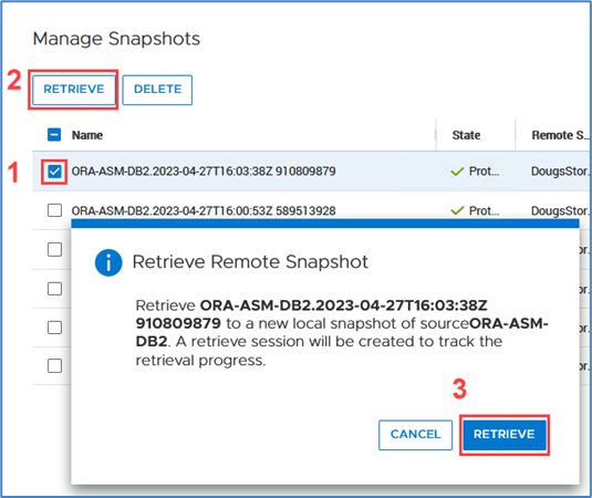
When the PowerStore storage resources have been recovered by the snapshot, simply start the Oracle database and Oracle does the rest with crash recovery.
Conclusion
PowerStoreOS 3.5 provides enhanced data protection features that simplify the DBA’s tasks of taking backups, recoveries, restores, and cloning databases with a few mouse clicks. DBAs will find this feature a great tool for their toolkit.
PowerStoreOS 3.5 is truly a game changer! This new data protection capability is just one of the numerous features introduced in PowerStoreOS 3.5. Be sure to keep an eye out for additional blog posts that showcase these valuable features.
Author: Mark Tomczik

Dell VxRail and Dell PowerStore: Better Together Through Dynamic AppsON
Fri, 05 May 2023 16:29:52 -0000
|Read Time: 0 minutes
Dynamic AppsON overview
When two products come together with new and unique capabilities, customers benefit from the “better together” value that is created. That value is clearly visible with Dynamic AppsON, which is a configuration that provides an exclusive integration between compute-only Dell VxRail dynamic nodes and a Dell PowerStore storage system.
Dynamic AppsON enables independent scaling of compute and storage, providing flexibility of choice by increasing the extensibility of both platforms. It provides VxRail environments access to PowerStore enterprise efficiency, data protection, and resiliency features. Additionally, it helps PowerStore environments quickly expand compute for CPU-intensive workloads in a traditional three-tier architecture.
Another integration point that further enhances the Dynamic AppsON experience is the Virtual Storage Integrator (VSI). VSI brings storage provisioning, management, and monitoring capabilities directly into vCenter. It enables the ability to perform common storage tasks and provides additional visibility into the storage system without needing to launch PowerStore Manager.
With Dynamic AppsON, you have the flexibility to choose the type of datastore and connectivity that fits your environment. Dell Technologies recommends vVols and NVMe/TCP.
Leveraging the native vVol capabilities of PowerStore is the optimal way to provision VM datastores. This enables increased storage granularity at the VM level, offloading of data services to PowerStore, and storage policy-based management directly in vCenter. This further enables vCenter as the common operating environment for the administrator.
For connectivity, NVMe/TCP is recommended because it provides significant advantages. It enables performance that is comparable to direct-attach, while retaining the cost-effectiveness, scalability, and flexibility of traditional Ethernet.
Figure 1. Dynamic AppsON overview
For more information about Dynamic AppsON, see the Dell VxRail and Dell PowerStore: Better Together Through Dynamic AppsON white paper.
.
Dynamic AppsON lifecycle management
Dell VxRail and Dell PowerStore have taken this integration a step further by introducing lifecycle management for Dynamic AppsON deployments. This enables an administrator to view the PowerStore details and initiate a code upgrade directly from VxRail Manager in vCenter. By leveraging the VxRail Manager user interface and workflows, an administrator does not need to switch between multiple interfaces for the lifecycle management operations.
The lifecycle management functionality from VxRail Manager is exclusively enabled through VSI. Dynamic AppsON lifecycle management is available starting with VxRail 7.0.450, PowerStoreOS 3.0, and Virtual Storage Integrator (VSI) 10.2.
Dynamic AppsON lifecycle management provides the following capabilities in VxRail Manager in vCenter:
- View the attached storage system type and software version
- Upload a code bundle from the local client directly to PowerStore
- Run a Pre-Upgrade Health Check on PowerStore and report any warnings and failures
- Initiate a code upgrade and track the progress until completion
The following figures show these Dynamic AppsON lifecycle management tasks in VxRail Manager.
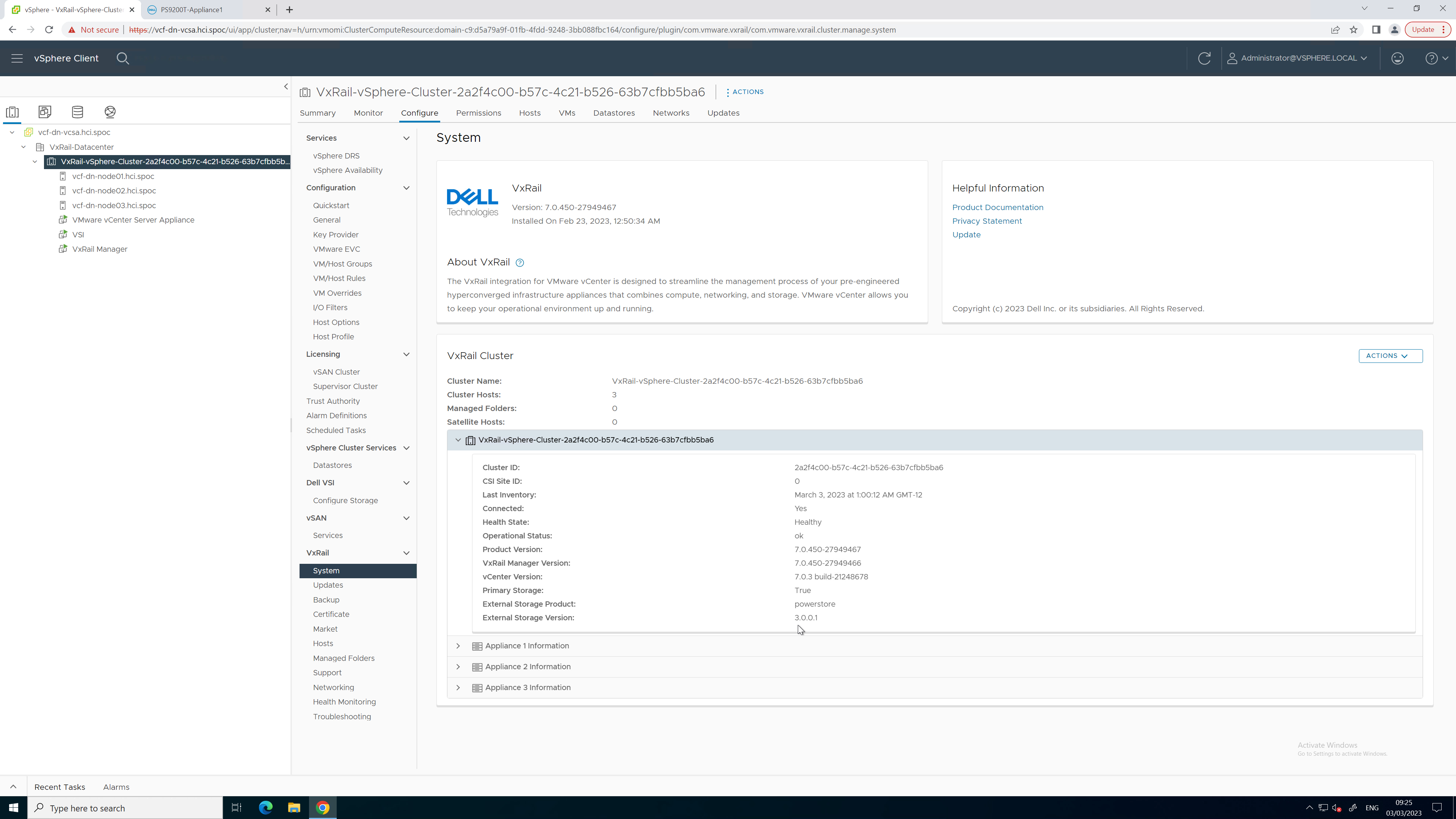
Figure 2. PowerStore code reporting
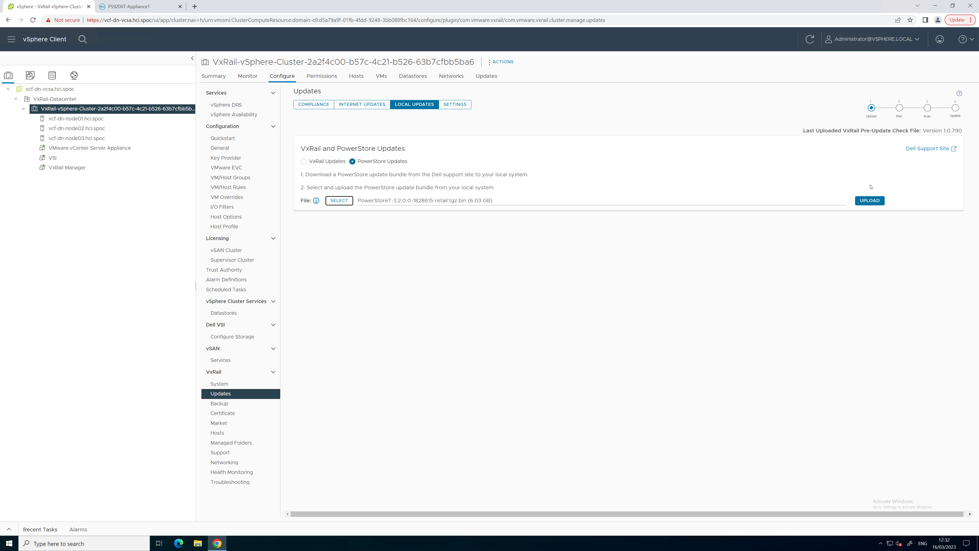
Figure 3. PowerStore code upload
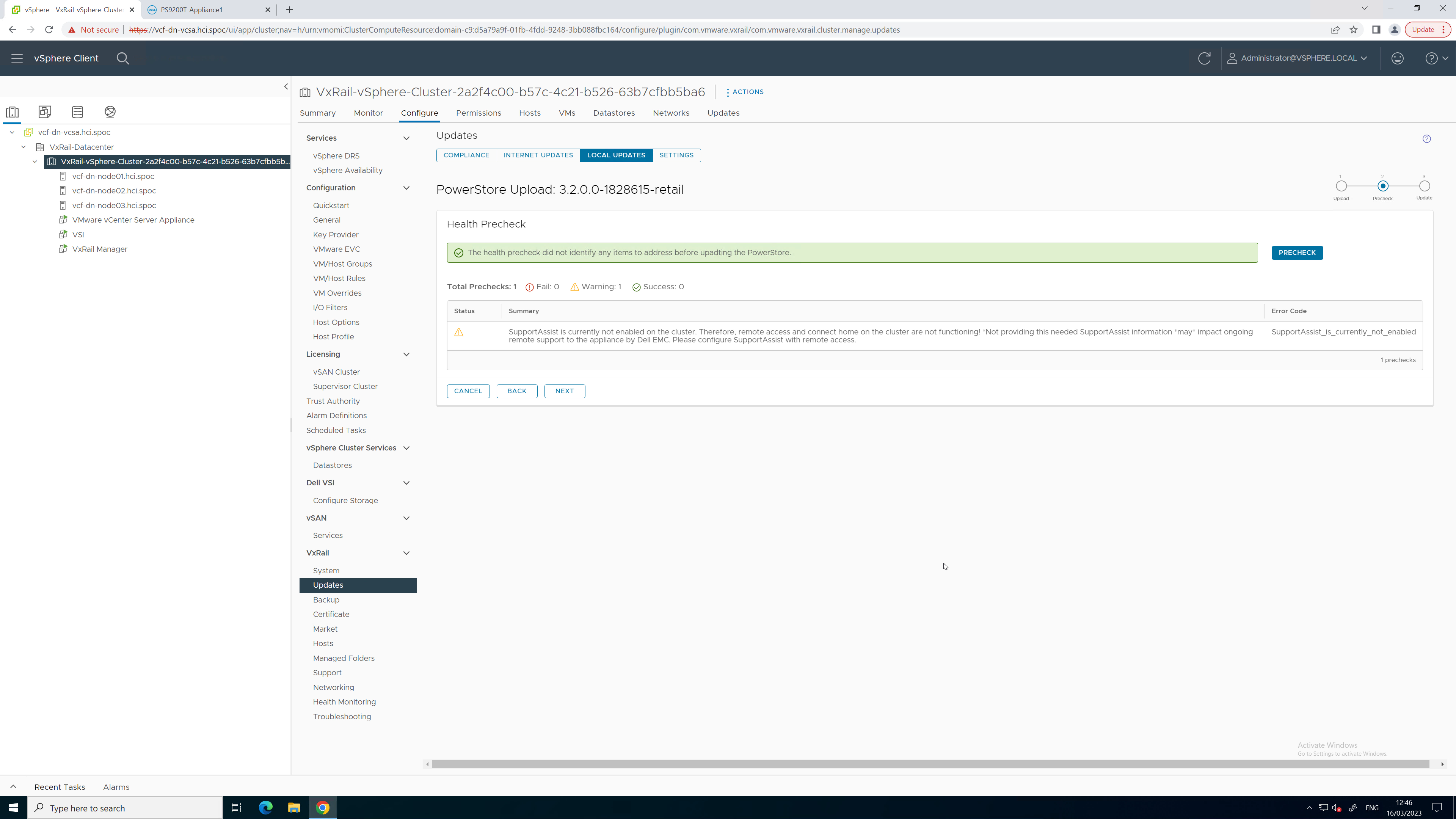
Figure 4. PowerStore Pre-Upgrade Health Check
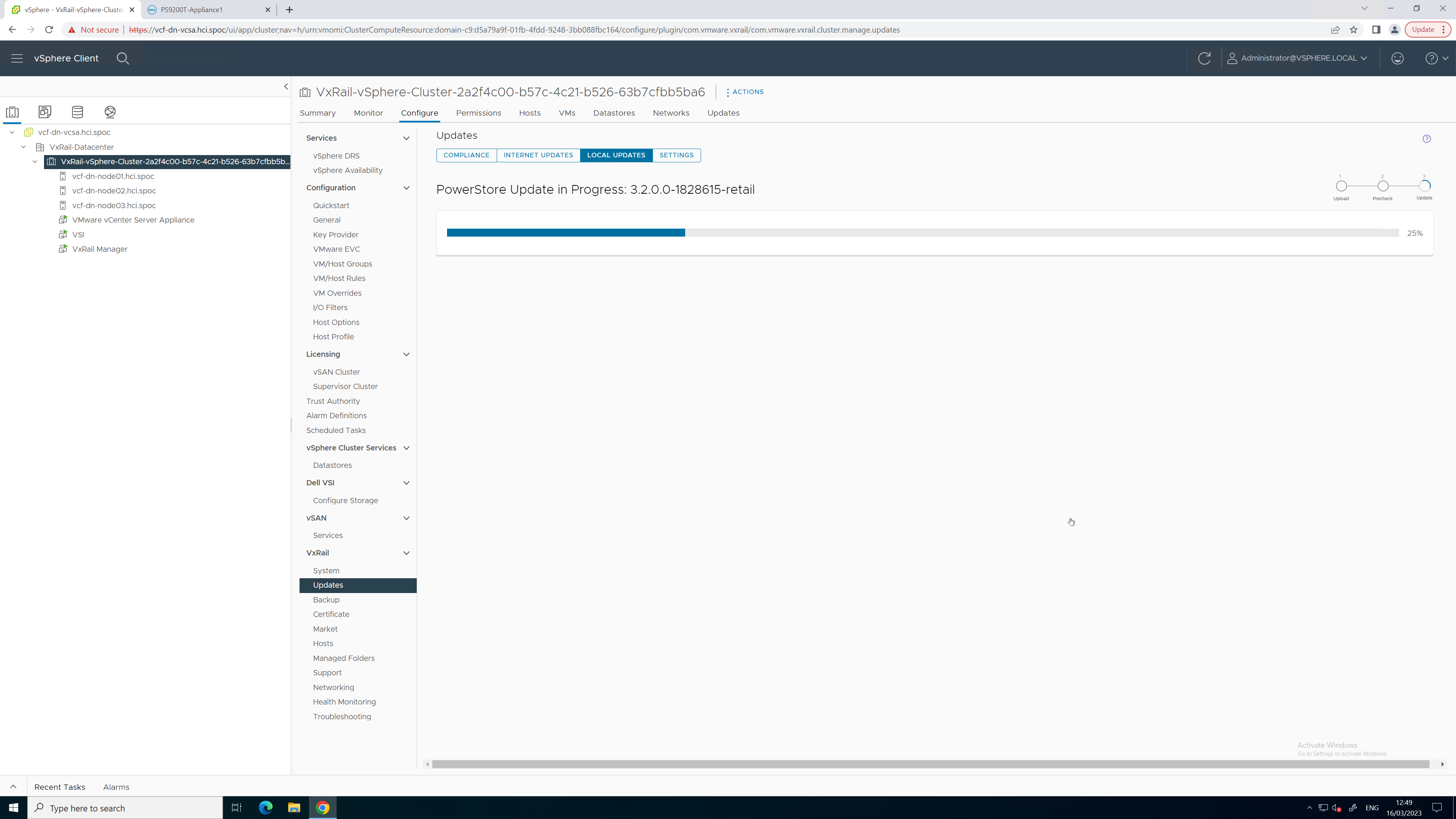
Figure 5. PowerStore upgrade in progress
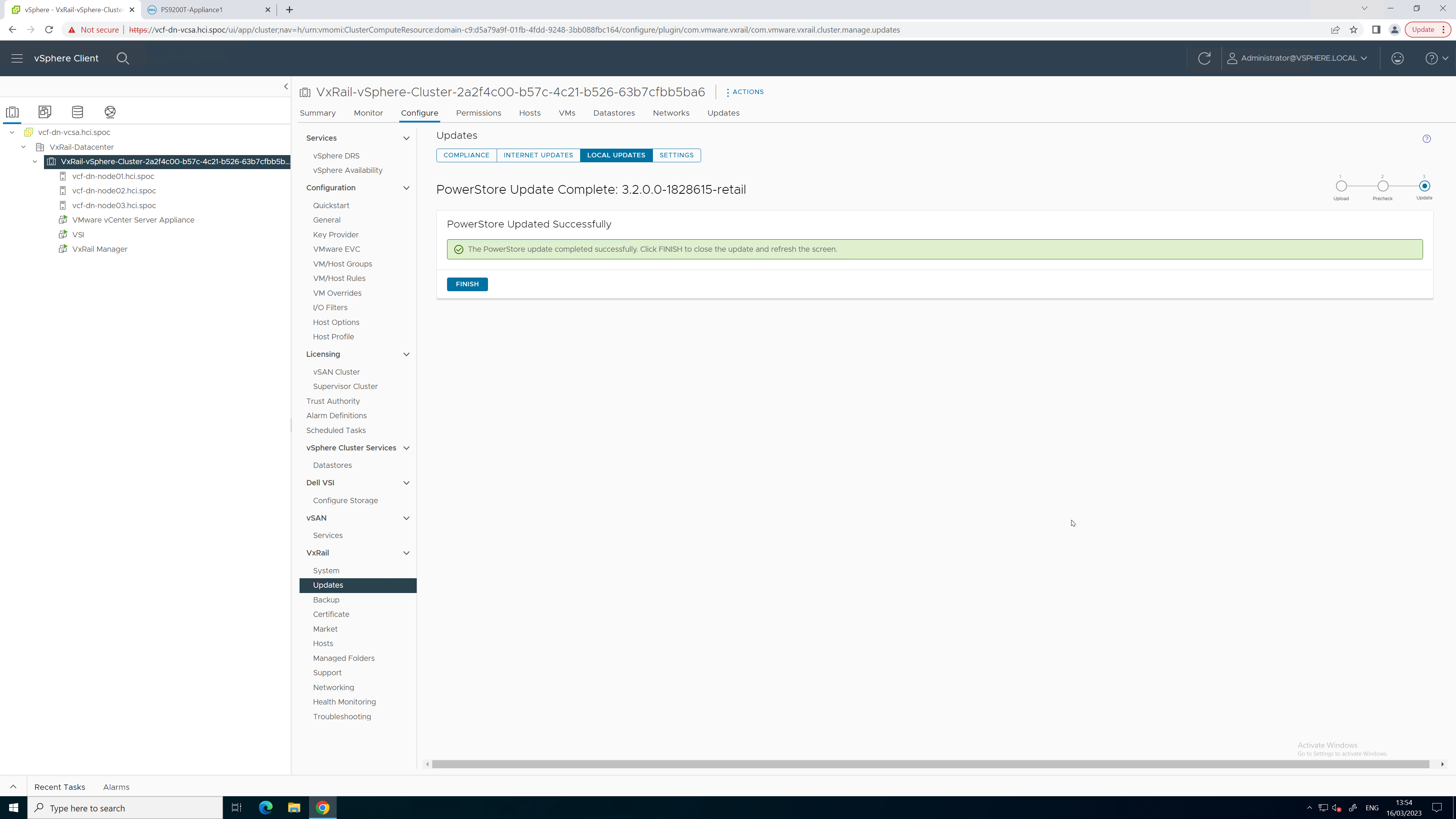
Figure 6. PowerStore upgrade completed successfully
Figure 7. Updated PowerStore code version
To see all these lifecycle management tasks in action from start to finish, refer to this video:
Conclusion
With the addition of lifecycle management for Dynamic AppsON, the number of storage management tasks for which a virtualization and storage administrator has to leave vCenter is reduced. This functionality provides a consistent, common, and efficient management experience for both VxRail and PowerStore. The integration between VxRail, PowerStore, and the VSI plug-in enables consistent workflows and visibility between storage and compute. Better together through Dynamic AppsON, brought to you by Dell VxRail and Dell PowerStore.
Resources
- Dynamic AppsON Lifecycle Management video
- Dynamic AppsON Summary video
- Dynamic AppsON infographic
- Dynamic AppsON: A Better Together Story blog
- Dell VxRail and Dell PowerStore: Better Together Through Dynamic AppsON white paper
- Dell PowerStore: Virtualization Integration white paper
Author: Wei Chen, Technical Staff, Engineering Technologist

Dell PowerStore – Easily Create a Metro Volume in Six Clicks
Thu, 04 May 2023 20:12:42 -0000
|Read Time: 0 minutes
In this short blog, I’ll walk you through the configuration of a metro volume and prove that it’s possible to enable a metro session in just six clicks, when the remote system and a standard volume are already setup.
A metro volume is a volume that runs a bi-directional synchronous replication between two different sites. Hosts using either side of a metro volume get active-active simultaneous access on both sides of the metro volume. The use case for a PowerStore metro volume is a vSphere Metro Storage Cluster (also known as a stretched cluster configuration) with VMware vSphere.
PowerStore metro volumes support a latency maximum of 5ms and a maximum distance of 80miles/100km. After the operator sets up a metro volume, PowerStore internally creates a metro session to control the replication between the two sites. When the remote system relationship is set up on PowerStore, and the volume is mapped to one or more hosts, it requires just six additional clicks to set up a metro session for a standard volume, as shown here:
1. Select the volume. 2. Navigate to PROTECT. 3. Select Configure Metro Volume.
|
|
4. Click the pull down to select the remote system. 5. Select the remote system. 6. Click CONFIGURE |
|
To mitigate any performance impact on the source system for the new, unsynchronized metro volume, PowerStore immediately starts with asynchronous replication and switches into synchronous replication once the data is in sync. |
|
Because a metro session replicates all IO synchronously, active-active host access is possible on both ends of the metro volume. Even during the initial synchronization, hosts can map the new volume on the replication destination but only get active paths when the metro session is in an active-active state.
|
|
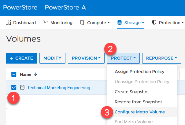
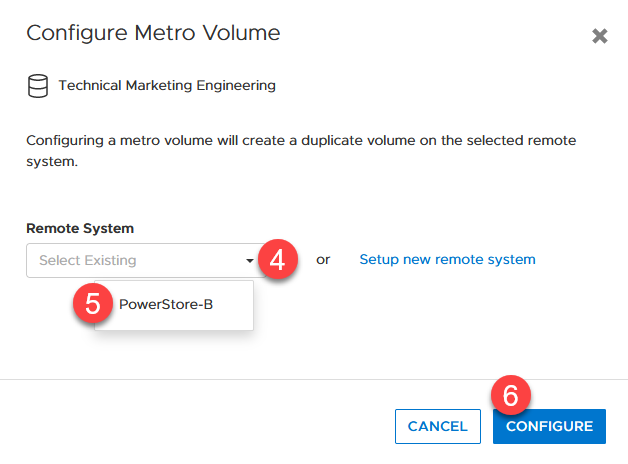
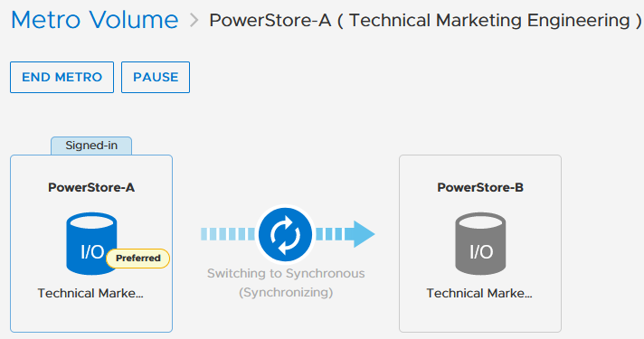

When hosts are in a uniform configuration, active paths are provided by both participating PowerStore clusters. The following example shows a uniformly connected host that can access the metro volume in two storage networks (fabrics).
Here is the mapping of individual NICs in this example:
ESXi Host | NIC 1 | PowerStore-A | Node A Node B | C0:T0:L2 (Active I/O) C0:T1:L2 |
|
| PowerStore B | Node A Node B | C0:T2:L2 C0:T3:L2 |
| NIC2 | PowerStore-A | Node A Node B | C1:T0:L2 (Active I/O) C1:T1:L2 |
|
| PowerStore B | Node A Node B | C1:T2:L2 C1:T3:L2 |
Resources
Author: Robert Weilhammer, Principal Engineering Technologist
https://www.xing.com/profile/Robert_Weilhammer

What's New in PowerStore OS 3.5?
Fri, 19 May 2023 16:56:13 -0000
|Read Time: 0 minutes
Dell PowerStoreOS 3.5 is the latest software release for the Dell PowerStore platform. In this release, there has been a large focus on data protection and security for PowerStore T as well as File networking, scalability, and more. We’ll cover all of these in this blog!
The following list highlights the major features to expect in this software release followed by additional details for each category.
- Security: On the security side of the house, we’ve implemented support for Multi-Factor Authentication (MFA) for PowerStore Manager and REST API using RSA SecurID. Following the US Federal Security Technical Guide conditions, PowerStore now complies with STIG requirements. Also, users can now import a 3rd party certificate for the VMware VASA provider.
- Data Protection: We’ve added a few different enhancements to our data protection capabilities: the largest feature is a native backup solution that integrates with Dell PowerProtect DD series appliances. Metro Volume has seen some UI enhancements to help guide customers on selecting appropriate host connectivity options. The new secure snapshot setting protects snapshots from being accidentally or maliciously deleted.
- File Enhancements: Through PowerStore Manager and REST, users can now manage file share permissions (ACLs). Fail-Safe Networking (FSN) can be created for NAS server interfaces, a lightweight and switch-agnostic form of link redundancy that complements link aggregation.
- Scaling & Capacity: We’ve improved scalability limits for file systems, volumes, and vVols. We’ve also added a Recycle Bin for retrieving deleted volumes, volume groups, and snapshots within an expiration period.
Security
Multi-Factor Authentication
Multi-Factor Authentication (MFA), also known as two-factor authentication, has become a modern-day standard not only in the datacenter, but in our everyday lives. In PowerStoreOS 3.5 and later, users can now enable MFA for PowerStore Manager and REST API. Once configured using your existing RSA Authentication Manager, users have two-factor authentication with LDAP users or PowerStore manager users using their RSA SecurID token.
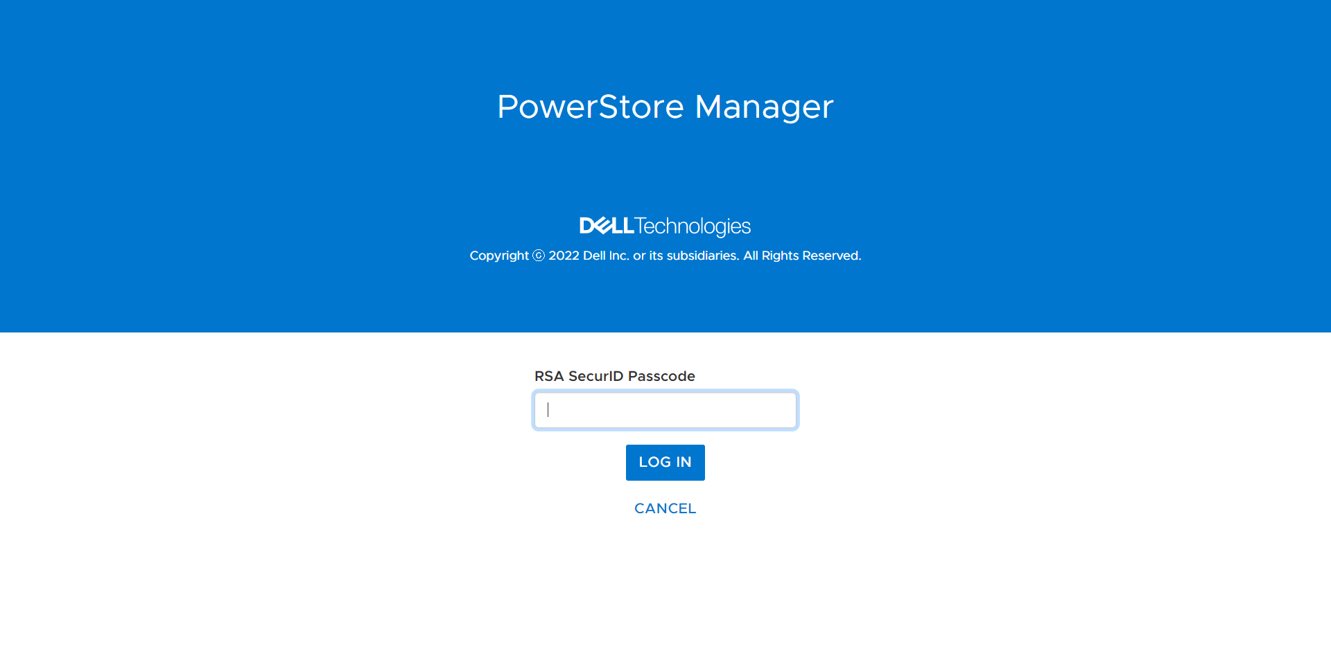
Security Technical Implementation Guides (STIG compliance)
STIG mode is an optional setting that implements security configuration changes to harden the existing appliance all the way down to PowerStore’s base OS and containers. Having STIG compliance is typically a requirement for US Federal customers and dark sites alike. STIG compliance is also a prerequisite for the Approved Product List (APL) certification which is a standard for Department of Defense (DoD) organizations.
With Multi-Factor Authentication, Secure Snapshots, and STIG compliance, PowerStore is hardened to accommodate the security requirements of the US Federal Government and Zero Trust security environments.
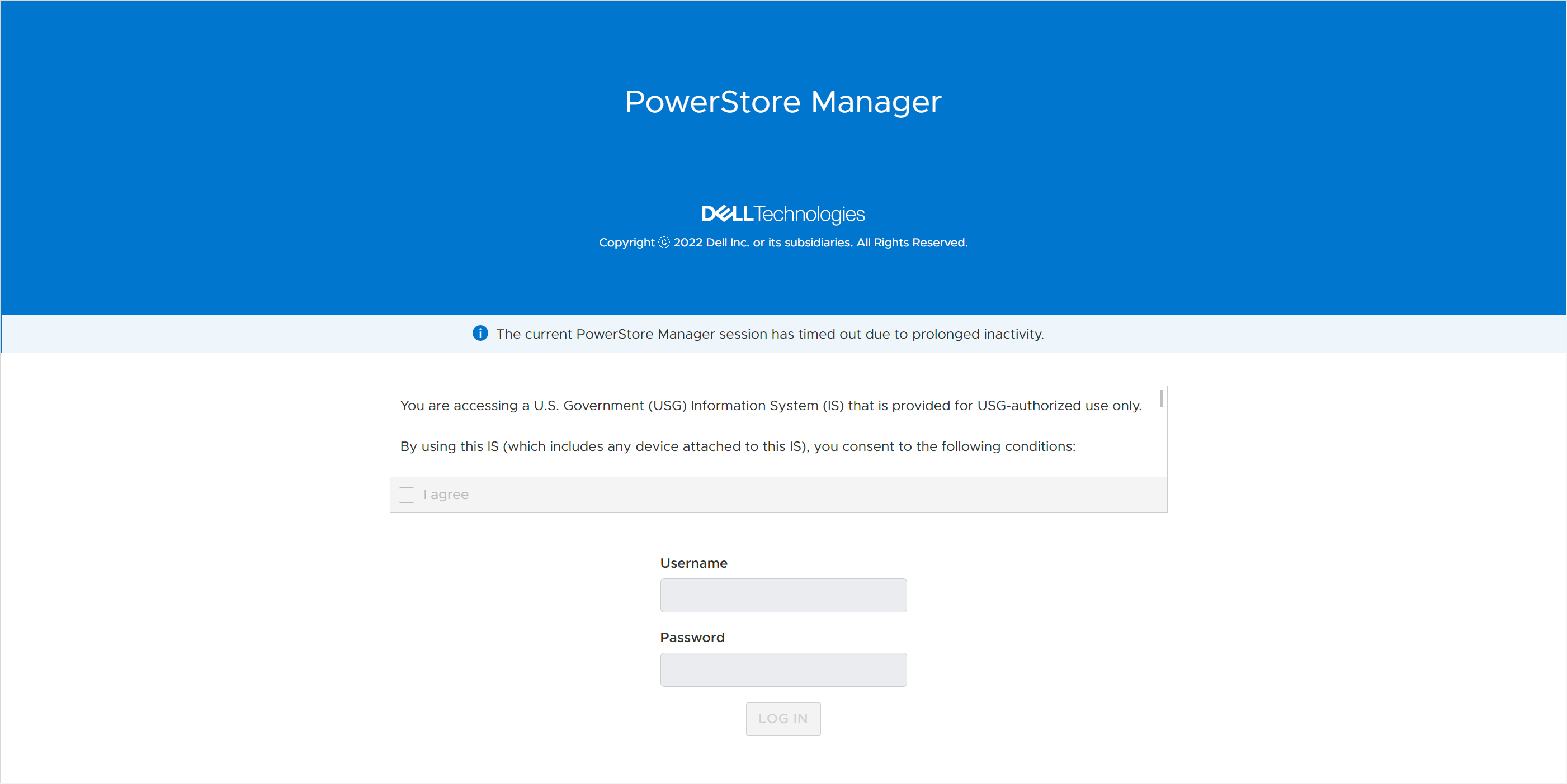
Data Protection
Native PowerProtect DD Backup Integration
Studies show that using a backup and storage solution from a single vendor can reduce data protection administration costs by up to 22%. Using PowerStore’s native PowerProtect integration, backups in the form of remote snapshots can be initiated directly from PowerStore Manager using a remote connection to the PowerProtect DD appliance (physical or virtual edition). Users can set up cloud or on-prem backup in just 90 seconds natively within PowerStore Manager. PowerStore enables faster backups through tight integration with PowerProtect DD Appliances, enabling the ability to back up to 150TB daily.
Backups can be initiated manually or through a new protection rule called a Remote Backup Rule. Users can create remote backup sessions, retrieve snapshots, recover deleted or corrupted resources, and provide hosts with access to snapshots directly on the PowerProtect appliance. This host access, called Instant Access, provides access to data from a remote PowerProtect appliance in just seven clicks from a single UI.
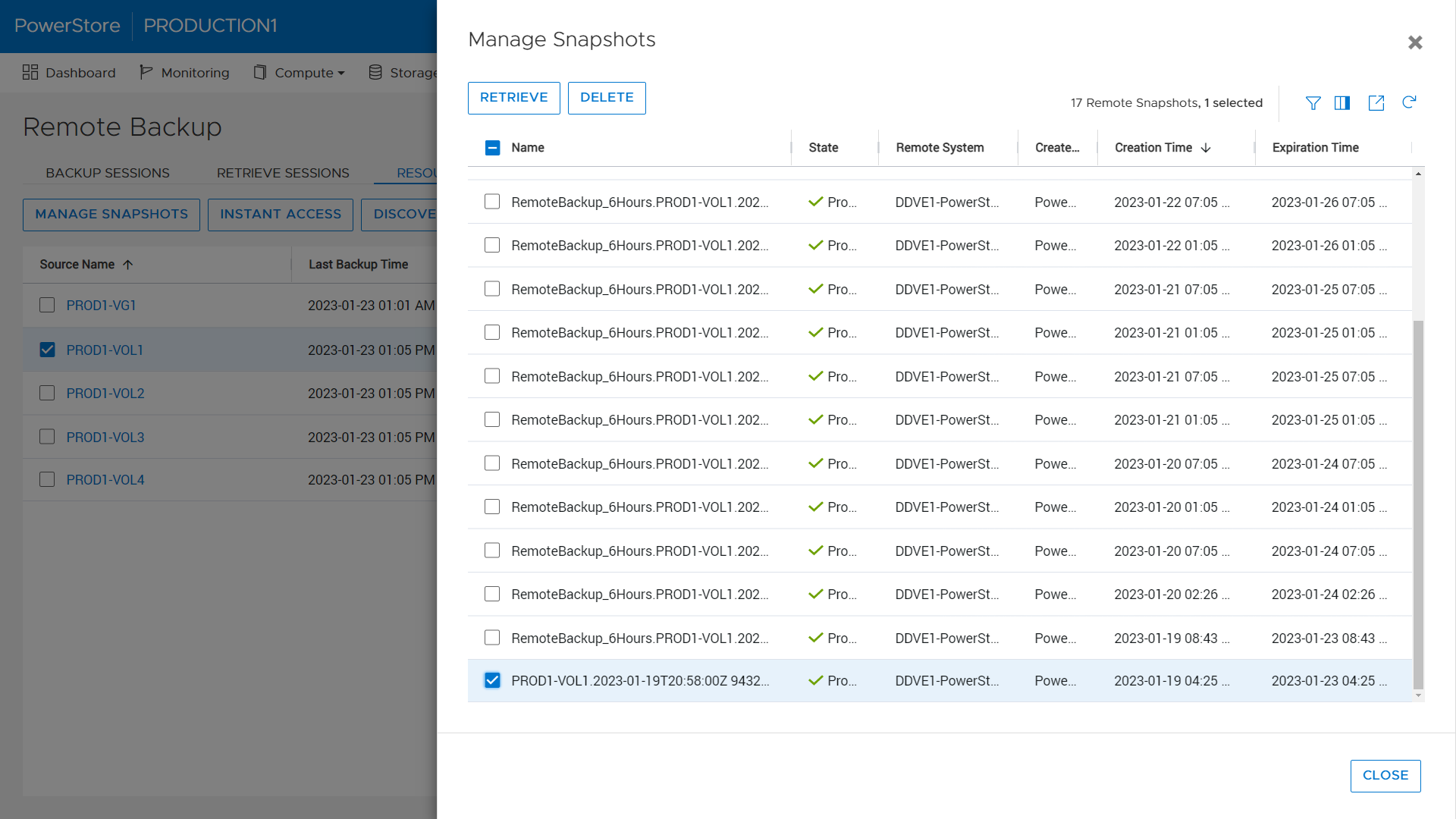
Metro Volume
Native Metro Volume, PowerStore’s synchronous active/active block replication technology introduced in PowerStoreOS 3.0, has been updated to include graphical representation of the host’s connectivity during setup to help users pick the right configuration. These configurations are Local Connectivity (also known as non-uniform), where the host is only connected to the local PowerStore appliance, and Metro Connectivity (known as uniform), where the host has connections to both local and remote PowerStore appliances. When selecting metro connectivity, the UI helps guide the user through the different connectivity options:
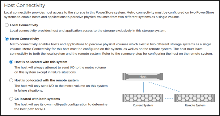
Secure Snapshots
The Secure Snapshot setting is an optional setting for volume and volume group snapshots. When the Secure Snapshot setting is enabled, the snapshot is protected from deletion until the retention period expires. The Secure Snapshot option also cannot be disabled on a snapshot after it is enabled. This provides a cost-effective line of defense against ransom attacks and accidental deletion of snapshots, volumes, or volume groups. Secure snapshots can also be created automatically using a Protection Policy containing a Snapshot Rule with the Secure Snapshot option enabled. The Secure Snapshot option within the Snapshot Rule can be enabled or disabled at any time. Changing this setting only affects future snapshot creations.
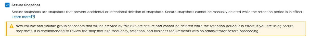
File enhancements
SMB share permissions (ACLs)
When provisioning a NAS share usingthe SMB protocol, the share permissions are managed from the client within an Access Control List (ACL). With PowerStoreOS 3.5, these permissions within the ACL can be managed directly from PowerStore Manager or REST API. Leveraging this feature, PowerStore users can define and manage existing share permissions without requiring access to the client-side environment.
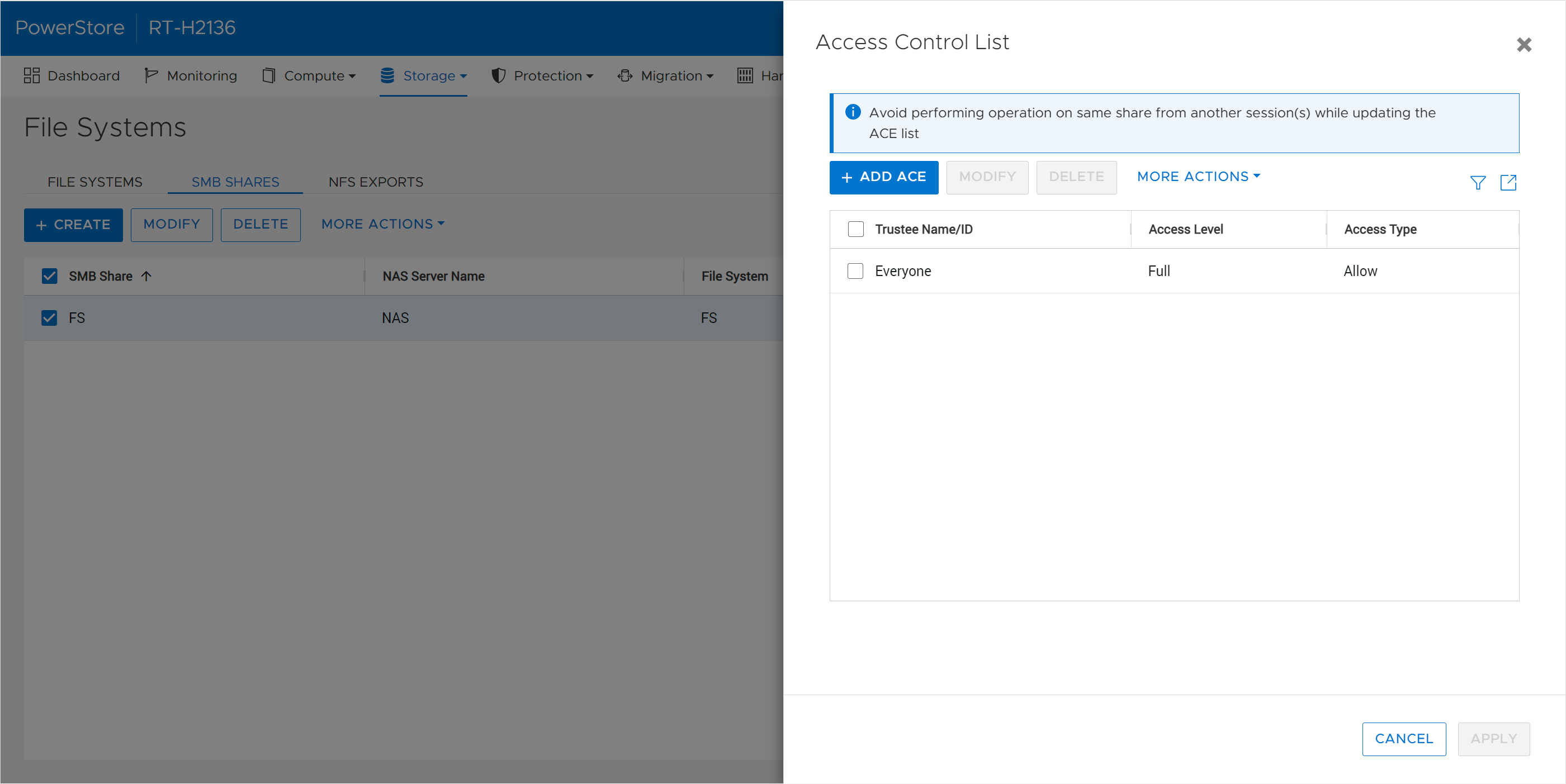
Fail-Safe Networking (FSN)
Fail-Safe Networking is a well-known feature used in other products across the Dell portfolio, such as Unity XT, which provides a mechanism for switch-level redundancy. You may ask if this is needed since PowerStore already supports Link Aggregation (LA). Fail-Safe Networking provides a high availability solution that is switch agnostic for NAS interfaces. With FSN, users can eliminate single points of failure (ports, cables, switches, and so on) by linking ports together in an active/passive configuration. An FSN can consist of individual ports, Link Aggregations, or a combination of both. When used in conjunction with LA, multiple ports can be used as part of the active or backup part of the FSN.
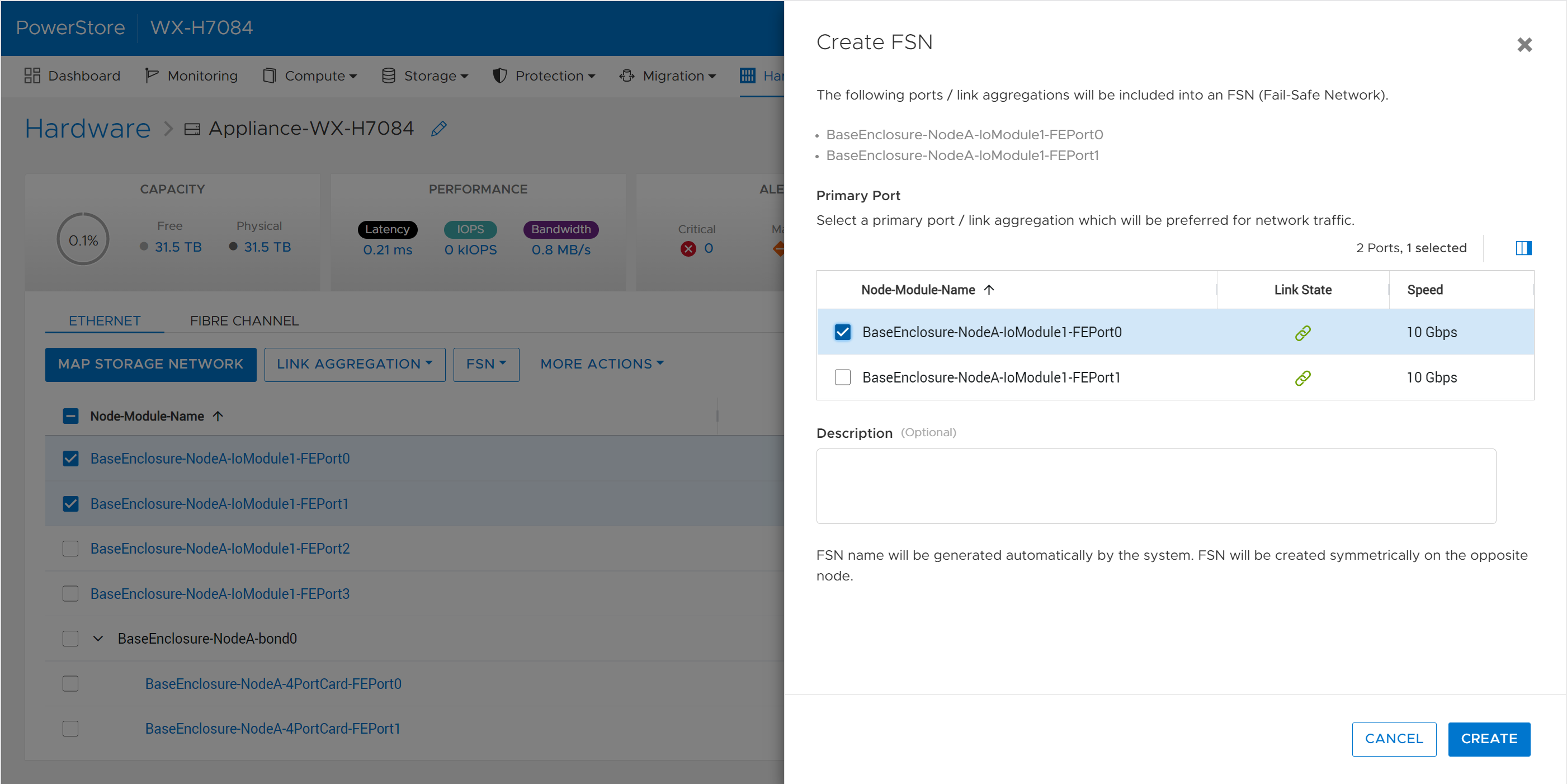
Scalability and Capacity
File, volume, and vVol limit increase
Across the board, PowerStoreOS 3.5 brings increased limits to the number to file systems, volumes, and vVols that can be provisioned. The amount that the limits have increased for each of these resources depends on the PowerStore model. A few examples: the number of NAS servers for the PowerStore 3200 and higher is increased from 50 to 250 NAS servers per appliance. On a PowerStore 9200, the combined max number of volumes, vVols, and file systems is now 16,600 per appliance. There are also up to 4x the number of .snapshot files and file systems that can be provisioned. For a full list of resource limits on PowerStore, check out the support matrix.
Recycle bin
Research indicates that human error proves to be the most common cause of data loss - typically in the form of accidental deletion of data, unorganized data, or administrative errors. In the PowerStoreOS 3.5 release, we’ve introduced a recycle bin feature to combat accidental deletion of block storage resources. If a block resource is deleted, it will enter the recycle bin by default. The recycle bin is located in the Storage > Recycle Bin section of PowerStore Manager. In there, users can view, restore, and permanently expire volumes, volume groups, and their corresponding snapshots. Users can also customize the expiration period from 0-30 days depending on their requirements.
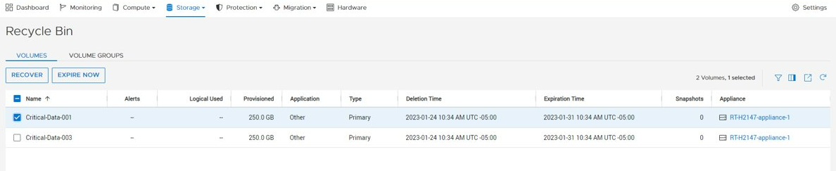
Conclusion
The PowerStoreOS 3.5 release offers a multitude of enhancements across the board for the PowerStore product. In the modern data center, PowerStore continues to deliver on security, data protection, and scalability with the performance of an end-to-end NVMe platform. It’s no wonder that PowerStore is deployed in over 90% of Fortune 500 vertical sectors and rated #1[1] in customer satisfaction!
Resources
For additional information about the features above, along with other information about the PowerStoreOS 3.5 release, consult the whitepaper and solution documents found below:
- Data Protection for PowerStore with PowerProtect DD Series Appliances
- Dell PowerStore Native Integration with Dell PowerProtect DD Series Appliances for DP in Oracle Environments
- Time to Rethink your SQL Backup Strategy – Part 2
- Dell PowerStore: Snapshots and Thin Clones
- Dell PowerStore: Cybersecurity
- Dell PowerStore: File Capabilities
- Dell PowerStore: Persistent Data Availability
- Dell PowerStore: Metro Volume
- Dell PowerStore: Microsoft SQL Server Best Practices
- Dell PowerStore: Oracle Best Practices
- Dell PowerStore: Microsoft Hyper-V Best Practices
- Dell PowerStore: MongoDB Solution Guide
- Dell PowerStore: VMware vSphere Best Practices
- Dell PowerStore: VMware vSphere with Tanzu and TKG Clusters
- Dell VxRail and Dell PowerStore: Better Together Through Dynamic AppsON
Other Resources
- What’s New In PowerStoreOS 3.2?
- PowerStore Simple Support Matrix
- PowerStore: Info Hub - Product Documentation & Videos
- Dell Technologies PowerStore Info Hub
Authors: Ryan Meyer and Ryan Poulin
[1] Based on Dell analysis in January 2022 comparing among Top 3 storage providers globally, using double-blinded, competitive benchmark Net Promoter Score (NPS) data gathered by third-party commissioned by Dell for 2H FY22.

Deploying VMware Cloud Foundation Workload Domains with PowerStore Systems
Wed, 22 Mar 2023 20:52:52 -0000
|Read Time: 0 minutes
Overview
VMware Cloud Foundation is a true hybrid cloud solution and provides an integrated software platform for customers. Dell Technologies has fully qualified PowerStore arrays as supplemental storage in VMware Cloud Foundation workloads.
This blog highlights how to deploy a three-node cluster within VMware Cloud Foundation and integrate it with Dell Technologies PowerStore systems.
Logical view of VMware Cloud Foundation
How to...
To begin the process, use SDDC (Software Defined Data Center) Manager to commission hosts.
When the hosts are unassigned and part of SDDC Manager, start deploying the virtual infrastructure workload domain. (We are using vVol in this lab.)
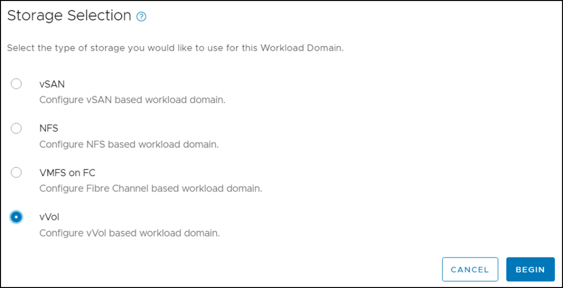
Provide the Virtual Infrastructure Name and Organization name.
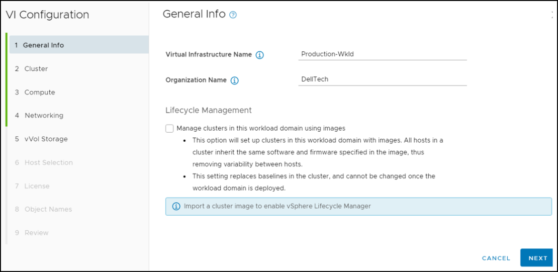
Enter the vCenter FQDN, IP address, subnet mask, gateway, and password information. This vCenter will manage the workload domain resources.
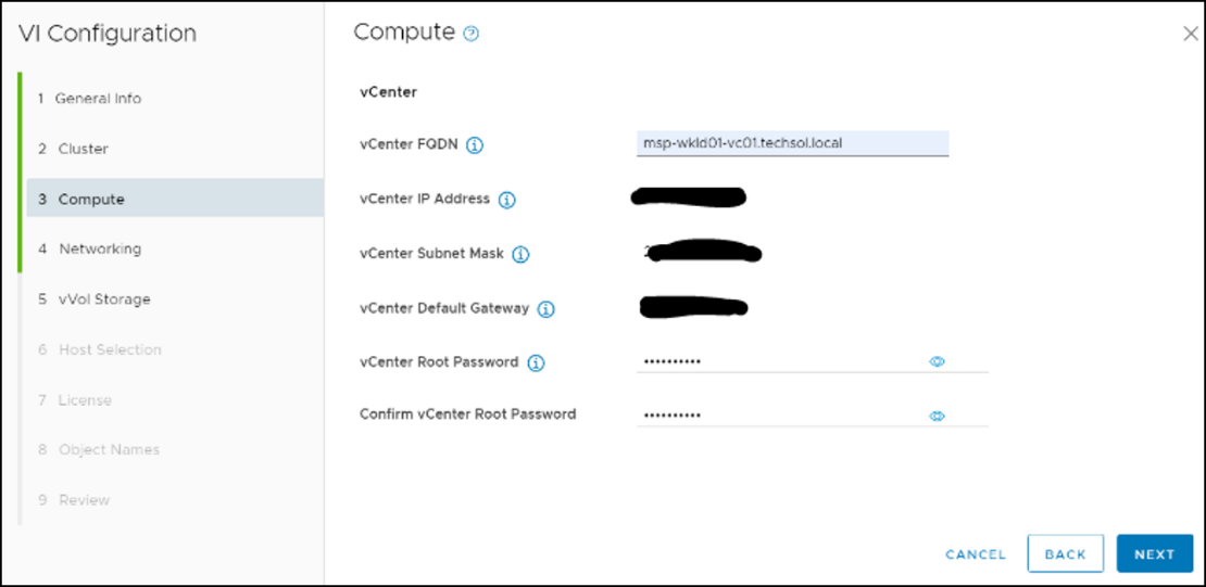
The next step is to specify the NSX-T networking parameters, including three NSX-T managers, the VIP, and overlay network. This requires all DNS records to be preconfigured.
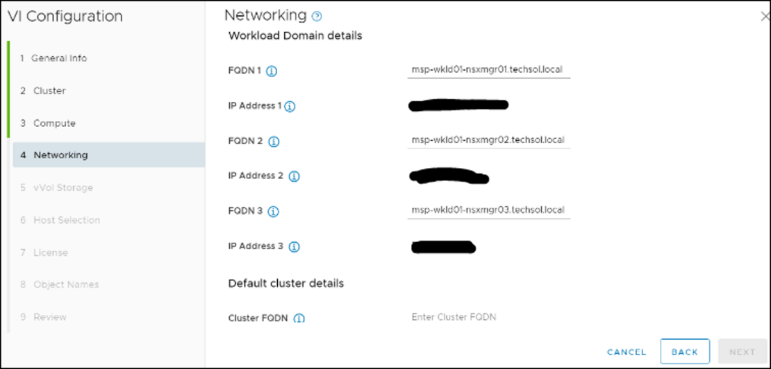
Specify the PowerStore vVol configuration, including the VASA provider and user.
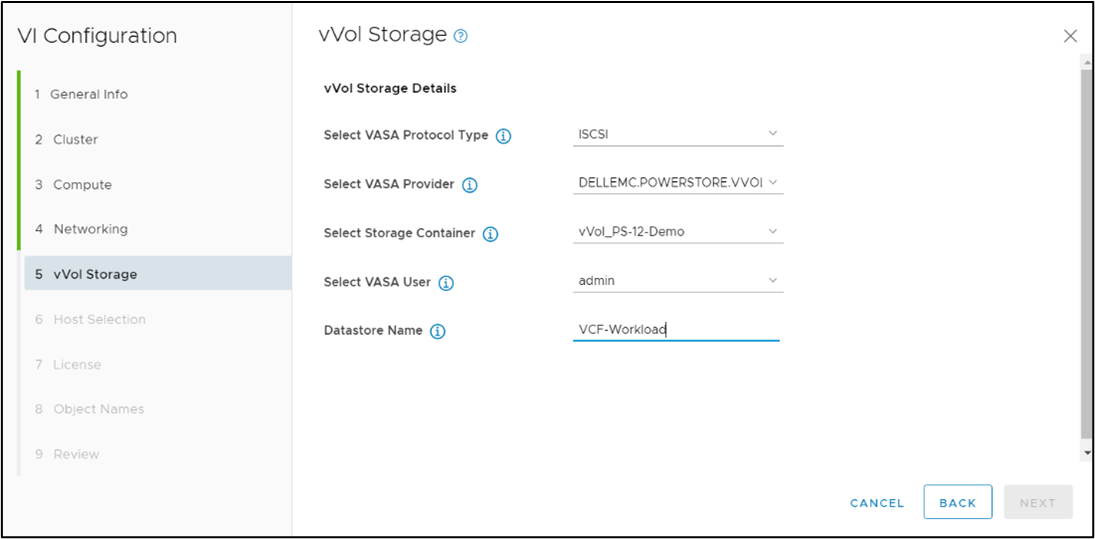
Select the hosts to use for this 3-node cluster.
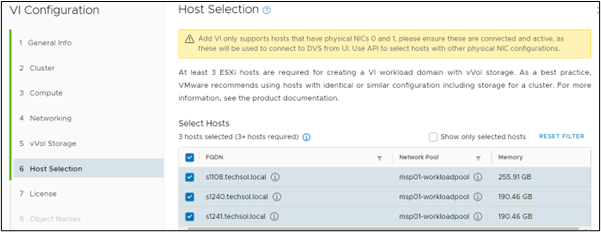
Select the licenses to apply for. Review the objects and summary, then select Finish to deploy.
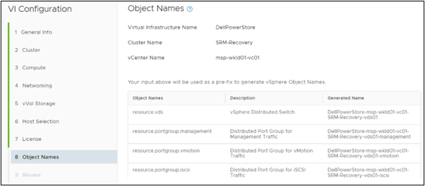
The tasks are running, creating the workload domain. If a task fails, SDDC Manager allows you to troubleshoot and continue the deployment.
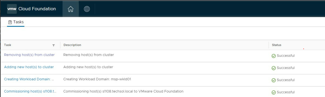
When the tasks are completed, SDDC Manager lists the workload domain.
From PowerStore Manager, the vVol is shown under the storage container with three ESXi hosts attached.
Conclusion
Dell PowerStore extends the boundaries of mid-range storage with unmatched capabilities for enterprise storage. PowerStore integrates seamlessly with VMware Cloud Foundation by delivering a platform that is secure, agile in cloud infrastructure, and easily consumed from a public or private cloud.
Resources
- PowerStore Product Documentation & Videos
- Dell Technologies PowerStore Info Hub
- VMware.com/products/cloud-foundation.html
Author: Jason Gates

PowerStore Revalidated with Microsoft Azure Arc-enabled Data Services
Mon, 27 Feb 2023 22:29:17 -0000
|Read Time: 0 minutes
Microsoft Azure Arc-enabled data services allow you to run Azure data services on-premises, at the edge, or in the cloud. Arc-enabled data services align with Dell Technologies’ vision, by allowing you to run traditional SQL Server workloads or even PostgreSQL on your infrastructure of choice. For details about a solution offering that combines PowerStore and Microsoft Azure Arc-enabled data services, see the white paper Dell PowerStore with Azure Arc-enabled Data Services.
Dell Technologies works closely with partners such as Microsoft to ensure the best possible customer experience. We are happy to announce that Dell PowerStore has been revalidated with the latest version of Azure Arc-enabled data services[1].
Deploy with confidence
One of the deployment requirements for Azure Arc-enabled data services is that you must deploy on one of the validated solutions. At Dell Technologies, we understand that customers want to deploy solutions that have been fully vetted and tested. Key partners such as Microsoft understand this too, which is why they have created a validation program to ensure that the complete solution will work as intended.
By working through this process with Microsoft, Dell Technologies can confidently say that we have deployed and tested a full end-to-end solution with Microsoft and validated that it passes all tests.
The validation process
Microsoft has published tests that are used in their continuous integration/continuous delivery (CI/CD) pipeline for partners and customers to run. For Microsoft to support an Arc-enabled data services solution, it must pass these tests. At a high level, these tests perform the following:
- Connect to an Azure subscription provided by Microsoft
- Deploy the components for Arc-enabled data services, including SQL Managed Instance and PostgreSQL server
- Validate K8s, hosts, storage, networking, and other infrastructure specifics
- Run Sonobuoy tests ranging from simple smoke tests to complex high-availability scenarios and chaos tests
- Upload results
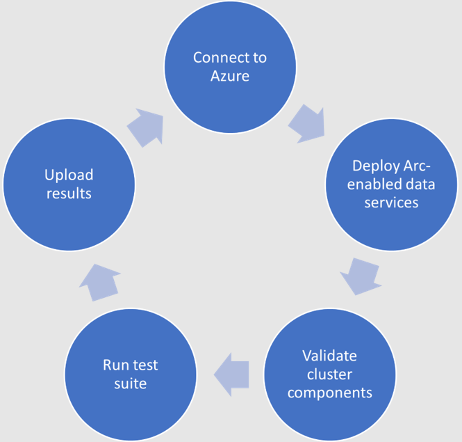
When Microsoft accepts the results, they add the new or updated solution to their list of validated solutions. At that point, the solution is officially supported. This process is repeated as needed as new component versions are introduced. Complete details about the validation testing and links to the GitHub repositories are available here.
More to come
Stay tuned for more additions and updates from Dell Technologies to the list of validated solutions for Azure Arc-enabled data services. Dell Technologies is leading the way on hybrid solutions, proven by our work with partners such as Microsoft on these validation efforts. Reach out to your Dell Technologies representative for more information about these solutions and validations.
Author: Doug Bernhardt, Sr. Principal Engineering Technologist
[1] Dell PowerStore T has been validated with v1.15.0_2023-01-10 of Azure Arc-enabled data services, published 1/13/2023, which is the latest version at the time of publishing.
PowerStore—The Power of Clustering
Mon, 27 Feb 2023 14:01:20 -0000
|Read Time: 0 minutes
Overview
PowerStore is designed to be a continuously modern storage platform. Its adaptable architecture allows for deploying appliances into a single- or multi-appliance cluster. Configuring a multi-appliance cluster with two to four appliances enables additional powerful functionality that you can be leveraging in your environment today!
PowerStore clustering capabilities are designed to simplify administration, provide integrated intelligence, and add flexibility, enabling multiple appliances to function as a single cohesive system. This blog discusses many of the benefits of deploying a multi-appliance cluster.
Simplicity
Configuring and managing a multi-appliance cluster is designed to be as simple as managing a single appliance. For both single- and multi-appliance clusters, storage administration is accomplished through a single user interface. The HTML5-based PowerStore Manager GUI provides an easy-to-use interface for management actions and monitoring operations that are crucial to an organization’s needs. There is no additional learning curve to manage your multi-appliance cluster.

Many PowerStore objects, such as protection policies, remote systems, vCenter and VASA provider connections, vVol storage containers, and hosts, exist at the cluster level. These objects can be used on all appliances, regardless of the size of the cluster. This alleviates the need to repeat operations on each appliance in the cluster.
For example, host registration for volume access needs to be completed just once. Hosts can be configured to have active initiators to one, some, or all appliances within the cluster, depending on your access requirements. This also enables volumes to be migrated between appliances within the cluster without any added management overhead. This can be used in situations such as if an appliance runs low on capacity, and when making service level changes, consolidating workloads, and more.
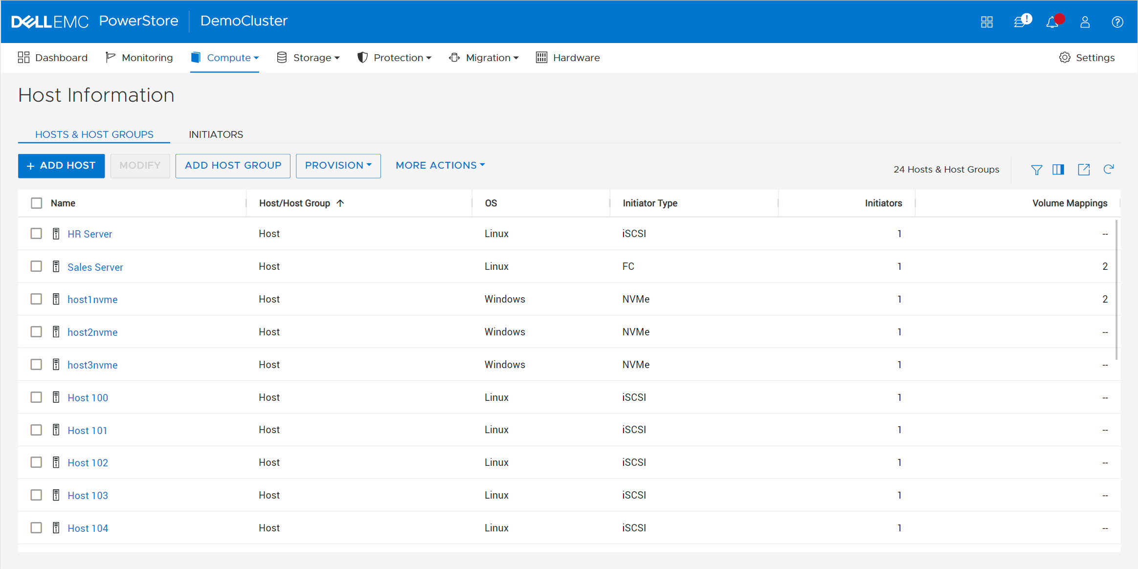
Most settings are also applied at the cluster level. These include PowerStoreOS code upgrades, security settings, network settings, user management, support materials, and more. Alerts, events, jobs, and audit logs are consolidated into a centralized area for all appliances in the cluster, eliminating the need to monitor each appliance individually. Performance and capacity metrics are available at the cluster, appliance, and resource levels. This provides the administrator with multiple levels of granularity needed for different tasks.
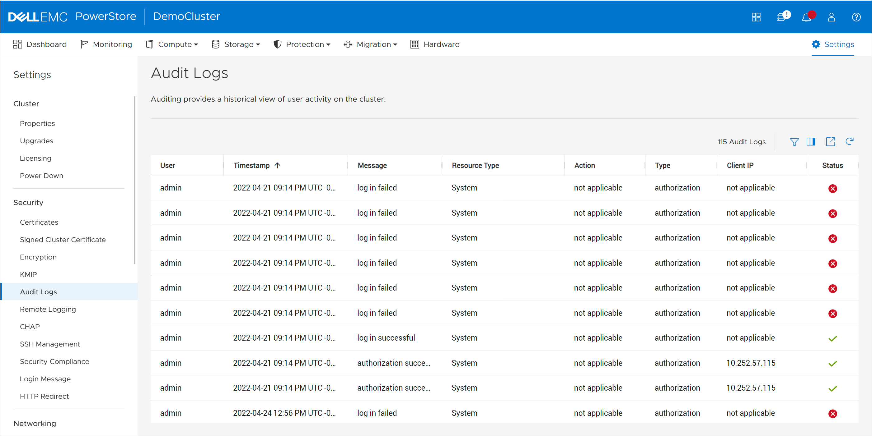
In multi-appliance configurations, each appliance has its own set of initiators for volume access. This level of granularity enables the highest level of control, providing the flexibility to connect specific hosts to specific appliances. However, if you want to connect a host to all appliances, you don’t need to go through the tedious effort of connecting to each appliance individually. PowerStore offers the option to configure a Global Storage Discovery IP address. This is a single, global, floating storage IP address that can be used to discover all paths for all the appliances in the cluster.
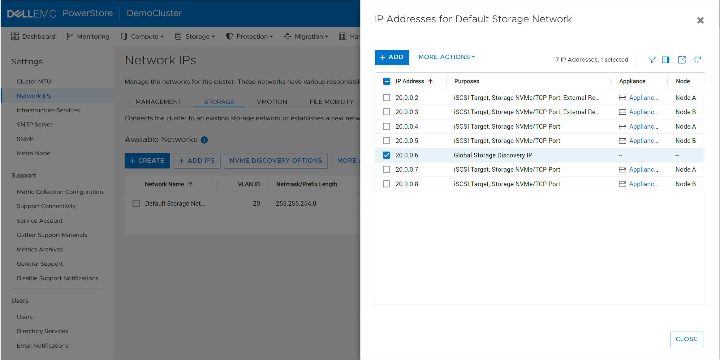
Intelligence
PowerStore includes integrated intelligence that is used to determine the initial placement of a new volume. This is known as the Resource Balancer, which is designed to streamline operations with an integrated machine-learning engine and seamless automation. Resource Balancer works at both the cluster and appliance levels. When a volume is provisioned, the default selection for placement is “Auto.” This setting allows the Resource Balancer to determine the best appliance for the new volume, depending on capacity metrics and configured host access. You can always maintain full control of volume placement by selecting a specific appliance for the volume as well.
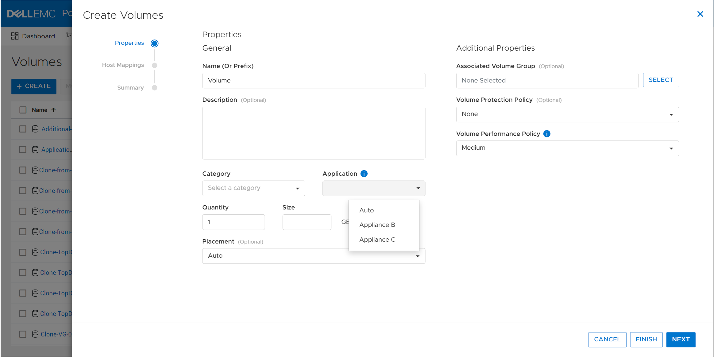
The PowerStore active/active architecture means that volumes can always be accessed through both nodes of an appliance. When a volume is attached to a host, Resource Balancer also selects which node within the appliance to advertise as optimized for host access to that volume. This is known as node affinity. It enables both nodes within the appliance to actively service I/O simultaneously to multiple volumes, so all available hardware is efficiently utilized.
Workload characteristics might evolve over time and cause imbalances between nodes within an appliance. PowerStore features dynamic node affinity, which enables automatic balancing of node affinity of block storage resources between nodes. Dynamic node affinity allows the system to maintain relatively consistent utilization, latency, and performance between both nodes of an appliance. This intelligent architecture enables both seamless load-balancing and high availability.
PowerStore also allows for nondisruptive migration of volumes, volume groups, and vVols across the cluster. As capacity and performance characteristics and requirements change, users can initiate manual or assisted resource migrations of resources from one appliance to another. When resources are migrated, all associated storage objects, such as snapshots and thin clones, are also moved to the same destination.
The system periodically monitors storage resource utilization across all appliances within the cluster. As storage consumption increases over time, an appliance might start to run out of available capacity. In this scenario, the system generates migration recommendations based on factors such as drive wear, appliance capacity, and health. If the administrator accepts the recommendation, a migration session is automatically created. The PowerStore cluster can do all the planning for you!
Flexibility
PowerStore clusters offer flexibility by providing the ability to scale up, out, and down as needed. The initial cluster can be created with anywhere from one to a maximum of four appliances. If the maximum appliance count has not been reached, you can add appliances to the cluster at any time after the initial configuration without any disruption. The additional appliances can be used to add capacity, increase performance, and expand limits.
Within a cluster, you can mix appliances with different configurations such as models, drives, I/O modules, and fault-tolerance levels. NVMe expansion enclosures can be added to specific appliances within the cluster if additional capacity is needed. This allows each appliance in the cluster to have its own individual configuration that’s tailored for its specific use
Administrators can tell PowerStore to evacuate storage resources such as volumes, volume groups, and vVols from an appliance. This operation can be useful in situations where an appliance needs to be powered off for maintenance or removed from a cluster, or when migrating to a new appliance.
Appliances can just as easily be removed from a cluster. For example, after migrating data from one appliance to another, you might want to decommission or repurpose the original appliance. After ensuring that all the data is migrated, the appliance can be safely removed from the cluster. After the appliance is removed, it is reverted to factory settings so it’s ready to be configured as a new cluster, added to an existing cluster, or powered off.
Clustering can be used as an end-to-end life cycle management strategy to make operations such as hardware refreshes painless. The new appliance can be joined to the existing cluster without any impact, enabling both the old and new appliances to be used together. The existing data can be seamlessly and nondisruptively migrated from the old appliance to the new one. The migration can be done either incrementally over time or all at once. Once all the data is migrated, the old appliance can be repurposed or removed from the cluster. All these features and benefits of PowerStore clustering provide you with essential investment protection.
Conclusion
The PowerStore continuously modern storage architecture allows for deploying appliances into a single- or multi-appliance cluster with minimal complexity. PowerStore multi-appliance clusters provide many benefits and advantages, with simplified configuration and administration, integrated intelligence, and increased flexibility.
Resources
Author:
Wei Chen, Senior Principal Engineering Technologist
LinkedIn

Mastering PowerStore
Fri, 03 Feb 2023 23:22:59 -0000
|Read Time: 0 minutes
Introduction
Are you wanting to learn more about PowerStore but not sure where to start? Look no further! In this blog, we describe the top five best PowerStore resources to get you started on PowerStore. These resources include:
- the PowerStore YouTube playlist
- the PowerStore Data Sheet, and
- the Introduction to PowerStore white paper
In this blog we take a look at the advantages of each resource with an emphasis on its use cases and value provided to you.
PowerStore Youtube playlist
The journey towards PowerStore mastery begins at the PowerStore YouTube playlist. The playlist consists of 25 videos and provides an assortment of introduction videos, overviews, demos, lightboard sessions, and discussions of particular features of PowerStore.
To get acquainted with PowerStore at a high level, the introduction videos provide a broad survey of all things PowerStore, including key features, hardware components, architecture, services, performance, and the competitive advantages of PowerStore. These videos leave you wanting to hear more about the technologies and services that PowerStore has to offer.
To understand PowerStore features and services in more detail, the playlist contains another set of overview videos that go over key features and services, such as cybersecurity, hardware, migration, cloud storage services. , and a demo. These videos also include a comprehensive demo that introduces the design of the PowerStore UI.
The videos also include lightboard sessions that have an instruction feel to them. These short-form lightboard sessions go over always-on data reduction, scale up and scale out, machine learning and AI, and PowerStore’s modern software architecture. They do a great job at communicating the technologies that PowerStore has to offer.
Finally, this playlist features discussion videos that further elaborate on VMware virtual volumes, appson, anytime upgrades, and intelligent automation. These take a more personal approach to discussing features and allow the audience to see a back and forth discussion of many questions that viewers may be asking themselves, and to have those questions answered.
PowerStore datasheet
The next resource for mastering PowerStore is the PowerStore Datasheet.
The PowerStore datasheet consolidates PowerStore into four pages and revolves around three key ideas, that PowerStore is:
- adaptable - PowerStore can support any workload, is built for performance, scales up and scales out, and protects critical data.
- intelligent - PowerStore provides self-optimization, proactive health analytics, and programmable infrastructure.
- continuously modern - PowerStore offers an all-inclusive subscription, non-disruptive hardware updates, and an anytime upgrade advantage.
The datasheet also describes the ways you can migrate to PowerStore, and the services that Dell Technologies offers to make the transition to PowerStore as seamless as possible.
A PowerStore white paper: Introduction to the Platform
Building off of the PowerStore datasheet is the white paper Introduction to the Platform.
As the abstract states, this white paper details the value proposition, architecture, and various deployment considerations of the available PowerStore appliances. Where the previous resources discussed (videos and datasheet) provide immediate overviews and discussions to help you grasp PowerStore in a more consolidated way, the Introduction to the Platform white paper takes a deep dive into the details of PowerStore and is intended for IT administrators, storage architects, partners, Dell Technologies employees, and people who are considering PowerStore.
The white paper follows through on your PowerStore education with in-depth displays of the PowerStore value proposition, architecture, and hardware. The hardware section includes information about modules, power supplies, drives, expansion enclosures, and much more. It also includes a glossary of terms and definitions to help you further your understanding of PowerStore and storage as a whole.
Another helpful resource that complements the white paper is the PowerStore Installation and Service guide, available here. This document includes all customer facing hardware procedures, is far more technical, and conveys the level of detail needed to further your knowledge of PowerStore.
PowerStore: Info Hub - Product Documentation & Videos
Hands-on Labs
Sometimes learning is done by doing. This resource does just that! After a proper introduction including videos, datasheet, and in-depth insights, this resource calls you to action. For PowerStore T, the Administration and Management Hands-on Lab and the Data Protection Hands-on Lab walk you through various aspects of PowerStore, and allow you to experience PowerStore’s UX/UI design and its capabilities first hand.
The Administration and Management Hands-on Lab covers three modules:
- PowerStore Management - As the module name states, this module walks you through a wide array of management actions and functions you can perform.This module allows the user to create clusters and manage devices in scale out functions.
- PowerStore Provisioning - This module guides you through step-by-step instructions on how to use the PowerStore Manager UI to provision volumes. PowerStore Manager’s intuitive and easy to use UI design is one of the differentiators that is highlighted in this module.
- PowerStore Monitoring - Finally, the third module walks you through PowerStore monitoring capabilities that include health analytics and warning messages that are delivered to the user.
In the Data Protection Hands-on Lab for PowerStore T, you can walk through various data protection features. There are four modules in this lab:
- PowerStore Protection Policies - allows you to work with PowerStore protection policies, which include scheduled snapshots and replication
- PowerStore Thin Clones - lets you configure and work with thin clones
- PowerStore Import - lets you configure an import session, to PowerStore from another Dell system
- PowerStore Migration – shows how to initiate an internal migration between PowerStore systems in the same cluster
Administration and Management Hands-on Lab
The Dell Technologies Info Hub
The final resource to round out mastering PowerStore is this site itself! The Dell Info Hub contains a wide assortment of blogs regarding particular features, attributes, and releases. From this page, you can find white papers, blogs, and hands-on labs on a variety of PowerStore topics. Whether its block storage, file storage, or updates, the Dell Info Hub provides all sorts of educational materials on all things PowerStore.
https://infohub.delltechnologies.com/t/storage/
Author: Hector Reyes, Analyst, Product Management

Dell PowerStore and Unity XT CSI Drivers Now Available in the Rancher Marketplace
Tue, 31 Jan 2023 17:34:45 -0000
|Read Time: 0 minutes
I am excited to announce that the PowerStore CSI driver and the Unity XT CSI driver are now available in the Rancher Marketplace. Customers have always been able to deploy the CSI drivers on any compatible Kubernetes cluster through a series of manual steps and command lines. If you are using Rancher to manage your Kubernetes clusters, you can now seamlessly deploy the drivers to the managed Kubernetes clusters through the familiar Rancher UI.
Dell CSI drivers
PowerStore CSI driver and Unity XT CSI driver are storage providers for Kubernetes that provide persistent storage for containers. Many containerized workloads, such as databases, often require storing data for a long period of time. The data also needs to follow the containers whenever they move between the Kubernetes nodes. With Dell CSI drivers, database applications can easily request and mount the storage from Dell storage systems as part of the automated workflow. Customers also benefit from the advanced data protection and data reduction features of Dell storage systems.
SUSE Rancher
Rancher is a high-performing open-source Kubernetes management platform. For those who operate and manage multiple Kubernetes clusters across on-premises and in the cloud, Rancher is an attractive solution because of its powerful features that unify the management and security of multiple Kubernetes clusters. Rancher can deploy and manage clusters running on on-premises infrastructure, such as VMware vSphere and on cloud providers such as Azure AKS, Google GKS, and Amazon EKS. Rancher also enhances and simplifies security with centralized user authentication, access control, and observability. The integrated App Catalog provides easy access to third-party applications and simplifies the deployment of complex applications.
The benefits of deploying Dell CSI drivers through the Rancher App Catalog are:
- The App Catalog is based on Helm, a Kubernetes package manager. Dell CSI drivers include the Helm charts in the App Catalog to facilitate the installation and deployment process.
- You can be confident that both Dell and SUSE have validated the deployment process.
- A single management UI to manage all aspects of your Kubernetes clusters.
- Enhances and centralizes user authentication and access control.
- Simplifies the deployment process with fewer command lines and an intuitive HTML5 UI.
- Pre-defined configurations are supplied. You can take the default values or make any necessary adjustments based on your needs.
- Makes it easy to monitor and troubleshoot issues. You can view the status and log files of the cluster components and applications directly in the UI.
How to deploy the CSI driver in Rancher
Let me show you a simple deployment of the CSI driver in Rancher here.
NOTE: Dell CSI drivers are regularly updated for compatibility with the latest Kubernetes version. Keep in mind that the information in this article might change in future releases. To get the latest updates, check the documentation on the Dell Github page (https://dell.github.io/csm-docs/docs).
1. First, review the requirements of the CSI driver. On the Rancher home page, click on a managed cluster. Then, on the left side panel, go to Apps > Charts. In the filter field, enter dell csi to narrow down the results. Click on the CSI driver you want to install. The install page displays the driver’s readme file that describes the overall installation process and the prerequisites for the driver. Perform all necessary prerequisite steps before moving on to the next step.
These prerequisites include, but are not limited to, ensuring that the iSCSI software, NVMe software, and NFS software are available on the target Kubernetes nodes, and that FC zoning is in place.
2. Create a new namespace for the CSI driver in which the driver software will be installed. On the left side panel, go to Cluster > Projects/Namespaces and create a new namespace. Create a csi-powerstore namespace for PowerStore or a unity namespace for Unity XT.
You can optionally define the Container Resource Limit if desired. 
3. The CSI driver requires the array connection and credential information. Create a secret to store this information for the storage systems. On the left side panel, go to Cluster > Storage > Secrets.
For PowerStore:
- Create an Opaque (generic) secret using a key-value pair in the csi-powerstore namespace.
- The secret name must be powerstore-config, with the single key name config. Copy the contents of the secret.yaml file to the value field. A sample secret.yaml file with parameter definitions is available here.
- You can define multiple arrays in the same secret.
For Unity XT:
- Create an Opaque (generic) secret using the key-value pair in the unity namespace.
- The secret name must be unity-creds, with the single key name config. Copy the contents of the secret.yaml file to the value field. A sample secret.yaml file is available here.
- You can define multiple arrays in the same secret.
- The Unity XT CSI driver also requires a certificate secret for Unity XT certificate validation. The secrets are named unity-certs-0, unity-certs-1, and so on. Each secret contains the X509 certificate of the CA that signed the Unisphere SSL certificate, in PEM format. More information is available here.
4. Now, we are ready to install the CSI driver. Go to Apps > Charts and select the CSI driver. Click Install to start the guided installation process.
Select the appropriate namespace (csi-powerstore or unity) for the corresponding driver.
The guided installation also pre-populates the driver configuration in key/value parameters. Review and modify the configuration to suit your requirements. You can find the detailed information about these parameters in the Helm Chart info page (Click the ViewChart Info button on the installation page). (A copy of the values.yaml file that the installation uses is available here for PowerStore and here for Unity XT.)
When the installation starts, you can monitor its progress in Rancher and observe the different resources being created and started. The UI also offers easy access to the resource log files to help troubleshooting issues during the installation.
5. Before using the CSI driver to provision Dell storage, we need to create StorageClasses that define which storage array to use and their attributes. The StorageClasses are used in Persistent Volumes to dynamically provision persistent storage.
To create StorageClasses for Dell storage systems, we use the Import YAML function to create them. If you use the Create function under Storage > StorageClasses, the UI does not offer the Dell storage provisioners in the drop-down menu. Copy and paste the contents of the StorageClass yaml file to the Import Dialog window. (Sample PowerStore StorageClasses yaml files are available here; sample Unity XT StorageClasses yaml files are available here.)
Congratulations! You have now deployed the Dell CSI driver in a Kubernetes Cluster using Rancher and are ready to provision persistent storage for the cluster applications.
Conclusion
Deploying and managing Dell CSI drivers on multiple Kubernetes clusters is made simple with Rancher. Dell storage systems are ideal storage platforms for containers to satisfy the need for flexible, scalable, and highly efficient storage. The powerful features of Rancher streamline the deployment and operation of Kubernetes clusters with unified management and security.
Resources
- https://github.com/dell/csi-powerstore
- https://github.com/dell/csi-unity
- https://dell.github.io/csm-docs/docs/csidriver/installation/
Author: Henry Wong, Senior Principal Engineering Technologist

What’s New in PowerStoreOS 3.2?
Thu, 13 Jul 2023 00:15:24 -0000
|Read Time: 0 minutes
Dell PowerStoreOS 3.2 is the second minor release of 2022 for the Dell PowerStore platform. With this release come some great updates for both PowerStore T and PowerStore X systems as well as enhancements that complement the second generation hardware released in PowerStoreOS 3.0. Check out the full list of features below!
PowerStoreOS 3.2
PowerStoreOS 3.2 includes hardware updates for our 1st generation PowerStore appliances as well as full PowerStore X support.
- Platform: PowerStore 500, 1000, 3000, 5000, 7000, and 9000 T models now support the NVMe Expansion shelves by online upgrade of the Embedded Module (or addition of 4-port card for PowerStore 500).
- Data Mobility: File Mobility Network (used for Async File Replication) can now be deleted and reconfigured while preserving any existing replication sessions.
- PowerStore X: Adds full support of PowerStore X appliances in the PowerStoreOS 3.x code base, adding support for vSphere 7.x. Includes added ESXi licensing alerting and resource information.
- Serviceability: A new data collection profile has been added to help support services get the information they need to troubleshoot faster.
- Scalability: Increased limits of volumes provisioned using NVMe over Fabrics (NVMe/oF).
- Upgrades: Single-hop upgrade from PowerStoreOS 2.1.1 to PowerStoreOS 3.2 to simplify the upgrade process for both PowerStore T and PowerStore X appliances.
Platform
Online upgrade of the embedded module
First generation PowerStore 1000-9000 T appliances can now upgrade their embedded module to support NVMe expansion shelves. The upgrade is performed online non-disruptively. The upgraded embedded module removes the SAS back-end ports and features a new 2-port card that uses 100GbE QSFP ports for back-end connectivity to the NVMe expansion shelves.
Note: Any PowerStore with existing SAS expansion shelves cannot be upgraded because the SAS controller is removed on the new embedded module.
Addition of a 4-port card for PowerStore 500
When purchasing the PowerStore 500, the embedded 4-port card is optional. Without the 4-port card, NAS services, multi-appliance clustering, and NVMe expansion shelves are not supported. In PowerStoreOS 3.2, customers can now add the 4-port card to the appliance online and non-disruptively to an existing system to support the extra functionality that the 4-port card provides.
Addition of 2-port card on PowerStore 1200-9200 T
When purchasing a PowerStore 1200-9200 T model system, the 2-port 100GbE QSFP card used for back-end connectivity is optional and only required when used with NVMe expansion shelves. In PowerStoreOS 3.2, customers can install the 2-port card on existing appliances in an online non-disruptive upgrade procedure and then use the back-end connectivity for adding NVMe expansion shelves.
Data mobility
PowerStoreOS 3.0 introduced the File Mobility Network, which provides management and connectivity for Asynchronous File Replication. To change the mobility network settings of an existing configuration, all file replication sessions would need to be deleted before any changes could be made. In PowerStoreOS 3.2, users can now delete and re-configure the File Mobility Network while keeping all asynchronous file replication sessions intact.
PowerStore X support
Platform
PowerStore X appliances can now be upgraded to PowerStoreOS 3.2. (The previous maximum supported version for PowerStore X was PowerStoreOS 2.1.1.) This means that PowerStore X appliances can now benefit from the feature functionality of PowerStoreOS 3.0 and greater. As part of this upgrade, internal ESXi hosts will be upgraded to ESXi 7.0 Update 3e (build 19898904). For information about the PowerStore 3.0 release, see What’s New In PowerStoreOS 3.0?.
ESXi license alerting
PowerStore X systems now alert the user when the internal ESXi host license is about to expire or has expired. Although this update is relatively small and simple, there is nothing worse than having a licensing issue disrupt your production environment. PowerStore administrators can now notify VMware administrators of any licensing issues or alerts that may occur.
Enhanced resource display in PowerStore Manager
In PowerStore X, the chassis is split into two ESXi nodes, and the PowerStoreOS container resides on a virtual machine within the VMware cluster. The physical resources such as CPU and Memory are split up and allocated: half to the PowerStoreOS container virtual machines that drive the data stack, and half to be used on AppsON virtual machines hosted on the PowerStore appliance. In PowerStoreOS 3.2 we’ve made it easier to see how many resources your virtual machines are consuming verses how many the PowerStoreOS container virtual machines are using.
Scalability
Improved limitations for NVMe over Fabrics (NVMe/oF) volumes. The max number of NVMe/oF volumes are now in line with the max number of SCSI volumes allowed per appliance.
Serviceability
When troubleshooting any type of problem, the last issue you ever want to face is a bottleneck when transferring a data collection bundle up to technical support, especially when time is critical. In PowerStoreOS 3.2, we’ve added a new profile to our data collection script called “minimal”. The “minimal” profile is much smaller in size and will collect only the essential information Dell technical support needs to troubleshoot an issue. From a terminal session as service user, the script can be started using the following command:
$ svc_dc run -p minimal
Upgrading to PowerStoreOS 3.2
With any new operating system upgrade, the next question is “Ok, how do I get there?”. Thankfully, PowerStore supports a simplified and fully non-disruptive upgrade path to PowerStoreOS 3.2.
PowerStore T
PowerStore T model appliances running on 2.0.x or greater can upgrade directly to PowerStoreOS 3.2 with a single-hop upgrade. For all PowerStore upgrades, see the Dell PowerStore Software Upgrade Guide on dell.com/powerstoredocs.
PowerStore X
PowerStore X model appliances running on PowerStoreOS 2.1.1 can upgrade directly to PowerStoreOS 3.2 in a single-hop upgrade. Why not from 2.0.1.3 you ask? Well for PowerStore X, we upgraded our internal ESXi hosts to support vSphere 7 in PowerStoreOS 2.1.1. This is a rather large stepping stone which is why PowerStoreOS 2.1.1 is the minimum version required. To view the current list of vCenter Server versions, see the table “VMware Licensing and Support for PowerStore X” in the PowerStore Simple Support Matrix. Finally, make sure to see the Dell PowerStore Software Upgrade Guide on dell.com/powerstoredocs.
Conclusion
The PowerStoreOS 3.2 release offers NVMe expansion shelf support for our first generation PowerStore models, PowerStore X virtualization integration, file mobility network updates, bug fixes, and more. With the easy non-disruptive upgrade path, this is a great time to upgrade any currently deployed system.
Resources
- What’s New In PowerStoreOS 3.0?
- PowerStore Simple Support Matrix
- Dell PowerStore Software Upgrade Guide
- Dell.com/powerstoredocs
- Dell PowerStore Info Hub
Author: Ryan Meyer, Senior Engineering Technologist

Protect Your Systems and Data with Dell Technologies
Mon, 23 Jan 2023 15:24:08 -0000
|Read Time: 0 minutes
Threats can come from anywhere, which is why it is critical to secure all aspects of your enterprise network — from edge to endpoint, data center to cloud. At Dell Technologies, we make it easier to protect your data wherever it is stored, managed or used with security that’s built into our industry‑leading servers, storage, hyperconverged infrastructure (HCI) and data protection appliances.
Dell PowerStore systems provide a great example of the protection we offer. PowerStore is renowned for helping companies across the globe store and manage data resources. Businesses have come to rely on PowerStore for many reasons, but mainly it’s chosen for its high performance and scale‑out capabilities, versatility, and rich feature set, which delivers all things to all customers. Part of that rich feature set is layer upon layer of security.
Here’s a glimpse into some of the key security features that come with Dell PowerStore systems, and how these features can help to protect your data and system.
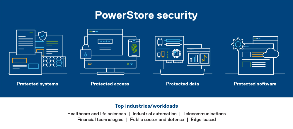
Protected systems
PowerStore includes numerous built-in features designed to protect the system. Features include the hardware root of trust and secure boot, which help to combat rootkit attacks and prevent unwanted code from executing on the OS.
Hardware root of trust provides an immutable, silicon-based solution to cryptographically attest to the integrity of the BIOS and firmware. It ensures that there have been no malicious modifications made throughout the supply chain or after installation.
Likewise, Data at Rest Encryption (D@RE) in PowerStore uses FIPS 140-2 validated self-encrypting drives (SEDs). This capability and KMIP (internal and external key manager support) are critical components of the feature set that help prevent data from being accessed physically, if a drive is removed.
Protected access
We’ve also included access control and logging capabilities with PowerStore to help you manage access to data and systems. Role-based access control and LDAP/LDAPS can reduce employee downtime, improve productivity, and make it easier to set access policies. Audit logging tracks changes and events on the system and can notify you to anomalies.
Dell PowerStore Manager is a critical tool that helps you manage system settings related to security topics, including encryption, and managing SSH access. TLS and IPsec are used to encrypt plaintext communication, protecting sensitive data that PowerStore appliances transmit over the cluster network. HTTP redirect adds another layer of security by redirecting any HTTP request to the more secure HTTPS protocol.
Additional access-related security measures include features like customizable login banners, third-party certificate support, VLAN segmentation, IPv6 support and Secure Connect Gateway.
Protected data
When looking to protect the data that resides on your PowerStore system, you should know that Dell Technologies offers various functionalities to help protect against ransomware and viruses from infecting your system — or to mitigate data loss in unforeseen circumstances.
Read-only snapshots, for example, enable point-in-time restores for data corruption or accidental deletion. PowerStore also allows you to perform asynchronous remote replication to another cluster for localized disasters such as floods or earthquakes. Metro replication lets you replicate synchronously to another cluster at short distances in an active/active configuration. This can help protect against power outages and other natural disasters.
But that’s not all. Other data protection functionality in PowerStore includes things like FLR, CEPA/CAVA for virus and ransomware, Secure NFS (Kerberos), SMB3 data-in-flight encryption, iSCSI CHAP, and Dynamic Resiliency Engine.
Protected software
Finally, to help protect software, Dell Technologies relies heavily on CloudIQ, which is a cloud-based AIOps proactive monitoring and predictive analytics application for Dell systems. CloudIQ uses machine learning and predictive analytics to identify potential issues, anomalies, and security risks, and proactively notifies users, allowing them to take quick action to remediate identified issues. In addition to identifying security risks, the cybersecurity feature in CloudIQ also consolidates security advisories about vulnerabilities in Dell infrastructure products discovered by Dell security specialists and the industry at large.
In addition, our Secure Development Lifecycle Program / Dell maturity model is aligned with NIST guidelines and directives to ensure high standards when it comes to protection. We also offer digitally signed firmware validation, software code integrity, and plug-ins.
Prioritize data protection
Data is the lifeblood of your organization. It’s what makes your business function, which is why you want to take special precautions to protect it.
Dell PowerStore systems make the process of protecting your data easier than ever. Plus, with such a comprehensive feature set to draw from, you’ll find exactly what you need to address your unique security situation and requirements.
Take advantage of the many PowerStore features to protect your data — and the system itself.
Learn more about PowerStore and its security features by checking out these resources:
- Dell PowerStore: Cybersecurity
- Dell PowerStore Manager Overview
- Dell PowerStore: Replication Technologies
- Dell PowerStore: Snapshots and Thin Clones

SQL Server 2022 – Time to Rethink your Backup and Recovery Strategy
Mon, 19 Sep 2022 14:06:43 -0000
|Read Time: 0 minutes
Microsoft SQL Server 2022 is now available in public preview, and it’s jam-packed with great new features. One of the most exciting is the Transact-SQL snapshot backup feature. This is a gem that can transform your backup and recovery strategy and turbocharge your database recoveries!
The power of snapshots
At Dell Technologies we have known the power of storage snapshots for over a decade. Storage snapshots are a fundamental feature in Dell PowerStore and the rest of the Dell storage portfolio. They are a powerful feature that allows point-in-time volume copies to be created and recovered in seconds or less, regardless of size. Since the storage is performing the work, there is no overhead of copying data to another device or location. This metadata operation performed on the storage is not only fast, but it’s space-efficient as well. Instead of storing a full backup copy, only the delta is stored and then coalesced with the base image to form a point-in-time copy.
Starting with SQL Server 2019, SQL Server is also supported on Linux and container platforms such as Kubernetes, in addition to Windows. Kubernetes recognized and embraced the power of storage-based snapshots and provided support a couple of years ago. For managing large datasets in a fast, efficient manner, they are tough to beat.
Lacking full SQL Server support
Unfortunately, prior to SQL Server 2022, there were limitations around how storage-based snapshots could be used for database recovery. Before SQL Server 2022, there was no supported method to apply transaction log backups to these copies without writing custom SQL Server Virtual Device Interface (VDI) code. This limited storage snapshot usage for most customers that use transaction log backups as part of their recovery strategy. Therefore, the most common use cases were repurposing database copies for reporting and test/dev use cases.
In addition, in SQL Server versions earlier than SQL Server 2022, the Volume Shadow Copy Service (VSS) technology used to take these backups is only provided on Windows. Linux and container-based deployments are not supported.
SQL Server 2022 solves the problem!
The Transact-SQL (T-SQL) snapshot backup feature of SQL Server 2022 solves these problems and allows storage snapshots to be a first-class citizen for SQL Server backup and recovery.
There are new options added to T-SQL ALTER DATABASE, BACKUP, and RESTORE commands that allow either a single user database or all user databases to be suspended, allowing the opportunity for storage snapshots to be taken without requiring VSS. Now there is one method that is supported on all SQL Server 2022 platforms.
T-SQL snapshot backups are supported with full recovery scenarios. They can be used as the basis for all common recovery scenarios, such as applying differential and log backups. They can also be used to seed availability groups for fast availability group recovery.
Time to rethink
SQL Server databases can be very large and have stringent recovery time objectives (RTOs) and recovery point objectives (RPOs). PowerStore snapshots can be taken and restored in seconds, where traditional database backup and recovery can take hours. Now that they are fully supported in common recovery scenarios, T-SQL snapshot backup and PowerStore snapshots can be used as a first line of defense in performing database recovery and accelerating the process from hours to seconds. For Dell storage customers, many of the Dell storage products you own support this capability today since there is no VSS provider or storage driver required. Backup and recovery operations can be completely automated using Dell storage command line utilities and REST API integration.
For example, the Dell PowerStore CLI utility (PSTCLI) allows powerful scripting of PowerStore storage operations such as snapshot backup and recovery.
Storage-based snapshots are not meant to replace all traditional database backups. Off-appliance and/or offsite backups are still a best practice for full data protection. However, most backup and restore activities do not require off-appliance or offsite backups, and this is where time and space efficiencies come in. Storage-based snapshots accelerate the majority of backup and recovery scenarios without affecting traditional database backups.
A quick PowerStore example
Backup
The overall workflow for a T-SQL snapshot backup is:
- Issue the T-SQL ALTER DATABASE command to suspend the database:
ALTER DATABASE SnapTest SET SUSPEND_FOR_SNAPSHOT_BACKUP = ON - Perform storage snapshot operations. For PowerStore, this is a single command:
pstcli -d MyPowerStoreMgmtAddress -u UserName -p Password volume_group -name SQLDemo -name SnapTest-Snapshot-2208290922 -description “s:\sql\SnapTest_SQLBackupFull.bkm” - Issue the T-SQL command BACKUP DATABASE command with the METADATA_ONLY option to record the metadata and resume the database:
BACKUP DATABASE SnapTest TO DISK = 's:\sql\SnapTest_SQLBackupFull.bkm' WITH METADATA_ONLY,COPY_ONLY,NOFORMAT,MEDIANAME='Dell PowerStore PS-13',MEDIADESCRIPTION='volume group: SQLDemo',NAME='SnapTest-Snapshot-2208290922',DESCRIPTION=' f85f5a13-d820-4e56-9b9c-a3668d3d7e5e ' ;
Since Microsoft has fully documented the SQL Server backup and restore operations, let’s focus on step 2 above, the PowerStore CLI command. It is important to understand that when taking a PowerStore storage snapshot, the snapshot is being taken at the volume level. Therefore, all volumes that contain data and log files for your database require a consistent point-in-time snapshot. It is a SQL Server Best Practice for PowerStore to place associated SQL Server data and log volumes into a PowerStore volume group. This allows for simplified protection and consistency across all volumes in the volume group. In the PSTCLI command above, a PowerStore snapshot is taken on a volume group containing all the volumes for the database at once.
Also, a couple of tips for making the process a bit easier. The PowerStore snapshot and the backup metadata file need to be used as a set. The proper version is required for each because the metadata file contains information such as SQL Server log sequence numbers (LSNs) that need to match the database files. Therefore, I’m using several fields in the PowerStore and SQL Server snapshot commands to store information on how to tie this information together:
- When the PowerStore snapshot is taken in step 2 above, in the name field I store the database name and the datetime that the snapshot was taken. I store the path to the SQL Server metadata file in the description field.
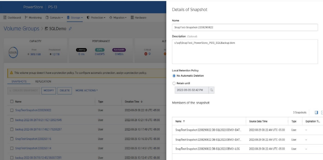
- In step 3, within the BACKUP DATABASE command, I put the PowerStore friendly name in the MEDIANAME field, the PowerStore volume group name in the NAME field, and the PowerStore volume group ID in the DESCRIPTION field. This populates the metadata file with the necessary information to locate the PowerStore snapshot on the PowerStore appliance.
- The T-SQL command RESTORE HEADERONLY will display the information added to the BACKUP DATABASE command as well as the SQL Server name and database name.
Recovery
The overall workflow for a basic recovery is:
- Drop the existing database.
- Offline the database volumes. This can be done through PowerShell, as follows, where X is the drive letter of the volume to take offline:
Set-Disk (Get-Partition -DriveLetter X | Get-Disk | Select number -ExpandProperty number) -isOffline $true - Restore the database snapshot using PowerStore PSTCLI:
- List volume groups.
pstcli -d MyPowerStoreMgmtAddress -u UserName -p Password! volume_group show - Restore the volume group where f85f5a13-d820-4e56-9b9c-a3668d3d7e5e is a volume group ID from above.
pstcli -d MyPowerStoreMgmtAddress -u UserName -p Password! volume_group -name SQLServerVolumeGroup restore -from_snap_id f85f5a13-d820-4e56-9b9c-a3668d3d7e5e
- List volume groups.
- Online the database volumes. The following PowerShell command will online all offline disks:
Get-Disk | Where-Object IsOffline -Eq $True | Select Number | Set-Disk -isOffline $False - Issue the T-SQL RESTORE DATABASE command referencing the backup metadata file, using the NORECOVERY option if applying log backups:
RESTORE DATABASE SnapTest FROM DISK = 's:\sql\SnapTest_PowerStore_PS13_SQLBackup.bkm' WITH FILE=1,METADATA_ONLY,NORECOVERY - If applicable, apply database log backups:
RESTORE LOG SnapTest FROM DISK = 's:\sql\SnapTest20220829031756.trn' WITH RECOVERY
Other items of note
A couple of other items worth discussing are COPY_ONLY and differential backups. You might have noticed above that the BACKUP DATABASE command contains the COPY_ONLY parameter, which means that these backups won’t interfere with another backup and recovery process that you might have in place.
It also means that you can’t apply differential backups to these T-SQL snapshot backups. I’m not sure why one would want to do that; I would just take another T-SQL snapshot backup with PowerStore at the same time, use that for the recovery base, and expedite the process! I’m sure there are valid reasons for wanting to do that, and, if so, you don’t need to use the COPY_ONLY option. Just be aware that you might be affecting other backup and restore operations, so be sure to do your homework first!
Stay tuned
There will be a lot more information and examples coming from Dell Technologies on how to integrate this new T-SQL snapshot backup feature with Linux and Kubernetes on PowerStore as well as on other Dell storage platforms. Also, look for the Dell Technologies sessions at PASS Data Community Summit 2022, where we will have more information on this and other exciting new Microsoft SQL Server 2022 features!
Author: Doug Bernhardt
Sr. Principal Engineering Technologist
https://www.linkedin.com/in/doug-bernhardt-data/

Provision PowerStore Metro Volumes with Dell Virtual Storage Integrator (VSI)
Tue, 30 Aug 2022 19:55:24 -0000
|Read Time: 0 minutes
Since PowerStoreOS 3.0, native metro volumes have been supported for PowerStore in vSphere Metro Storage Cluster configurations. With the new Virtual Storage Integrator (VSI) 10.0 plug-in for vSphere, you can configure PowerStore metro volumes from vCenter without a single click in PowerStore Manager.
This blog provides a quick overview of how to deploy Dell VSI and how to configure a metro volume with the VSI plug-in in vCenter.
Components of VSI
VSI consists of two components—a VM and a plug-in for vCenter that is deployed when VSI is registered for the vCenter. The VSI 10.0 OVA template is available on Dell Support and is supported with vSphere 6.7 U2 (and later) through 7.0.x for deployments with an embedded PSC.
Deployment
A deployed VSI VM requires 3.7 GB (thin) or 16 GB (thick) space on a datastore and is deployed with 4 vCPUs and 16 GB RAM. The VSI VM must be deployed on a network with access to the vCenter server and PowerStore clusters. During OVA deployment, the import wizard requests information about the network and an IP address for the VM.

When the VM is deployed and started, you can access the plug-in management with https://<VSI-IP>.
Register VSI plug-in in vCenter
A wizard helps you register the plug-in in a vCenter. Registration only requires that you set the VSI Redis Password for the internal database and username/password.

After the VSI VM is configured, it takes some time for the plug-in to appear in vCenter. You might be required to perform a fresh login to the vSphere Client before the Dell VSI entry appears in the navigation pane.
From the Dell VSI dashboard, use the + sign to add both PowerStore clusters used for metro volumes.
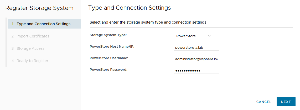
Configure a metro volume with the VSI plug-in
As with PowerStore Manager, creating a metro volume with the VSI plug-in requires three steps:
- Create and map a standard volume.
- Configure metro for the newly created volume.
- Map the second metro volume to the hosts.
The following example adds a new metro volume to cluster Non-Uniform, which already has existing metro volumes provisioned in a Non-Uniform host configuration. Esx-a.lab is local to PowerStore-A, and esx-b.lab is local to PowerStore-B.
- Create and map a standard volume in vSphere.
Use the Actions menu either for a single host, a cluster, or even the whole data center in vSphere. In this example, we chose Dell VSI > Create Datastore for the existing cluster Non-Uniform. - Configure metro for the newly created volume.
The VSI Create Datastore wizard leads us through the configuration.- For a metro volume, select the volume type VMFS.
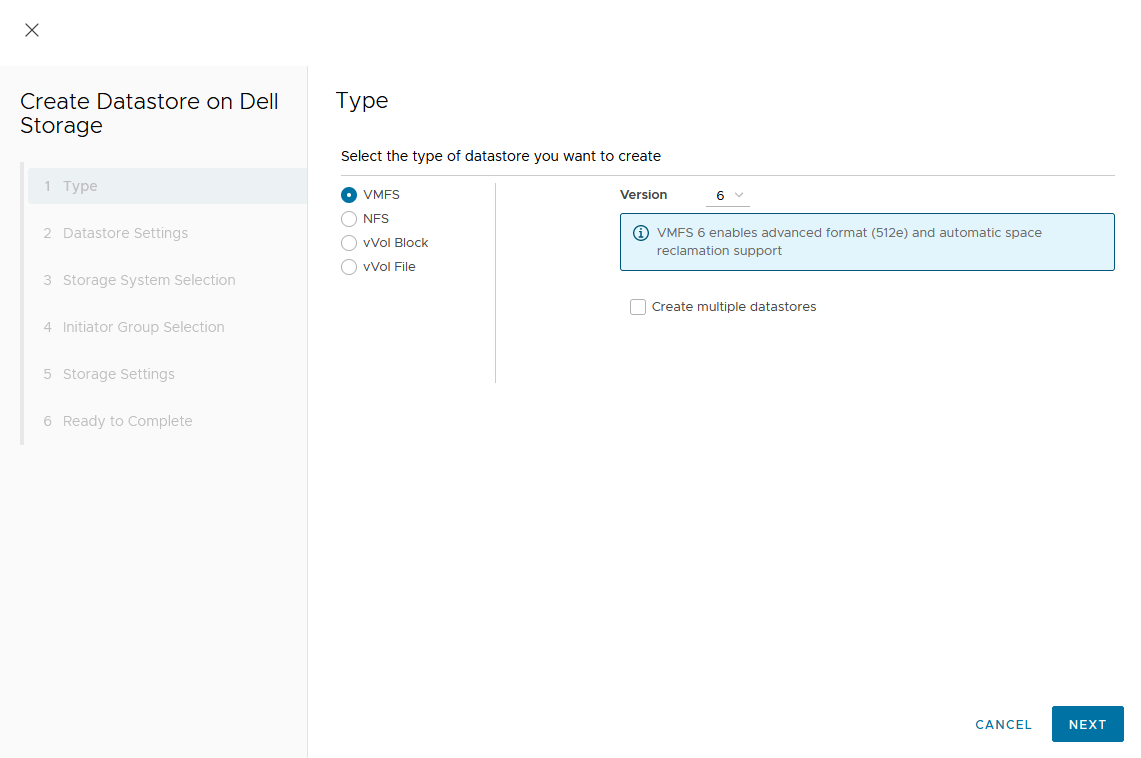
- Provide a name for the new volume.
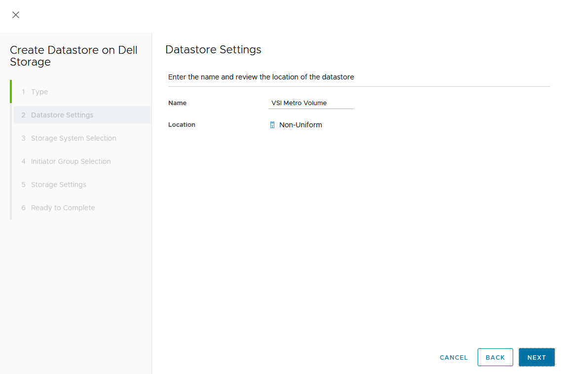
- Select the storage system.
- For a metro volume, select the volume type VMFS.
In the dialog box, you can expand the individual storage system for more information. We start with PowerStore-A for esx-a.lab.
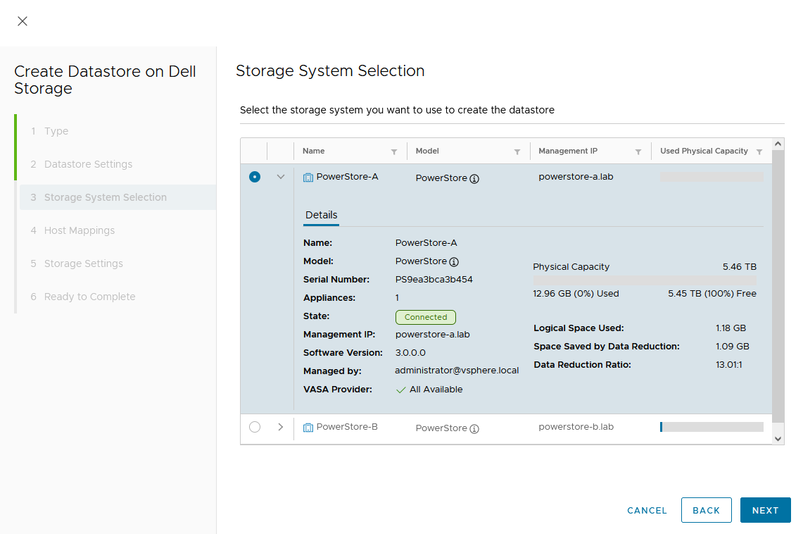
d. Map the host.
As this is a Non-Uniform cluster configuration, only esx-a.lab is local to PowerStore-A and should be mapped to the new volume on PowerStore-A.
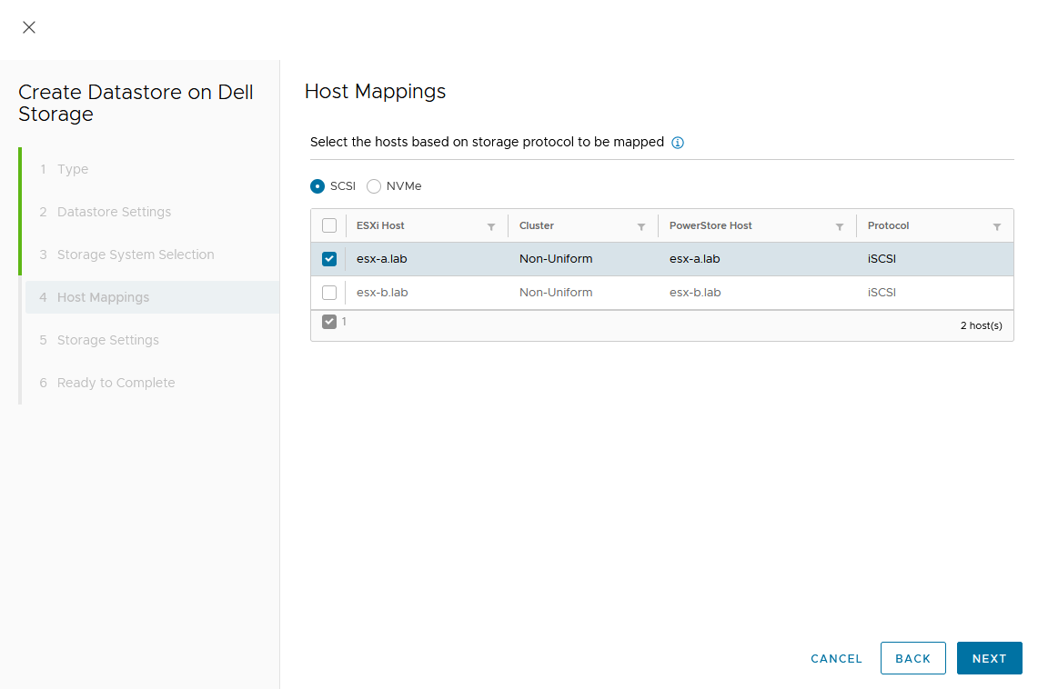
e. Set a Capacity and select other volume settings such as Performance Policy or Protection Policy.
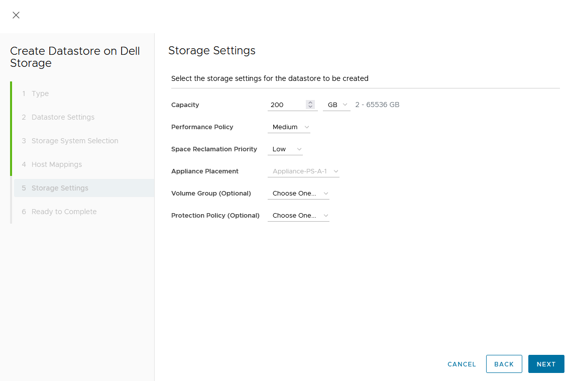
Wizard summary page:
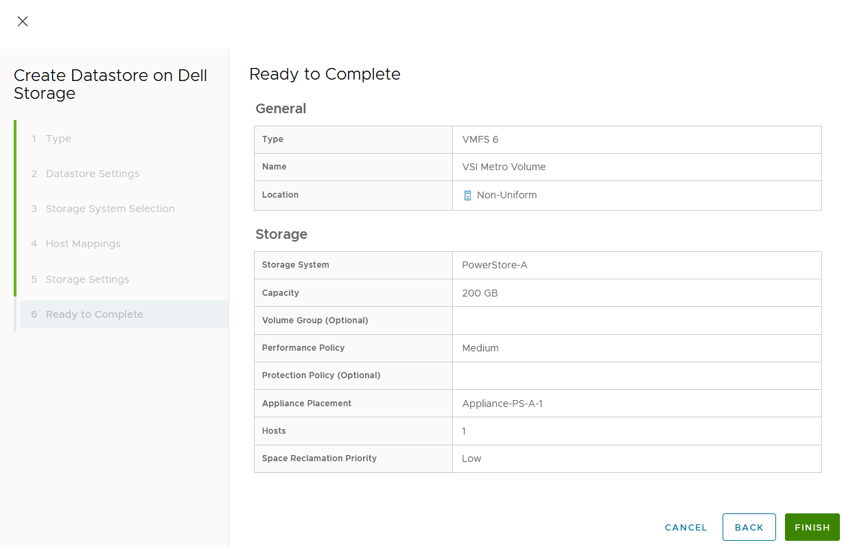
Upon completion, the volume is configured and mapped to the host. The following screenshot shows the new volume, VSI Metro Volume, and the tasks that ran to create and map the volume in vSphere.
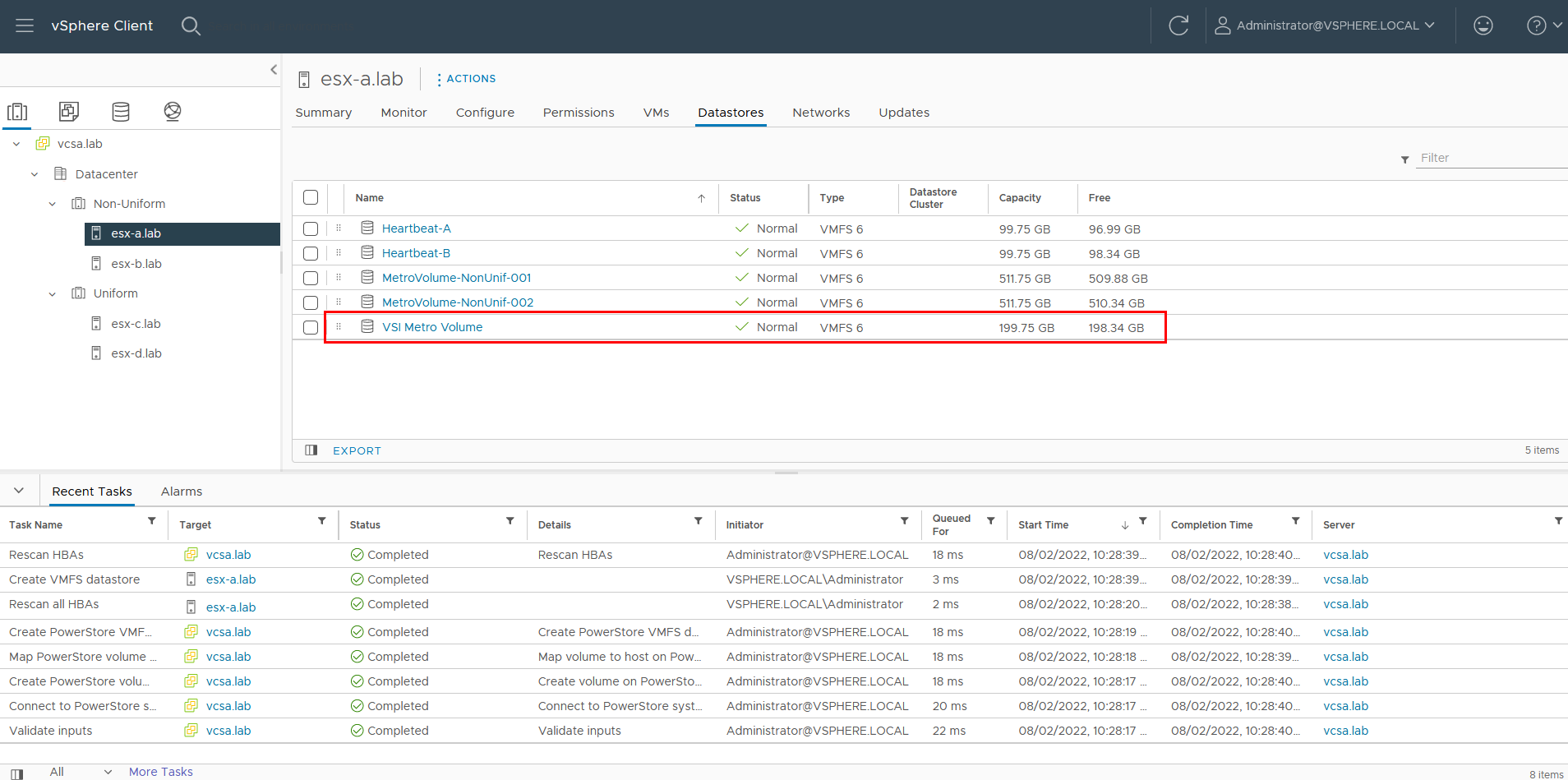
For reference, the related jobs in PowerStore Manager for PowerStore-A are also available at Monitoring > Jobs:
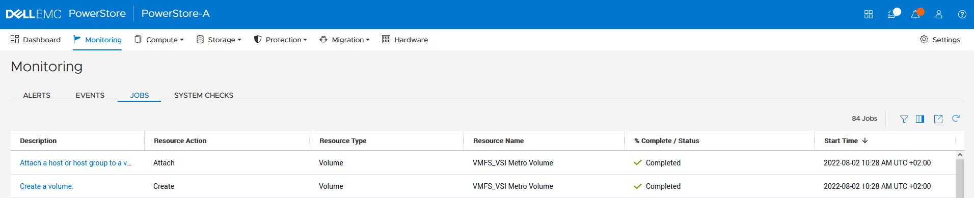
f. Select the VSI Metro Volume datastore, and then select Configure > Dell VSI > Storage to see the details for the backing device.
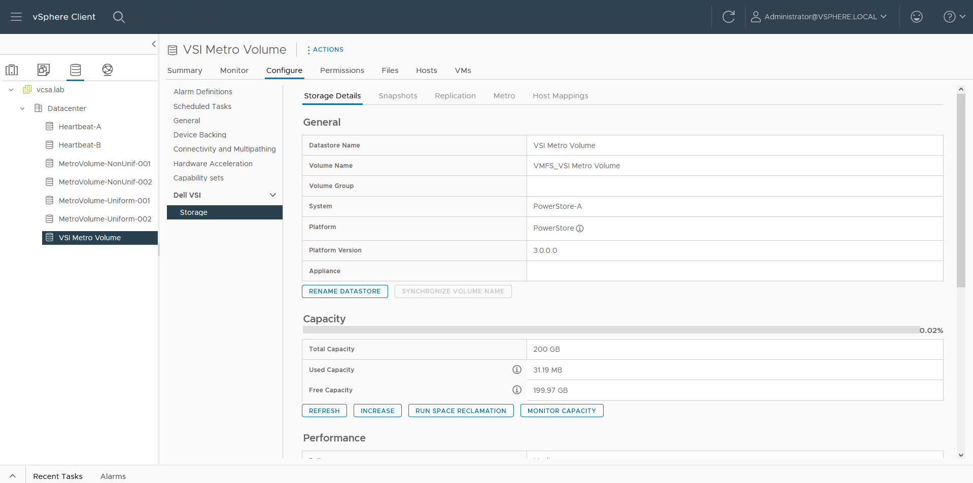
g. On the Storage Details tab under Protection, click Configure Metro.
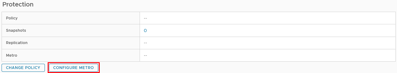
h. In the Configure Metro Volume dialog box, specify the Remote System and whether host mapping should be performed.
Depending on host registrations on PowerStore, automatic mapping may be unwanted and can be skipped. In this example, PowerStore-B has also the esx-a.lab host registered to provide access to one of the heartbeat volumes required for vSphere HA. The host mapping operation in the Create Datastore wizard creates an unwanted mapping of the volume from PowerStore-B to esx-a.lab. To configure manual mapping after the metro volume is created, select Do not perform the host mapping operation.
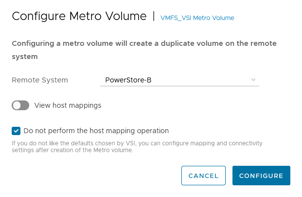
The metro volume is immediately configured on PowerStore and the Metro tab in Dell VSI > Storage view shows the status for the metro configuration.
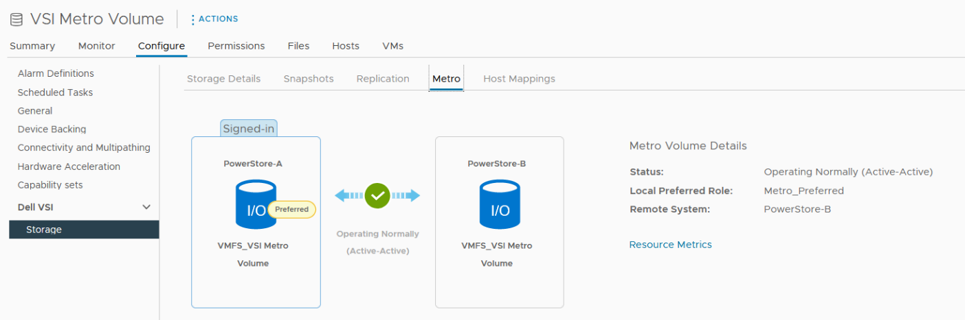
3. Map the second metro volume to the host.
Because we skipped host mapping when we created the metro volume, we must map the esx-b.lab host to the metro volume on PowerStore-B on the Host Mappings tab. Currently, the volume is only mapped from PowerStore-A to esx-a.lab.
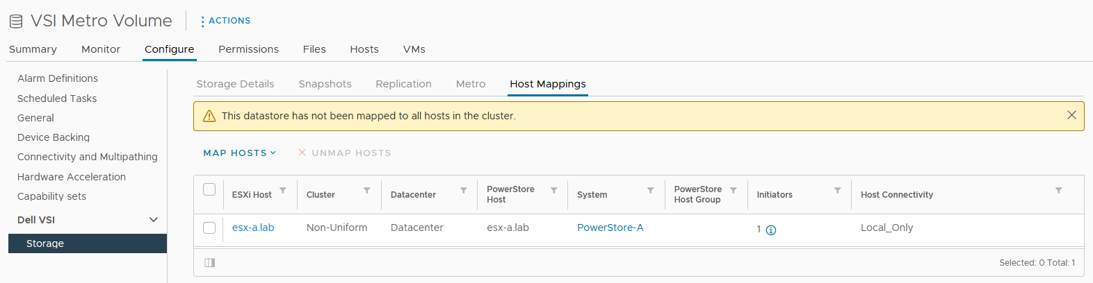
a. Select Map Hosts > PowerStore-B to open the Map Hosts dialog box.
b. Map the volume on PowerStore-B for esx-b.lab.
The host mapping overview shows the result and concludes the metro volume configuration with Virtual Storage Integrator (VSI) plugin.
Resources
- Dell Virtual Storage Integrator (VSI) for VMware vSphere Client Version 10.0 Product Guide
- Dell PowerStore Protecting Your Data—Metro Protection
- Dell PowerStore: Metro Volume
Author: Robert Weilhammer, Principal Engineering Technologist
https://www.xing.com/profile/Robert_Weilhammer

Guide for Configuring PowerStore with an SSL Certificate
Tue, 30 Aug 2022 14:11:47 -0000
|Read Time: 0 minutes
SSL certificates are commonly used when browsing the internet. Even corporate intranet pages are usually protected with an encrypted SSL connection. The two major security improvements when using SSL certificates are:
- Authenticity to prove a trusted server
- Encryption to protect (sensitive) data
Let’s start with some quick basics. I guess everyone has seen the nice error message about expired or invalid certificates in a browser. Some browsers even don’t allow you to continue when hitting a page with an expired certificate.
When Dell PowerStore is installed, it internally generates a self-signed certificate to allow data encryption between browser and PowerStore. Because the signed certificate is not trusted by the browser, a warning indicates that the page is not trusted. To mitigate the warning, PowerStoreOS allows the administrator to change the out-of-the box self-signed certificate with a trusted SSL certificate, ideally signed by a trusted certification authority (CA).
Besides the major commercial and public CAs, some companies run their own company-wide certificate authority. A private CA is usually part of a Private Key Infrastructure (PKI) and can provide certificates for different purposes. To allow the browser to validate certificates, the certificate of the private CA needs to be installed as a trusted Certificate Authority in the browser.
A certificate always consists of at least two parts:
- A secret key which is used to sign other certificates or to encrypt data
- A public key which is included in a certificate
When a certificate or data is signed or encrypted with a private key, the public shared key can be used to decrypt the information. Fingerprints within the certificate file help verify whether the shared key and decrypted information can be trusted.
The structure of trusted certificates is always hierarchical and based on a Root CA certificate, which is at the top of the trust chain. A Root CA can have one or more Intermediate CAs, which are usually used to sign a server certificate by a certificate authority. In the same way when a client requests data from an SSL protected site, the server uses the certificate key to sign and encrypt the data and sends the response with the public certificate to the client. The client uses the response to check and validate the certificate attributes. These important attributes are the “valid from” and “valid to” timestamps, whether the URL matches the subject of the certificate, and whether the certificate is signed by a trusted CA certificate in the client certificate store. The check against a trusted CA certificate proves the authenticity. When all checks are passed, the browser indicates that the page can be trusted.
SSL certificates involve some different files:
Certificate | Description |
Certificate “key” file | Contains the key to encrypt and sign data. The key file should be kept safe. |
Certificate Sign Request (CSR) | The certificate sign request is generated with information from the key file and contains the information for a CA to issue a certificate file. Included information for a CSR generated with PowerStore: Subject: Concatenated string containing Organization, Organizational Unit, Location, State, and Common Name as given in PowerStore Manager when creating the CSR. SAN: A X509v2 extension called “Subject Alternate Names” which is the DNS and IP information as entered Public-Key: The public part of the private key file |
Certificate file | This could be either a single certificate or a certificate chain. A certificate chain is a set of concatenated certificates that allows clients to validate a certificate down to a trusted (CA) certificate. There are different file formats possible: PEM: “Privacy-Enhanced Mail” is commonly used to exchange certificates DER: “Distinguished Encoding Rules” is a binary encoding for PEM files PFX/PKCS: Another type called personal information exchange format When dealing with SSL certificates for Dell PowerStore, the PEM format is used. |
CA Certificate / | This is the public certificate of the issuer CA of a certificate. A PowerStore does not know anything of the issuer and needs the CA certificate to build the whole chain of trust for the certificate. Sometimes the file includes the whole certificate chain that consists of concatenated PEM certificates CA -> [Intermediate CA] -> PowerStore The included certificates in a chain depend on the issuer of a certificate. For PowerStore, we require the chain of certificates in following order:
|
Since PowerStoreOS 2.0, it’s possible to install 3rd party / signed server certificates for PowerStore T models in a block only deployment using PowerStore REST API or PowerStore CLI. PowerStoreOS 3.0 adds support for PowerStore T unified deployments and a GUI in PowerStore Manager for SSL import. This provides a comfortable way to generate a certificate sign request (CSR) and install the certificate. The certificate key file is stored in PowerStore and cannot be exported.
The next sections describe how to use PowerStore Manager and the PowerStore CLI to install a third party SSL certificate.
Installing a third party SSL certificate (PowerStore Manager)
The following figure illustrates the steps required to deploy the certificate in PowerStore Manager:
- Log into PowerStore Manager.
Note that your browser shows that the connection is not secure: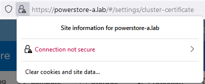
- Go to PowerStore Settings > Security > Signed Cluster Certificate.
- Click the Generate CSR button and enter the required information to request a certificate.
a. Common Name Name of the certificate – usually the PowerStore cluster name
b. Cluster and ICM IP Mandatory for the Certificate and can’t be changed
c. IP Addresses Alternate IP Addresses which should appear in the certificate.
d. DNS name PowerStore FQDN
e. Organization Company Name
f. Organizational Unit Team / Organization
g. Locality Town
h. State State
i. Country/Region Two-letter country code
j. Key Length 2048 or 4096
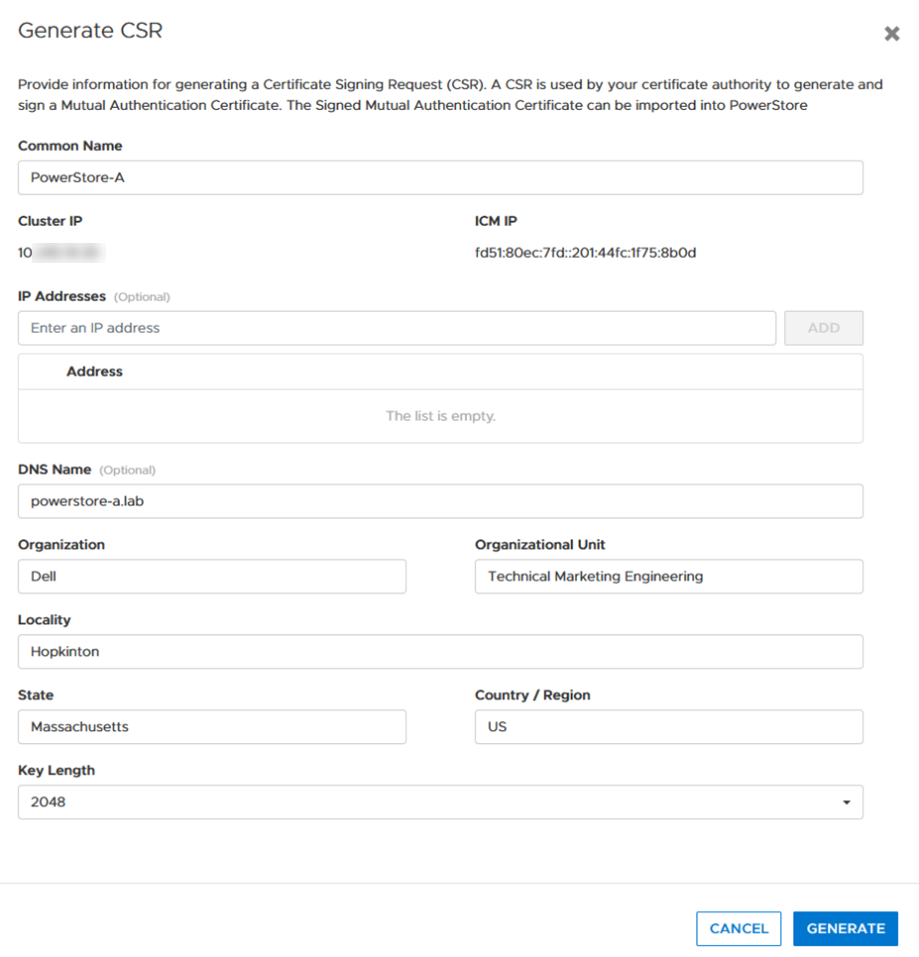
4. When the CSR is created, click copy to clipboard and export the CSR content to a file -> for example, PowerStore.CSR
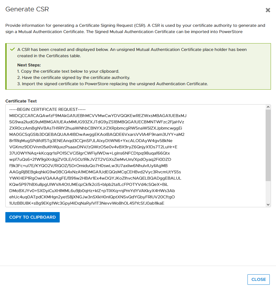
Optional: you can use the openssl tool to extract the contents of the CSR in a human readable format:
# openssl req -noout -text -in PowerStore.CSR
5. Send the CSR to your Certification Authority / PKI.
When there is an option to specify the format of the response, choose “PEM” format for the PowerStore and CA certificate. These files can be easily concatenated to a single certificate chain file (using the Linux CLI or a text editor) for import:
# cat powerstore.crt CA.crt > chain.crt
6. If not completed already, import the CA Certificate into your browser.
7. In PowerStore Manager, import the certificate chain in same screen where the CSR was generated.
Important: Sometimes the certificate file is in blocks. PowerStore expects the certificate in single lines, as in the following example with a PowerStore- and CA certificate:
-----BEGIN CERTIFICATE-----
[...Single line PowerStore certificate content...]
-----END CERTIFICATE-----
-----BEGIN CERTIFICATE-----
[...Single line CA Certificate certificate content...]
 -----END CERTIFICATE-----
If the individual certificates are not on a single line, the import will fail with the error “Failed to update certificate in credential store. Please verify your certificate chain. (0xE09010010013)”. You can use the openssl tool to verify that the file is ok:
# openssl x509 -in powerstore-chain.crt -noout -text
8. Start using PowerStore with a trusted HTTPS connection.
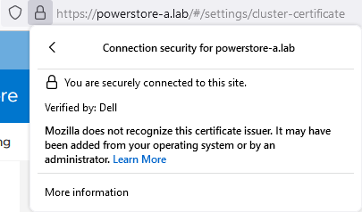
Installing a third party SSL certificate (PowerStore CLI)
Follow these steps to generate a certificate with PowerStore CLI for PowerStore-A. Be sure to format the CSR and certificate file correctly.
1. Generate CSR:
cli> x509_certificate csr -type Server -service Management_HTTP -scope External -key_length 2048 -common_name PowerStore-A -dns_name powerstore-a.lab -organizational_unit "Technical Marketing Engineering" -organization Dell -locality Hopkinton -state Massachusetts -country US
The response shows an ID and the CSR in a block. Keep the ID noted somewhere as it will be required for import. Also, use a text editor to make sure BEGIN- and END CERTIFICATE REQUEST are each on their own line when requesting the certificate:
-----BEGIN CERTIFICATE REQUEST-----
[... a nice formatted block or single line ...]
 -----END CERTIFICATE REQUEST-----
2. Use CSR content to request the certificate.
3. Ensure that the issued certificate file is a single line string as required for import in PowerStore Manager. Note that the required line breaks need to be “\n”.
4. Import the certificate by using the ID and the certificate string:
cli> x509_certificate -id f842d778-0b28-4012-b8d5-66ead64d38e4 set -is_current yes -certificate “-----BEGIN CERTIFICATE-----\n[...Single line PowerStore certificate content...]\n-----END CERTIFICATE-----\n-----BEGIN CERTIFICATE-----\n[...Single line CA Certificate certificate content...] \n-----END CERTIFICATE-----"
Terms used:
CA Certification Authority
CN Common Name
CSR Certificate Sign Request
chain Single “chain” file with concatenated certificates
key Private certificate key
PEM Privacy-Enhanced Mail and commonly used to exchange certificates
SAN Subject Alternate Name
Resources
Author: Robert Weilhammer, Principal Engineering Technologist

Let’s Talk File (#5) – NFS Protocol Overview
Tue, 23 Aug 2022 16:05:07 -0000
|Read Time: 0 minutes
Introduction
A file access protocol enables clients and storage systems to transmit data using a common syntax and defined rules. PowerStore file supports a wide range of protocols including SMB, NFS, FTP, and SFTP.
In our last blog, we discussed a commonly used protocol for file sharing called Server Message Block (SMB). In this blog, we’ll review another commonly used protocol for file sharing called Network File System (NFS). NFS is commonly used for use cases such as departmental shares, databases, VMware NFS datastores, and more.
NFS versions
PowerStore supports NFSv3 through NFSv4.1. NFSv3 is a stateless protocol that includes basic security, requires external locking mechanisms, and UNIX-based mode bits for permissions. NFSv4 is a stateful protocol that enables enhanced security, integrated locking, ACLs for permissions, and adds other enhancements.
In addition, Secure NFS is also supported. Traditionally, NFS is not the most secure protocol, because it trusts the client to authenticate users and build user credentials and send these in clear text over the network. With the introduction of Secure NFS, Kerberos can be used to secure data transmissions through user authentication and data signing through encryption. Kerberos is a well-known strong authentication protocol where a single key distribution center, or KDC, is trusted rather than each individual client. There are three different Secure NFS modes available on PowerStore:
- Kerberos: Use Kerberos for authentication only
- Kerberos With Integrity: Use Kerberos for authentication and include a hash to ensure data integrity
- Kerberos With Encryption: Use Kerberos for authentication, include a hash, and encrypt the data in-flight
NFS configuration
To configure NFS, you must first enable NFS on the NAS server, create a file system, and an NFS export.
The first step to configure an NFS environment is to provision a NAS server. Each NAS server has options to enable NFSv3 and NFSv4 independently. The following figure shows the NFS protocol options in the NAS server provisioning wizard. 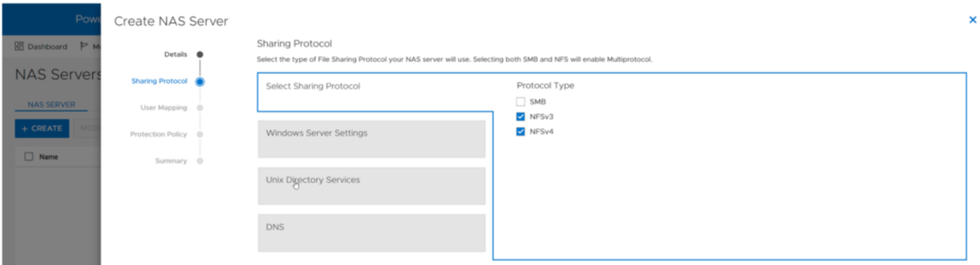
If at least one NFS protocol is enabled, you are then presented with the option to enable a UNIX Directory Service (UDS). The purpose of the UDS is to provide a mechanism to resolve names to IDs and vice versa. This is necessary because the file system tracks users and files using user IDs and group IDs (UIDs and GIDs). These IDs can be resolved to usernames and group names, and these names are displayed to improve usability for humans. The available options for the UDS are:
- Local Files - Individual files that are uploaded to the NAS server to provide name and ID resolution
- Ideal for small or isolated environments
- Quick and easy to configure
- Do not scale well because files need to be uploaded to each NAS server if anything changes
- These share the same syntax as the configuration files that are found in the /etc/ directory on a UNIX host
- A copy of a local file from a host can be re-purposed for the NAS server
- PowerStore also provides a template with the syntax and descriptions
- NIS/LDAP - Services that provide a centralized user directory for name and ID resolution
- Ideal for large environments that require consistent UID/GID mappings across multiple NAS servers
- Requires upfront work for initial deployment
- Scales well and updates can be easily propagated
In addition to the UDS, Secure NFS can also be enabled at this step. All options in this step are optional and can be skipped if they are not required in your environment. The following figure shows the UNIX Directory Services step of the NAS server provisioning wizard.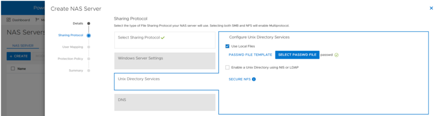
When the UDS is configured, the final step in the wizard prompts you to enable DNS for IP address and name resolution. This step is also optional and can be skipped if DNS is not required in your environment.
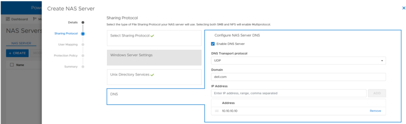
Any of the settings that are set during the initial provisioning of the NAS server can also be changed afterwards.
NFS exports
When the NFS-enabled NAS server is configured, you can provision a file system along with a NFS export. The NFS export provides a path that clients can use to mount the file system. The initial NFS export can optionally be created as part of the file system provisioning wizard. Additional NFS exports can also be created on existing file systems, if the path exists.
In the NFS export step of the file system provisioning wizard, the only required field is the name for the export. You can also see the name of the NAS Server, local path, file system name, and NFS export path on the right, as shown in the following figure.
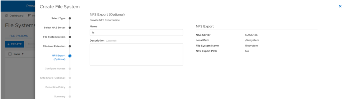
You can re-use the local path as the name of the export or provide a different name. If the provided name is different from the local path, then the name is used to create an NFS alias. An NFS alias is another path that can be used to mount the export that is different from the actual path to the share. For example, if the name is fs and the local path is /filesystem, both can be used to mount the export even though the actual path to the export is /filesystem. After the export is created, you can also see that both paths are valid when running the showmount command to the NAS server interface, as shown in the following figure.
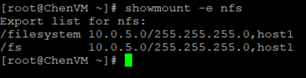
The next step in the wizard allows you to configure the access permissions to the NFS export. The following options are available:
- Minimum Security – The minimum authentication method allowed to access the NFS export. The Kerberos options are only available if Secure NFS is enabled.
- Sys (Default) – User authenticates when logging on to the client, so the client passes the user’s IDs to the NFS server without needing to authenticate directly
- Kerberos – Use Kerberos for authentication only
- Kerberos With Integrity – Use Kerberos for authentication and include a hash to ensure data integrity
- Kerberos With Encryption – Use Kerberos for authentication, include a hash, and encrypt the data in-flight
- Default Access – Determines the access permissions for all hosts that attempt to connect to the NFS export. The available options are:
- No Access (Default)
- Read/Write
- Read-Only
- Read/Write, allow Root
- Read-Only, allow Root
Note: The allow root options are the equivalent to no_root_squash on UNIX systems. This means if the user has root access on the client, they are also granted root access to the NFS export. Allow root is required for some use cases, such as VMware NFS datastores.
- Override List - Hosts that need different access than the default can be configured by adding hostnames, IP addresses, or subnets to the override list with one of the access options listed above.
- Comma-Separated - Multiple entries can also be added simultaneously in a comma-separated format. The following table shows the supported options when configuring NFS host access:
Name | Examples | Notes |
Hostname | host1.dell.com | Hostname should be defined in the local hosts file, NIS, LDAP, or DNS |
IPv4 or IPv6 Address | 10.10.10.10 fd00:c6:a8:1::1 |
|
Subnet | 10.10.10.0/255.255.255.0 | IP address/netmask or IP address/prefix |
- CSV File - Host access can also be configured by uploading a CSV file with a list of hosts and their respective access levels.
- PowerStore Manager provides a template with examples of the formatting and syntax for this file. This template can be downloaded from the system, edited, and then imported.
- When multiple NFS exports that require the same access configuration are configured, the same file can be imported multiple times and across multiple clusters as well.
- When the file is imported, the newly imported hosts are appended to the access list.
The following figure shows the host access configuration on an NFS export.
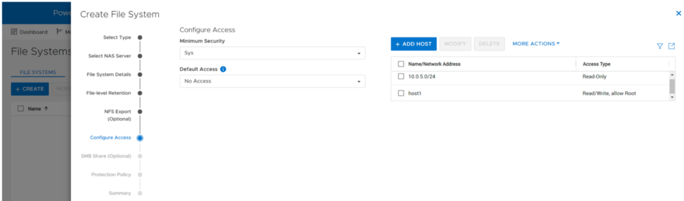
Mounting an NFS export
When you have created the NFS export, you can mount the NFS export on a client that is configured for access. If you attempt to mount the NFS export from a client that has no access, an access denied error is returned. If you attempt to mount a path that is not a valid NFS export, you will also see an access denied error.
To mount the NFS export, use the mount command. The syntax is:
mount <NFS_Server_Interface>:/<Path_or_Alias> /<Mountpoint>.
For example, mount nfs:/fs /mnt/nfs connects to the interface with the DNS name of nfs, looks for the /fs path or alias, and then mounts it to the /mnt/nfs/ directory on the client.
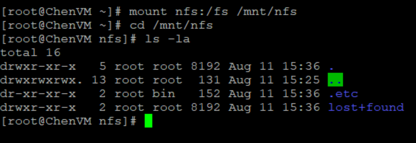
Depending on the client OS version, the default mount option may vary between NFSv3 and NFSv4. If both are enabled on the NAS server and you want to use a specific version, you should specify it using the -t switch in the mount command.
To confirm that the NFS export is mounted and see the mount options, use the mount command, as shown in the following figure.
When it is mounted, you can simply change directory (cd) into /mnt/nfs to access the data on the NFS export.
Conclusion
Great job! You are now familiar with how to use the NFS protocol for file system access. This enables you to start configuring environments using NFS for many use cases and applications. Stay tuned for the next blog in this series where we’ll review how we can hide the .etc and lost+found directories from the end user.
Resources
Author: Wei Chen, Senior Principal Engineering Technologist

Hybrid Kubernetes Clusters with PowerStore CSI
Mon, 25 Jul 2022 16:28:08 -0000
|Read Time: 0 minutes
In today’s world and in the context of Kubernetes (K8s), hybrid can mean many things. For this blog I am going to use hybrid to mean running both physical and virtual nodes in a K8s cluster. Often, when we think of a K8s cluster of multiple hosts, there is an assumption that they should be the same type and size. While that simplifies the architecture, it may not always be practical or feasible. Let’s look at an example of using both physical and virtual hosts in a K8s cluster.
Necessity is the mother of invention
When you need to get things done, often you will find a way to do it. This happened on a recent project at Dell Technologies where I needed to perform some storage testing with Dell PowerStore on K8s, but I didn’t have enough physical servers in my environment for the control plane and the workload. I knew that I wanted to run my performance workload on my physical servers and knowing that the workload of the control plane would be light, I opted to run them on virtual machines (VMs). The additional twist is that I also wanted additional worker nodes, but I didn’t have enough physical servers for everything. The goal was to run my performance workload on physical servers and allow everything else to run on VMs.
Dell PowerStore CSI to the rescue!
My performance workload that I am running on physical hosts was also using Fibre Channel storage. This adds a bit of a twist for workloads running on virtual machines if I were to present the storage uniformly to all the hosts. However, using the features of Dell PowerStore CSI and Kubernetes, I don’t need to do that. I can simply present Dell PowerStore storage with Fibre Channel to my physical hosts and run my workload there.
The following is a diagram of my infrastructure and key components. There is one physical server running VMware ESXi that hosts several VMs used for K8s nodes, and then three other physical servers that run as physical nodes in the cluster.
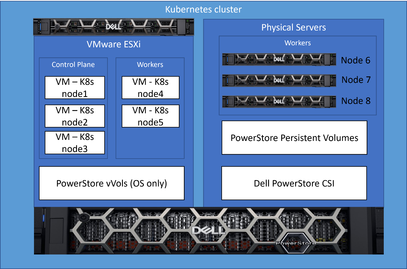
What kind of mess is this?!?
As the reader, you’re probably thinking…what kind of hodge-podge maintenance nightmare is this? I have K8s nodes that aren’t all the same and then some hacked up solution to make it work?!? Well, it’s not a mess at all, allow me to explain how it’s quite simple and elegant.
For those new to K8s, implementing something like this probably seems very complicated and hard to manage. After all, the workload should only run on the physical K8s nodes that are connected though Fiber Channel. Outside of K8s, Dell CSI, and the features they provide, it likely would be a mess of scripting and dependency checking.
An elegant solution!
In this solution I leveraged the labels and scheduling features of K8s with the PowerStore CSI features to implement a simple solution to accomplish this. This implementation is very clean and easy to maintain with no complicated scripts or configuration to maintain.
Step 1 – PowerStore CSI Driver configuration
As part of the PowerStore CSI driver configuration, one of the supported features (node selection) is the ability to select the nodes on which the K8s pods (in this case the CSI driver) will run, by using K8s labels. In the following figure, in the driver configuration, I specify that the PowerStore CSI driver should only run on nodes that contain the label “fc=true”. The label itself can contain any value; the key is that this value must match in a search.
The following is an excerpt from the Dell PowerStore CSI configuration file showing how this is done.
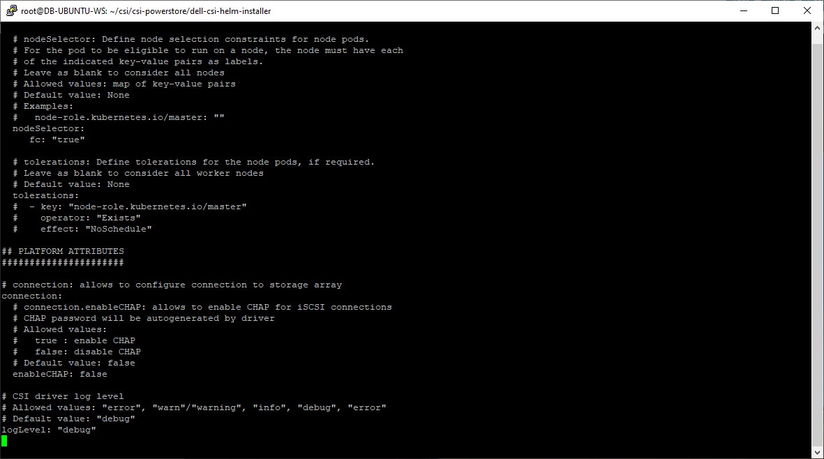
This is a one-time configuration setting that is done during Dell CSI driver deployment.
Step 2 – Label the physical nodes
The next step is to apply a label “fc=true” to the nodes that contain a Fibre Channel configuration on which we want the node to run. It’s as simple as running the command “kubectl label nodes <your-node-name> fc=true”. When this label is set, the CSI driver pods will only run on K8s nodes that contain this label value.
This label only needs to be applied when adding new nodes to the cluster or if you were to change the role of this node and remove it from this workload.
Step 3 – Let Kubernetes do its magic
Now, I leverage basic K8s functionality. Kubernetes resource scheduling evaluates the resource requirements for a pod and will only schedule on the nodes that meet those requirements. Storage volumes provided by the Dell PowerStore CSI driver are a dependency for my workload pods, and therefore, my workload will only be scheduled on K8s nodes that can meet this dependency. Because I’ve enabled the node selection constraint for the CSI driver only on physical nodes, they are the only nodes that can fill the PowerStore CSI storage dependency.
The result of this configuration is that the three physical nodes that I labeled are the only ones that will accept my performance workload. It’s a very simple solution that requires no complex scripting or configuration.
Here is that same architecture diagram showing the nodes that were labeled for the workload.
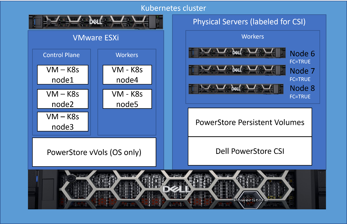
Kubernetes brings lots of exciting new capabilities that can provide elegant solutions to complex challenges. Our latest collaboration with Microsoft utilized this architecture. For complete details, see our latest joint white paper: Dell PowerStore with Azure Arc-enabled Data Services which highlights performance and scale.
Also, for more information about Arc-enabled SQL Managed Instance and PowerStore, see:
- the Microsoft blog post: Performance benchmark of Azure Arc-enabled SQL Managed Instance
- the Microsoft digital events Microsoft Build and Azure Hybrid, Multicloud, and Edge Day
Author: Doug Bernhardt
Sr. Principal Engineering Technologist

Intro to Native Metro Volume Support with a PowerStore CLI Example
Wed, 27 Jul 2022 13:50:50 -0000
|Read Time: 0 minutes
Introduction
With native metro volume support, PowerStoreOS 3.0 introduces an additional feature that helps prevent your production from outages caused by a failure in your VMware vSphere Metro Storage Cluster (vMSC) environment. The Metro Volume feature is available at no additional cost on PowerStore and can be used to protect VMFS datastores.
A vMSC configuration is a stretched cluster architecture where ESXi hosts can be in two different sites in metro distance (100 km / 60 miles) while accessing a synchronously replicated storage resource. The PowerStore Metro Volume feature provides concurrent and full active/active host IO on both participating PowerStore cluster configurations.
Although this adds additional latency, a PowerStore Metro Volume ensures that all host I/O is committed on both mirror volumes of a Metro Volume before the host receives an acknowledgement for the write I/O. To survive a disaster with minimal, or even better, no interruption to your production, PowerStore has built in a mechanism to protect your data from a split-brain situation in case of a failure or disaster. PowerStore is designed to allow only active-active workloads on both sides of a Metro Volume when data can be replicated between the Metro Volume mirrors on both PowerStore clusters.
From a topology point of view, PowerStore supports two different configuration scenarios. There is a Non-Uniform configuration where hosts only have access to the local PowerStore system:
There is also a Uniform configuration where hosts can access both the local and remote PowerStore.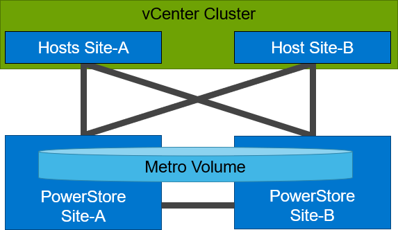
Even though they look similar, the benefits of the different topologies are in the details.
A Non-Uniform host configuration reduces complexity because it requires less configuration and only provides local access to the volume that has the least utilization on the link between the two sites. However, in a failure situation with the local PowerStore array, or during a link failure, local hosts can lose access to the Metro Volume. In this situation, VMware HA needs to restart any VMs on the affected datastore using the surviving hosts on the opposite site. There should be sufficient host resources available on each site to allow running the most critical VMs while the peer site is not available.
In a Uniform host configuration, the hosts have additional links to the remote PowerStore cluster that can be used during a failure situation. If the Metro Volume is not accessible on the local PowerStore cluster due a failure or link outage, the hosts can utilize the cross links to access the volume on the remote site. In this scenario, a VM could survive the failure because hosts can switch the working path to the remote system. Under normal operations, the host I/O should be kept within the local site to avoid unnecessary bandwidth utilization on the link between the sites for the workload and to minimize latency.
Let me show you a quick example where we assume a theoretical local latency of 0.5ms and 2ms between the sites.
1. The host is using a link to the local array as primary path to write to a Metro Volume. The theoretical latency for the I/O would be as follows:
- 0.5ms workload from the host to the local storage
- 2.0ms to replicate the workload to the remote storage. Workload uses a link between the sites.
- 2.0ms to receive the commit from the remote storage on the local storage
- 0.5ms for the commit to the host
In total, we would see a 5.0ms latency for the I/O and the workload is sent only once across the link between the sites for replication (A-B).
2. When the host is using the links to the remote array as primary path, we would see following situation:
- 2.0ms to send the workload to the remote storage. The workload uses a link between the sites.
- 2.0ms to replicate the workload to a peer. The workload uses a link between the sites.
- 2.0ms for the commit from the peer array to the remote storage
- 2.0ms for the commit to the host
In total, we would see a theoretical latency of 8.0ms for the same I/O because the workload and commits are always utilizing the link between the sites: once, when host writes data to the remote array (A to B), and again when the write is replicated to peer storage (B-A) plus the required commits.
To ensure the selection of optimal paths, PowerStore provides information for optimal path selection using the Asynchronous Logical Unit Access (ALUA) protocol. For the correct ALUA state, uniform hosts must be registered with their local or remote relation to each PowerStore cluster. There are four options when registering a host in PowerStore Manager:
- Local only – Used for Non-Uniform Metro Volumes and hosts serving only standard volumes.
- Host Co-Located with this PowerStore system – Indicates that the host is local (low latency) to the PowerStore, and should get the ALUA active/optimized paths.
- Host Co-Located with remote PowerStore system – Indicates that the host is a remote host (high latency), and host should get ALUA active/non-optimized paths.
- Host is Co-Located with both – Indicates that all hosts and PowerStore clusters are located in the same location with the same latency.
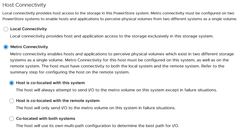
When a host is configured with a metro connectivity option for Uniform Metro Volume, PowerStore provides default ALUA path information for non-metro volumes standard volumes.
With Native Multipathing’s (NMP) default path selection policy (PSP) of “round robin” (RR), the connected ESXi hosts use the provided ALUA path information to determine the optimal working path down to the volume. When more than one active/optimized path is available, ESXi PSP round robin measures the latency to the volume to select the most optimal working path. The current working path is indicated with the status “Active (I/O)” in vCenter, while other paths only show the status “Active”. The following figure shows the path states for an ESXi host in a Uniform host configuration after a Metro Volume configuration is finished.
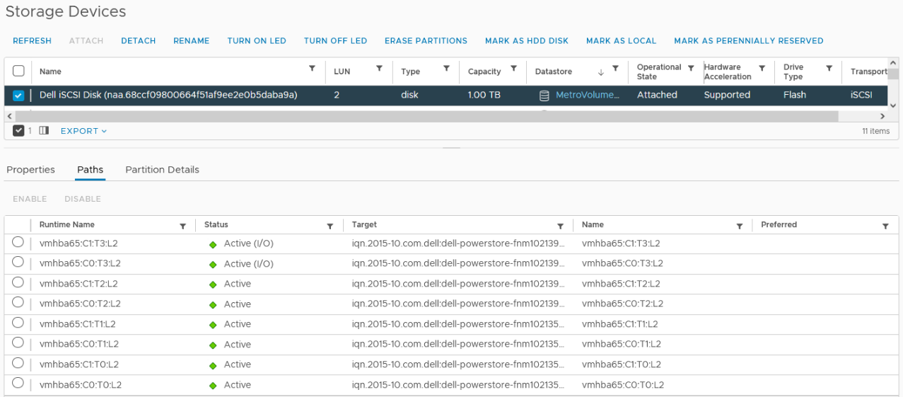
After hosts are set up in PowerStore manager, we can start to configure a Metro Volume. This is possible in just a few steps on a single PowerStore cluster:
- To set up a Remote Systems relationship with the peer PowerStore, select Protection > Add Remote System.
- Use the Add Volume wizard to create and map a standard volume.
- In the Volumes page, configure a Metro Volume with six clicks.
a. Select the new volume.
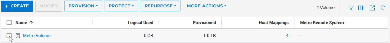
b. Click Protect.
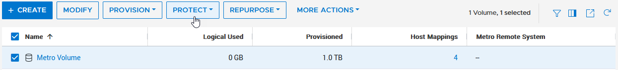
c. Configure Metro Volume
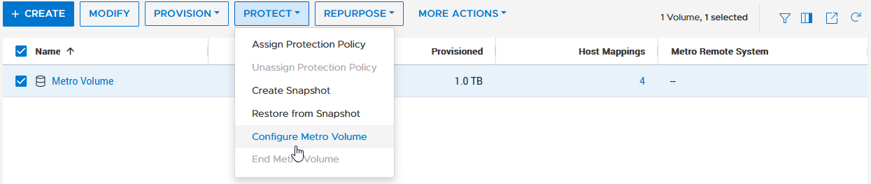
d. Click on the Remote System pull down.
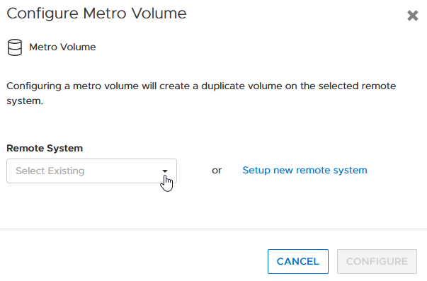
e. Select an existing remote system (or set up a new remote system relationship with another PowerStore cluster).
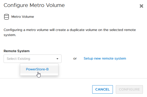
f. Click configure to start the configuration.
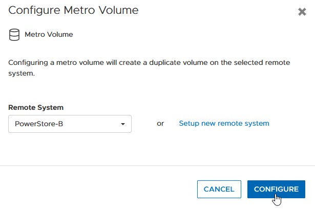
4. On the peer PowerStore cluster, map the new Metro Volume to the hosts.
5. Use the new Metro Volume to create a VMFS datastore.
Aside from using PowerStore Manager, it’s also possible to use the PowerStore REST API or the PowerStore CLI to set up a Metro Volume in just a few steps. In this blog, I want to show you the required steps in a PowerStore CLI session (pstcli -d <PowerStore> -session) to set up Metro Volume on PowerStore on a configured pair of PowerStore systems (as shown in the previous figure) for uniform host connectivity:
1. On PowerStore Manager PowerStore-A
a. Create Remote Systems relationship:
x509_certificate exchange -service Replication_HTTP -address <IP-Address PowerStore-B> -port 443 -username admin -password <YourSecretPassword>
 remote_system create -management_address <IP-Address PowerStore-B> -management_port 443 -remote_username admin -remote_password <YourSecretPassword> -type PowerStore -data_network_latency Low
b. Register ESXi hosts for Uniform host connectivity:
host create -name esx-a.lab -os_type ESXi -initiators -port_name iqn.1998-01.com.vmware:esx-a:<…>:65 -port_type iSCSI -host_connectivity Metro_Optimize_Local
host create -name esx-b.lab -os_type ESXi -initiators -port_name iqn.1998-01.com.vmware:esx-b:<…>:65 -port_type iSCSI -host_connectivity Metro_Optimize_Remote
c. Prepare and map a standard volume:
volume create -name MetroVolume-Uniform -size 1T
volume -name MetroVolume-Uniform -attach esx-a.lab
volume -name MetroVolume-Uniform -attach esx-b.lab
d. Configure the volume as a Metro Volume:
volume -name MetroVolume-Uniform configure_metro -remote_system_name PowerStore-B
2. On PowerStore Manager PowerStore-B
a. Register ESXi hosts for Uniform host connectivity:
host create -name esx-a.lab -os_type ESXi -initiators -port_name iqn.1998-01.com.vmware:esx-a:<…>:65 -port_type iSCSI -host_connectivity Metro_Optimize_Remote
host create -name esx-b.lab -os_type ESXi -initiators -port_name iqn.1998-01.com.vmware:esx-b:<…>:65 -port_type iSCSI -host_connectivity Metro_Optimize_Local
b. Map Volume to ESXi hosts:
volume -name MetroVolume-Uniform -attach esx-a.lab
volume -name MetroVolume-Uniform -attach esx-b.lab
c. Monitor Metro Volume (optional):
replication_session show -query type=Metro_Active_Active -select state,progress_percentage,data_transfer_state
3. In vCenter
a. Rescan the SCSI bus.
b. Configure the VMFS datastore with the new Metro Volume.
For more information, see the following resources.
Resources
- vSphere Metro Storage Cluster (vMSC)
- White paper: Dell PowerStore: Metro Volume
- White paper: Dell PowerStore: Replication Technologies
Author: Robert Weilhammer, Principal Engineering Technologist

Dell Technologies Has the Storage Visibility You’re Looking For!
Tue, 19 Jul 2022 14:31:27 -0000
|Read Time: 0 minutes
It’s no secret that high-performance storage is crucial for demanding database workloads. Database administrators (DBAs) work diligently to monitor and assess all aspects of database performance -- and storage is a top priority. As database workloads grow and change, storage management is critical to meeting SLAs.
How do you manage what you can’t see?
As a former DBA, one of the challenges that I faced when assessing storage performance and troubleshooting storage latency was determining root cause. Root cause analysis requires an end-to-end view to collect all data points and determine where the problem lies. It’s like trying to find a water leak, you must trace the route from beginning to end.
This becomes more complicated when you replace a single disk drive with a drive array or modern storage appliances. The storage is no longer part of the host, so from an operating system (OS) perspective, storage visibility is lost beyond the host. Popular third party monitoring tools don’t solve the problem because they don’t have access to that information either. This is where the finger pointing begins between storage administrators and DBAs because neither has access (or understanding) of the other side.
Stop the finger pointing!
Dell Technologies heard the need to provide end-to-end storage visibility and we have listened. Kubernetes brings a lot of production-grade capabilities and frameworks, and we are working to leverage these wherever possible. One of these is storage visibility, or observability. Now, everyone who works with Kubernetes (K8s) can view end-to-end storage metrics on supported Dell Storage appliances! DBAs, storage administrators, and developers can now view the storage metrics they need, track end-to-end performance, and communicate effectively.
How does it work?
The Dell Container Storage Module (CSM) for Observability is an OpenTelemetry agent that provides volume-level metrics for Dell PowerStore and other Dell storage products. The Dell CSM for Observability module leverages Dell Container Storage Interface (CSI) drivers to communicate with Dell storage. Metrics are then collected from the storage appliance and stored in a Prometheus database for consumption by popular monitoring tools that support a Prometheus data source such as Grafana. Key metrics collected by CSM observability include but are not limited to:
- Storage pool consumption by CSI Driver
- Storage system I/O performance by Kubernetes node
- CSI Driver positioned volume I/O performance
- CSI Driver provisioned volume topology
Let’s take a look
Let’s walk through a quick end-to-end example. A familiar display from SQL Server Management Studio shows the files and folders that comprise our tpcc database:
Now we need to translate that into K8s storage terms. Using meaningful naming standards for Persistent Volume Claims will negate a lot of this process, but it’s good to know how it all ties together!
A SQL Server pod will contain one or more Persistent Volume Claims (unless you don’t want to persist data 😊). These represent storage volumes and are presented to the SQL Server instance as a mount point.
The following example shows the deployment definition for our SQL Server pod with one of the mount points and Persistent Volume Claims highlighted. By examining the pod deployment, we can see that the folder/mount point /var/opt/mssql presented to SQL Server is tied to the K8s volume mssqldb and the underlying persistent volume claim mssql-data.
apiVersion: apps/v1
kind: Deployment
metadata:
  name: mssql-deployment
spec:
  replicas: 1
  selector:
     matchLabels:
       app: mssql
  template:
    metadata:
      labels:
        app: mssql
    spec:
       terminationGracePeriodSeconds: 30
      hostname: mssqlinst
      securityContext:
        fsGroup: 10001
      containers:
      - name: mssql
        image: mcr.microsoft.com/mssql/server:2019-latest
        ports:
        - containerPort: 1433
        resources:
          limits:
            cpu: "28"
            memory: "96Gi"
          requests:
            cpu: "14"
            memory: "48Gi"
        env:
        - name: MSSQL_PID
          value: "Developer"
        - name: ACCEPT_EULA
          value: "Y"
        - name: SA_PASSWORD
          valueFrom:
            secretKeyRef:
              name: mssql
              key: SA_PASSWORD
        volumeMounts:
        - name: mssqldb
          mountPath: /var/opt/mssql
        - name: mssqldb2
          mountPath: /var/opt/mssql2
        - name: mssqllog
          mountPath: /var/opt/mssqllog
      volumes:
      - name: mssqldb
         persistentVolumeClaim:
          claimName: mssql-data
      - name: mssqldb2
         persistentVolumeClaim:
          claimName: mssql-data2
      - name: mssqllog
         persistentVolumeClaim:
          claimName: mssql-log
Following that example, you can see how the other Persistent Volume Claims, mssql-data2 and mssql-log are used by the SQL Server database files. The following figure shows one of the Grafana dashboards that makes it easy to tie the Persistent Volume Claims for the mssql-data, mssql-data2, and mssql-log used by the SQL Server pod to the Persistent Volume name.
From here, we can use the Persistent Volume name associated with the Persistent Volume Claim to view metrics on the storage appliance, or better yet, in another Grafana dashboard.
The following example shows the PowerStore Volume I/O Metrics dashboard. The key storage metrics (IOPS, latency, and bandwidth) are displayed as reported by the Dell PowerStore storage appliance.

You can select any of the charts for expanded viewing. The Volume Read Latency chart is selected below.
Rapid Adoption
These Kubernetes frameworks are becoming popular, and adoption is happening rapidly. Microsoft SQL Server Big Data Clusters and their latest offering Azure Arc-enabled SQL Managed Instance both display SQL statistics in Grafana as well. This allows single pane of glass viewing for all your key SQL metrics!

Kubernetes and cloud-native design are here to stay. They bridge the gap between cloud and on-premises deployments and the wealth of capabilities provided by K8s make it impossible to ignore.
Dell Technologies is leading the way with PowerStore capabilities as well as the full Dell portfolio of products. We are working diligently with partners such as Microsoft to prove out new technologies so you can modernize your data estate with confidence!
For more information about Azure Arc-enabled SQL Managed Instance and PowerStore, see:
- Our latest joint white paper: Dell PowerStore with Azure Arc-enabled Data Services which highlights performance and scale.
- The Microsoft blog post: “Performance benchmark of Azure Arc-enabled SQL Managed Instance.”
- The Microsoft digital events Microsoft Build and Azure Hybrid, Multicloud, and Edge Day.
Author: Doug Bernhardt
Sr. Principal Engineering Technologist

Thinking About How to Import from VNX2 File Storage Environments?
Wed, 13 Jul 2022 09:30:08 -0000
|Read Time: 0 minutes
In the world today, many users are overwhelmed with the rapid pace of technology and innovation. Businesses are growing at swift rates and many users know they need to migrate off of older storage hardware that may be under heavy load or running out of support.
Dell PowerStore has made it simple to import other storage systems through orchestration wizards so that users can get their existing data up and running quickly on the new technology. Previous versions of PowerStoreOS allowed for block import — and now, we have come full circle to support file import!
PowerStoreOS 3.0 and higher now supports importing virtual data movers (VDMs) and their filesystems from the Dell VNX2 system. This includes both NFS and SMB file systems. Users can natively import their data without any special migration solution or hardware required. PowerStore handles all the creation, monitoring, and management.
This blog provides a quick high-level overview of the import stages. For additional details, see also a video that shows this process.
The file import workflow contains six major steps:
- Prepare VNX system
- Prepare PowerStore system
- Add Remote System
- Create Import Session
- Cutover Import Session
- Commit Import Session
Step 1 – Ensure that your VNX2 has the proper code levels and connectivity to talk to the PowerStore system. (For the latest details, see the PowerStore documentation listed at the bottom of this blog.)
Step 2 – Verify that the PowerStore system is running PowerStoreOS 3.0 or higher, and has the “file mobility network” configured. You can configure this network by selecting Settings -> Networking -> Network IP’s under “File Mobility”.
Step 3 – Add the remote system by navigating to Migration -> Import External Storage from the PowerStore management console, as shown here.
Step 4 – Create the import session. This is where you select the VNX2 VDM for import. The host is still accessing data on the VNX2. A connection is established, and resources are created on the target PowerStore. Cold data is now being copied to the PowerStore, as shown here.
Step 5 – The cutover import session begins. Data is copied from the source VNX2 to the PowerStore, which then services the read requests from the host. Data that remains on the VNX2 is read from it. Incoming writes are mirrored to the VNX2 and to the PowerStore system, The data continues to be copied in the background to the PowerStore, as shown in the following figure.
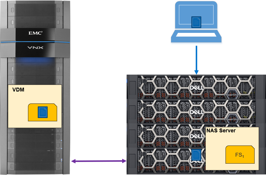
Step 6 – the final step, commits the import session. When all the data has been transferred from the VNX2 to the PowerStore, the state will show “Ready for Cutover”, and you can commit the import session. This will suspend the write mirroring: the session cannot be rolled back from this point. This process will also clean up the source VNX2 system. Because the import has completed, the data is now being accessed just from the PowerStore (as in the following figure).
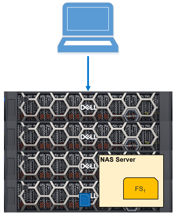
Conclusion
I’ve outlined just a few of the import and migration features in the Dell PowerStoreOS 3.0 release. For more information about these and other features in this release, check out these resources:
- PowerStore: Migration Technologies
- Dell Technologies Info Hub
- Dell PowerStore Simple Support Matrix
- Video: Dell PowerStore: Import Dell VNX File Resources
Author: Andrew Sirpis

PowerStore: The Perfect Choice for Azure Arc-enabled Data Services
Tue, 12 Jul 2022 12:57:39 -0000
|Read Time: 0 minutes
Keeping pace with technology can be tough. Often our customers’ resources are stretched thin, and they want to be confident that the solutions offered by Dell Technologies are up to the task. Dell Technologies performs an astonishing amount of work to prove out our products and give customers confidence that we have done our homework to make customers' experiences the best they can be. Additionally, we work with partners like Microsoft whenever possible to ensure that our integrations are world class as well.
Great partnership
Recently we partnered with Microsoft on one of their newest and most exciting offerings in the Microsoft Data Platform, Azure Arc-enabled SQL Managed Instance. This exciting new product deploys containerized SQL Server in a High Availability (HA) configuration on the infrastructure of your choice. This new offering allows SQL Server instances to be deployed on-premises, yet deployed through and monitored by Azure.
Dell Technologies collaborated with Microsoft to plan and perform lab testing to evaluate the performance and scale of Azure Arc-enabled SQL Managed Instance. Based on that plan, we executed several test scenarios and submitted the test configuration and results to Microsoft for review.
Dell PowerStore: the perfect storage solution
Due to the HA features of Azure Arc-enabled SQL Managed Instance, Kubernetes ReadWriteMany (RWX) storage is recommended as a backup target and a typical implementation of this is a Network File Share (NFS). Typically, this would require two storage devices, one for block (database files) and one for file (database backup), or an NFS server backed by block storage. PowerStore is uniquely suited to meet this storage requirement, offering both block and file storage in the same appliance. PowerStore also offers all-flash performance, containerized architecture, and data services such as data reduction, replication, and encryption for demanding database workloads. Dell PowerStore meets all the feature and performance requirements for Azure Arc-enabled SQL Managed Instance in a single appliance.
Incredible results
In our testing, we deployed SQL Managed Instance by means of the Azure portal onto our on-prem Kubernetes cluster and put it through its paces to assess performance and scale. The configuration that we used was not sized for maximum performance, but an average configuration that is typical of what customers order for a general-purpose workload. The results were incredible!
The slide below, presented by Microsoft at Microsoft Build 2022, summarizes it nicely!

The full Microsoft Build session where this slide was presented can be found here. Other details are covered in a Microsoft Blog Post: “Performance benchmark of Azure Arc-enabled SQL Managed Instance.” Complete details and additional benefits are covered in our co-authored whitepaper, “Dell PowerStore with Azure Arc-enabled Data Services.”
For even more background on the work Dell Technologies is doing with Microsoft to enable hybrid, multicloud, and edge solutions, see this on-demand replay of the Azure Hybrid, Multicloud, and Edge Day digital event.
We learned a lot from this project. Stay tuned for additional blogs about more of the great findings from our latest collaborative effort!
Author: Doug Bernhardt, Sr. Principal Engineering Technologist

What's New In PowerStoreOS 3.0?
Wed, 06 Jul 2022 11:44:44 -0000
|Read Time: 0 minutes
Introduction
Dell PowerStoreOS 3.0 marks the third major release for the continuously modern PowerStore platform. While it is the third release, 3.0 is the largest PowerStore release to date, with over 120 new features. This release includes 80% more features compared to the PowerStoreOS 1.0 release! Beyond new features, there were radical performance and scalability boosts packed in too. Up to 50% faster mixed workloads, 70% faster writes, 10x faster copy operations, and 8x more volumes ensure PowerStore can handle all your workloads. Let’s take a quick look at all the new content in this release.
PowerStoreOS 3.0
PowerStoreOS 3.0 is a major release for PowerStore, including new software capabilities alongside the first PowerStore platform refresh.
- Platform: New PowerStore models bring newer Intel® Xeon® processors and secure boot capabilities with hardware root of trust (HWRoT) to the PowerStore family. Additional improvements include a brand new all NVMe expansion enclosure and a 100 GbE front end card for even faster Ethernet connectivity.
- Data Mobility: File replication, vVol replication, and synchronous Metro Volume replication greatly enhance PowerStore’s data mobility capabilities.
- Enterprise File: File gets a boost with CEPA support for file monitoring, file level retention (FLR), and file on all ports through user defined link aggregations.
- VMware Integration: Beyond the data mobility enhancement with vVol replication, PowerStore adds VMFS and NFS virtual machine visibility, VMware file system type for NFS datastores, and vVol over NVMe.
- Security: External Key Manager (KMIP) and FIPS 140-2 certified NVRAM drives all enhance the security of PowerStore.
- Native Import: Support for two new source platforms, Fibre Channel import connectivity, and native file import make it easier than ever to migrate resources to PowerStore.
- PowerStore Manager: A multitude of additional enhancements makes PowerStore even simpler, more intelligent, and incredibly efficient to manage.
Now that I’ve summarized the newest release, let’s dive into the details to really understand what’s being introduced.
Platform
PowerStore Family
PowerStore is a 2U, two node, purpose built platform that ranges from the PowerStore 500 up to the new PowerStore 9200. The two model types (PowerStore T and PowerStore X) are denoted by the letter T or X at the end of the model number. In PowerStoreOS 3.0, four new PowerStore T models have been introduced, ranging from PowerStore 1200T up to PowerStore 9200T. These appliances feature the same dual-node architecture with upgraded dual-socket Intel® Xeon® processors and are supported on PowerStoreOS 3.0 and higher software.
The following two tables outline the next generation PowerStore models, including the PowerStore 500 and the new 1200-9200 models (Table 1), and the original PowerStore models available at the launch of PowerStoreOS 1.0 (Table 2).
Table 1. PowerStore 500 and 1200-9200 model comparison1
| PowerStore 500T | PowerStore 1200T | PowerStore 3200T | PowerStore 5200T | PowerStore 9200T |
NVRAM drives | 0 | 2 | 4 | ||
Maximum storage drives (per appliance) | 97 | 93 | |||
Supported drive types | NVMe SCM2, NVMe SSD | ||||
4-port card | 25/10 GbE optical/SFP+ and Twinax3 | 25/10 GbE optical/SFP+ and Twinax or 10GbE BASE-T | |||
2-port card | 10 GbE optical/SFP+ and Twinax | 100 GbE QSFP 4 | |||
Supported I/O modules | 32/16/8/4 Gb FC 100 GbE optical/QSFP and copper active/passive5 25/10 GbE optical/SFP+, and Twinax 10 GbE BASE-T | ||||
Supported expansion enclosures | Up to three 2.5-inch 24-drive NVMe SSD enclosures per appliance | ||||
1 PowerStore 500 and 1200 through 9200 models only offered as a PowerStore T.
2 NVMe SCM SSDs only supported in base enclosure.
3 Ports 2 and 3 on the 4-Port card on PowerStore 500 are reserved for NVMe expansion enclosure.
4 2-port card is reserved for back-end connectivity to NVMe expansion enclosure on PowerStore 1200 through 9200
5 PowerStore 500 does not support the 100 GbE I/O module.
Table 2. PowerStore 1000-9000 model comparison
| PowerStore 1000 | PowerStore 3000 | PowerStore 5000 | PowerStore 7000 | PowerStore 9000 |
NVRAM drives | 2 | 4 | |||
Maximum storage drives (per appliance) | 96 | ||||
Supported drive types | NVMe SCM1, NVMe SSD, SAS SSD2 | ||||
4-port card | 25/10 GbE optical/SFP+ and Twinax | ||||
2-port card | - | ||||
Supported I/O modules | 32/16/8 Gb FC or 16/8/4 Gb FC 100 GbE optical/QSFP and copper active/passive (PowerStore T only) 25/10 GbE optical/SFP+/QSFP and Twinax (PowerStore T only) 10 GbE BASE-T (PowerStore T only) | ||||
Supported expansion enclosures | 2.5-inch 25-drive SAS SSD | ||||
1 NVMe SCM drives only supported in base enclosure.
2 SAS SSD drives only supported in SAS expansion enclosure.
NVMe Expansion Enclosure
Starting In PowerStoreOS 3.0, the PowerStore 500, 1200, 3200, 5200, and 9200 model systems support 24-drive 2U NVMe expansion enclosures (see Figure 1) using 2.5-inch NVMe SSD drives for extra capacity. NVMe expansion enclosures do not support NVMe SCM drives. The base enclosure can support all NVMe SSDs or a mix of NVMe SSDs and NVMe SCM drives (for meta data tier) with an NVMe expansion enclosure attached. Prior to attaching an NVMe expansion enclosure, all drive slots 0 to 21 in the base enclosure must be populated. Each appliance in a PowerStore cluster supports up to three NVMe expansion enclosures.
This enables each appliance to scale to over 90% more expansion capacity when compared to using a SAS expansion enclosure. The NVMe expansion enclosure (as shown here) can result in a 66% increase in the maximum effective capacity of a cluster. PowerStore can now support over 18 PBe capacity on each cluster!
100 GbE Front End Connectivity
PowerStoreOS 3.0 also introduces a new 100 GbE optical I/O module that supports QSFP28 transceivers running at 100 GbE speeds. The 100 GbE I/O module must be populated into I/O module slot 0 on each node of the PowerStore appliance. This I/O module supports file, NVMe/TCP, iSCSI traffic, replication, and import interfaces.
Data mobility
Metro Volume
PowerStoreOS 3.0 and higher supports synchronous block replication with the Metro Volume feature. Metro Volume can be used for disaster avoidance, application load balancing, and migration scenarios. This provides active-active IO to a metro volume spanned across two PowerStore clusters. It supports FC or iSCSI connected VMware ESXi hosts for VMFS datastores. A Metro Volume can be configured easily and quickly in as little as six clicks!
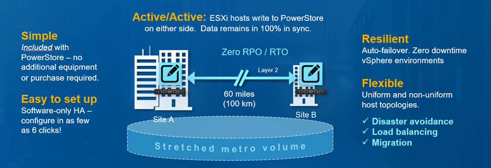
File Replication
Starting with PowerStoreOS 3.0, asynchronous file replication is now available. Asynchronous replication can be used to protect against a storage-system outage by creating a copy of data to a remote system. Replicating data helps to provide data redundancy and safeguards against failures and disasters at the main production site. Having a remote disaster recovery (DR) site protects against system and site-wide outages. It also provides a remote location that can resume production and minimize downtime due to a disaster.
vVol Replication
PowerStoreOS 3.0 brings support for asynchronous replication for vVol-based virtual machines. This feature uses VMware Storage Policies and requires VMware Site Recovery Manager instances at both sites. Asynchronous replication for vVol-based VMs uses the same snapshot-based asynchronous replication technology as native block replication.
Enterprise File
Common Event Publishing Agent (CEPA)
PowerStoreOS 3.0 introduces Common Event Publishing Agent (CEPA). CEPA delivers SMB and NFS file and directory event notifications to a server, enabling them to be parsed and controlled by third-party applications. You can implement this feature for use cases such as detecting ransomware, monitoring user access, configuring quotas, and providing storage analytics. The event notification solution consists of a combination of PowerStore, the Common Event Enabler (CEE) CEPA software, and a third-party application.
File Level Retention (FLR)
PowerStoreOS 3.0 also introduces File-Level Retention (FLR). FLR is a feature that can protect file data from deletion or modification until a specified retention date. This functionality is also known as Write-Once, Read-Many (WORM).
PowerStore supports two types of FLR: FLR-Enterprise (FLR-E) and FLR-Compliance (FLR-C). FLR-C has other restrictions and is designed for companies that must comply with federal regulations. The following table shows a comparison of FLR-E and FLR-C.
Table 3. FLR-E and FLR-C
Name | FLR-Enterprise (FLR-E) | FLR-Compliance (FLR-C) |
Functionality | Prevents file modification and deletion by users and administrators through NAS protocols such as SMB, NFS, and FTP | |
Deleting a file system with locked files | Allowed (warning is displayed) | Not allowed |
Factory reset (destroys all data) | Allowed | |
Infinite retention period behavior | Soft: A file locked with infinite retention can be reduced to a specific time later | Hard: A file locked with infinite retention can never be reduced (an FLR-C file system that has a file locked with infinite retention can never be deleted) |
Data integrity check | Not available | Available |
Restoring file system from a snapshot | Allowed | Not allowed |
Meets requirements of SEC rule 17a-4(f) | No | Yes |
File On All Ports
Starting with PowerStoreOS 3.0, you can configure user-defined link aggregations for file interfaces. This ability enables you to create custom bonds on two to four ports. The bond can span the 4-port card and I/O modules, but these components must have the same speed, duplex, and MTU settings. These user-designed link aggregations support NAS server interfaces, and allow you to scale file out to any supported Ethernet port.
VMware Integration
VMware Visibility
PowerStore natively supports visibility into vVol datastores, pulling all virtual machines hosted on PowerStore vVol datastores into PowerStore Manager for direct monitoring. With the introduction of PowerStoreOS 3.0, this VMware visibility is expanded to include NFS and VMFS datastores backed by PowerStore storage. File systems and volumes on PowerStore that are configured as NFS or VMFS datastores in vSphere will reflect the datastore name within PowerStore Manager. Any virtual machine deployed on those datastores will also be captured in PowerStore Manager and visible from both the virtual machines page or within the resource details page itself.
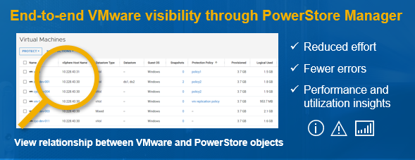
VMware File System
Starting with PowerStoreOS 3.0, an option to create a VMware file system is added. VMware file systems are designed and optimized specifically to be used as VMware NFS datastores. VMware file systems support AppSync for VMware NFS, Virtual Storage Integrator (VSI), hardware acceleration, and VM awareness in PowerStore Manager.
NVMe Storage Containers
PowerStoreOS 3.0 adds support to create either SCSI or NVMe storage containers. Before this release, all storage containers were SCSI by default. SCSI storage containers support host access through SCSI protocols, which include iSCSI or Fibre Channel. NVMe storage containers support host access through NVMe/FC protocols and allow for vVols over NVMe/FC.
Security
KMIP
PowerStoreOS 3.0 supports using external key-management applications. External key managers for storage arrays provide extra protection if the array is stolen. The system does not boot and data cannot be accessed if the external key server is not present to provide the relevant Key Encryption Key (KEK).
FIPS
Data at Rest Encryption (D@RE) in PowerStore uses FIPS 140-2 validated self-encrypting drives (SEDs) by respective drive vendors for primary storage (NVMe SSD, NVMe SCM, and SAS SSD). PowerStoreOS 3.0 also supports FIPS 140-2 on the NVMe NVRAM write-cache drives. With PowerStoreOS 3.0, all PowerStore models can now be FIPS 140-2 compliant.
Native Import
PowerStoreOS 3.0 introduces native file import. This feature enables you to import file storage resources from Dell VNX2 to PowerStore. This feature enables administrators to import a Virtual Data Mover (VDM) along with its associated NFS or SMB file systems. The creation, monitoring, and management of the migration session is all completed by PowerStore and has a similar user experience to native block import.

PowerStore Manager
PowerStoreOS 3.0 added a number of enhancements and new features to PowerStore Manager to improve the usability and efficiency of the system. I’ve summarized some of the key features in the management space below:
- Host Information – Initiators: The new initiators pane added to the Host Information page displays all initiators and initiator paths in one pane of glass for all supported protocols (iSCSI, FC, NVMe/FC, and NVMe/TCP).
- Snapshots Column: This new column added for the volumes, volume groups, file systems, and virtual machine list pages allows you to easily see how many snapshots are associated with a particular object.
- View Topology: This feature provides a hierarchy as a graphical family tree, making it easy and efficient to visualize the family relationship of a volume or volume group, snapshots, and thin clones.
- Performance Metrics: New five-second metrics allow you to specify certain resources with enhanced granularity, and even compare up to 12 resources of the same type in a single window.
- Automatic Software Downloads: With support connectivity enabled, this feature automatically downloads software packages to PowerStore to make upgrades even easier.
- Language Packs: This feature translates texts and adds specific local components for different regions.
Conclusion
As you can see, PowerStoreOS 3.0 is a huge release delivering a new second generation platform refresh and a huge set of features to allow our customers to boost their performance, innovate without limits, and remain continuously modern with the PowerStore platform.
Resources
Author: Ethan Stokes, Senior Engineering Technologist

Let’s Talk File (#4) – SMB Protocol Overview
Fri, 01 Jul 2022 19:28:26 -0000
|Read Time: 0 minutes
Introduction
A file access protocol enables clients and storage systems to transmit data using a common syntax and defined rules. PowerStore file supports a wide range of protocols, including SMB, NFS, FTP, and SFTP. In this blog, we’ll focus on a commonly used protocol for file sharing called Server Message Block (SMB). SMB is commonly used for use cases such as departmental shares, home directories, Microsoft SQL Server, Hyper-V, Exchange, and more.
SMB versions
The SMB option on the NAS server enables or disables SMB connectivity to the file systems.
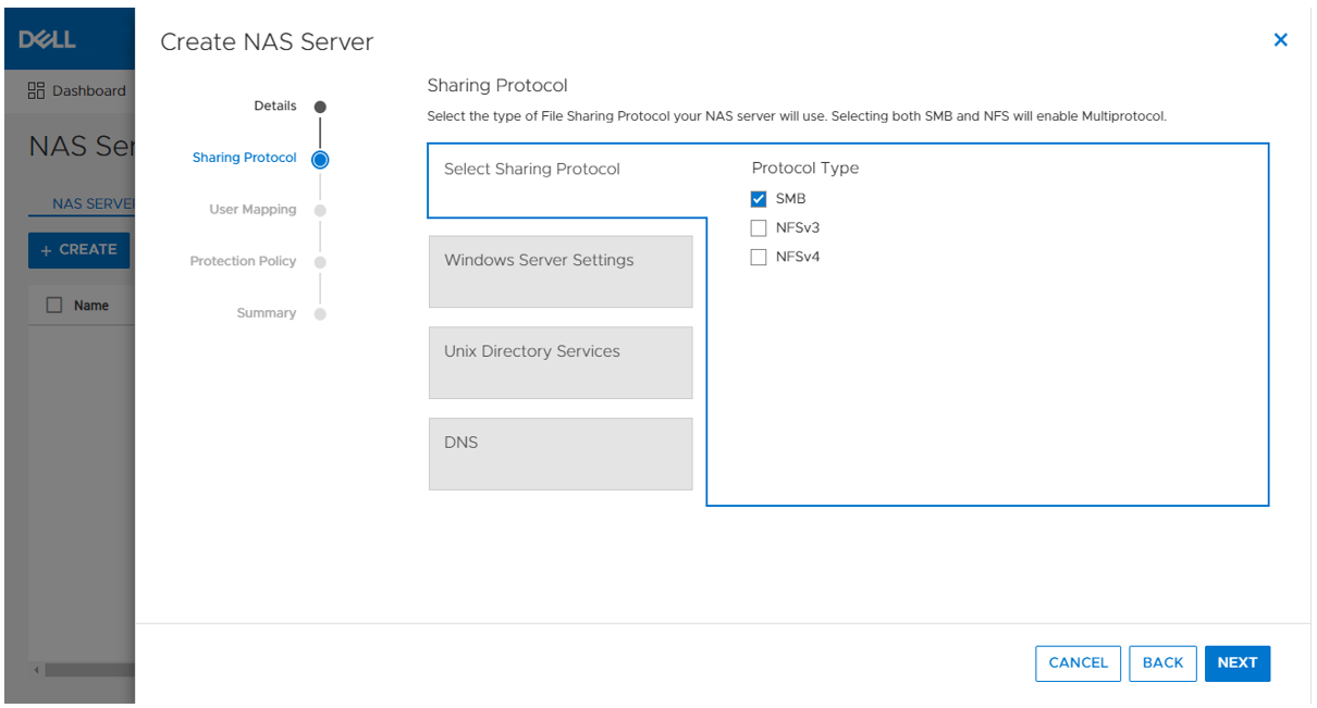
PowerStore file supports SMB1 through 3.1.1. The SMB version that is negotiated depends on the client operating system:
- CIFS: Windows NT 4.0
- SMB1: Windows 2000, Windows XP, Windows Server 2003, and Windows Server 2003 R2
- SMB2: Windows Vista (SP1 or later) and Windows Server 2008
- SMB2.1: Windows 7 and Windows Server 2008 R2
- SMB3.0: Windows 8 and Windows Server 2012
- SMB3.02: Windows 8.1 and Windows Server 2012 R2
- SMB3.1.1: Windows 10 and Windows Server 2016 and Windows Server 2019
Due to the age of the protocol and potential security vulnerabilities, client access using SMB1 is disabled by default. If client access using SMB1 is required, it can be enabled by modifying the cifs.smb1.disabled parameter. Using SMB2 at a minimum is recommended because it provides security enhancements and increases efficiency, as compared to SMB1.
NAS servers use SMB2 to communicate with the domain controllers for operations such as authentication, SID lookups, Group Policies, and so on. If SMB2 is not available, the NAS server attempts to use SMB1 as a backup option. This means that any domain controllers that are running older operating systems that only support SMB1 can continue to function.
Standalone SMB server configuration
When enabling SMB support on a NAS server, the SMB server can either be standalone or Active Directory (AD) domain-joined. Standalone SMB servers are not associated with an AD domain so they only support local authentication. The information required when configuring a new standalone SMB server is shown in the following table.
Name | Description |
Workgroup | Name of the Windows workgroup where the file systems will be shared. |
Netbios Name | Network name of the standalone SMB server (15 characters maximum). |
Administrator Password | Set the initial password for the local Administrator user. |
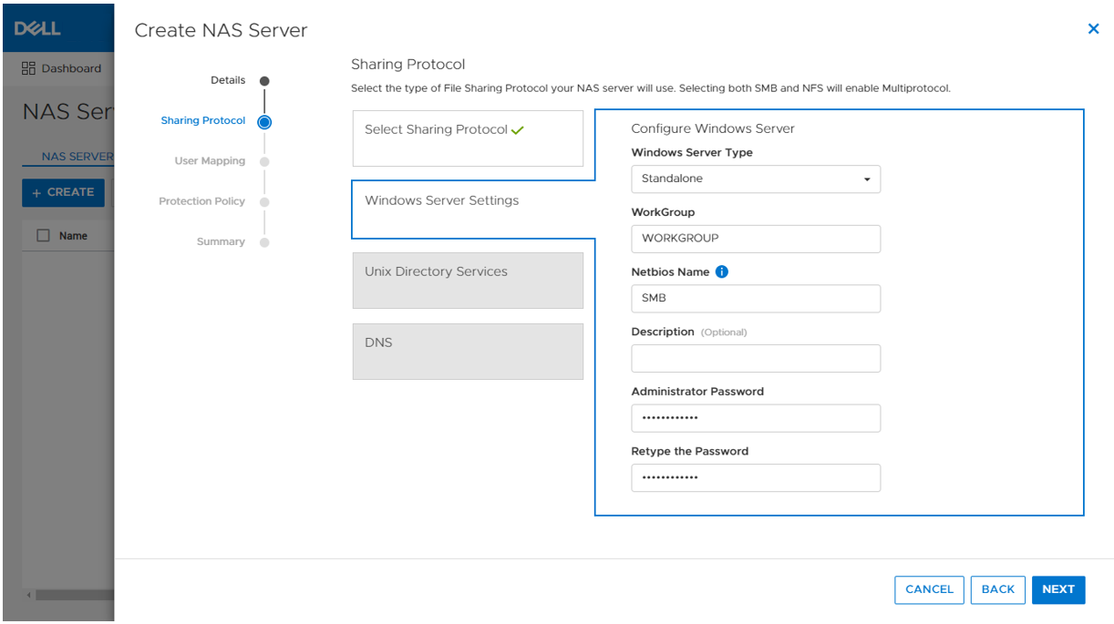
On the next step in the wizard, you can also optionally enable DNS on the standalone SMB server for IP address and name resolution.
When the SMB server is created, it’s designed to have the same behavior and support many of the same tools as a Windows server. The administrator can manage it using standard Microsoft Windows tools such as the Computer Management MMC Console. These are the same tools that are used to manage a standard Windows server deployment, reducing the learning curve for administrators who are transitioning to PowerStore. There are also lots of tutorials and applicable documentation available online.
You can connect to the standalone SMB server by connecting to another computer and specifying the IP address of the NAS server.
The local users are stored in the Local Users and Groups Database. Upon creation of a new standalone SMB server, only the local Administrator user is available. In the following figure, the Guest account is disabled by default, as noted by the down arrow at the bottom left corner of the Guest icon. Additional users and groups can be created here, if needed.
Domain-joined SMB server configuration
Domain-joined SMB servers are associated with an AD domain. AD is leveraged for centralized user authentication, applying group policies, enforcing security, implementing password requirements, and more.
The following information is required when configuring a new standalone SMB server:
Name | Description |
SMB Computer Name | Name of the computer object to be created in Active Directory |
Windows Domain | Name of the domain to which to join the SMB server |
Domain Username | Username of an account that has domain joining privileges |
Password | Password for the specified user |
As part of the domain joining process, a computer object is created in the AD domain and DNS entries are created for IP address and name resolution. Domain-joined SMB servers require DNS to be configured, but this configuration is optional for standalone SMB servers. Domain-joined NAS servers are placed in the CN=Computers container, by default. The computer object can be configured to be stored in a different OU location in the advanced settings.
SMB shares
When the SMB server is configured, you can provision a file system along with an SMB share. The SMB share provides a path that clients can map to access the file system. The initial SMB share can be created as part of the file system provisioning wizard. Additional SMB shares can also be created on existing file systems, as long as the path exists.
The figure below shows the SMB share step of the file system provisioning wizard. The only required field is the name for the share. On the right, you can also see the name of the NAS Server, local path, file system name, SMB server name, and the SMB share path for the share.
Take note of the SMB share path because that is what you will use to map the share from the client. This is called a UNC (Universal Naming Convention) path and the format is \\<SMB_Server>\<SMB_Share_Name>. For example, \\smb\fs.
You can disregard the other advanced SMB settings for now. We’ll cover those in a later blog.
Mapping a share
Now we are ready to map the share on a client. On a client, you can simply enter the UNC path into MS Explorer to access the share, as shown below.
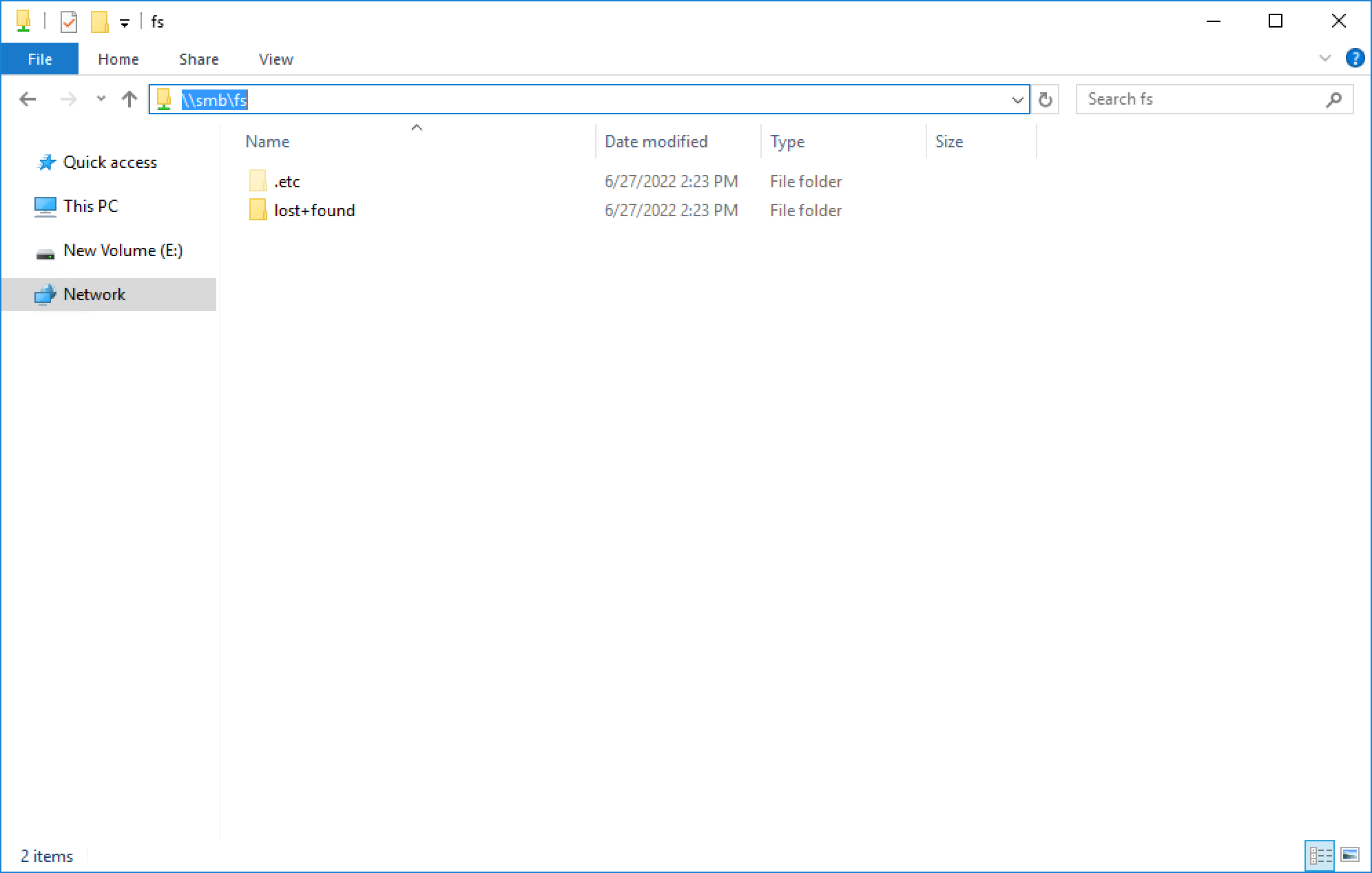
If your client is logged in using an account that is on the same domain as the domain-joined SMB server, your credentials are passed automatically and the share opens. If you’re attempting to map an SMB server that is in a foreign domain, you are prompted for credentials in order to access the share. Alternatively, you can also connect using a local user’s credentials.
For standalone SMB servers, you can only connect using a local user’s credentials. You are prompted for the username and password when connecting to the share. By default, only the local Administrator user exists and the password is set during the initial configuration of the standalone SMB server.
To map the share to a drive letter (so that you can easily access it in the future), click the Map Network Drive button in Explorer, as shown here.
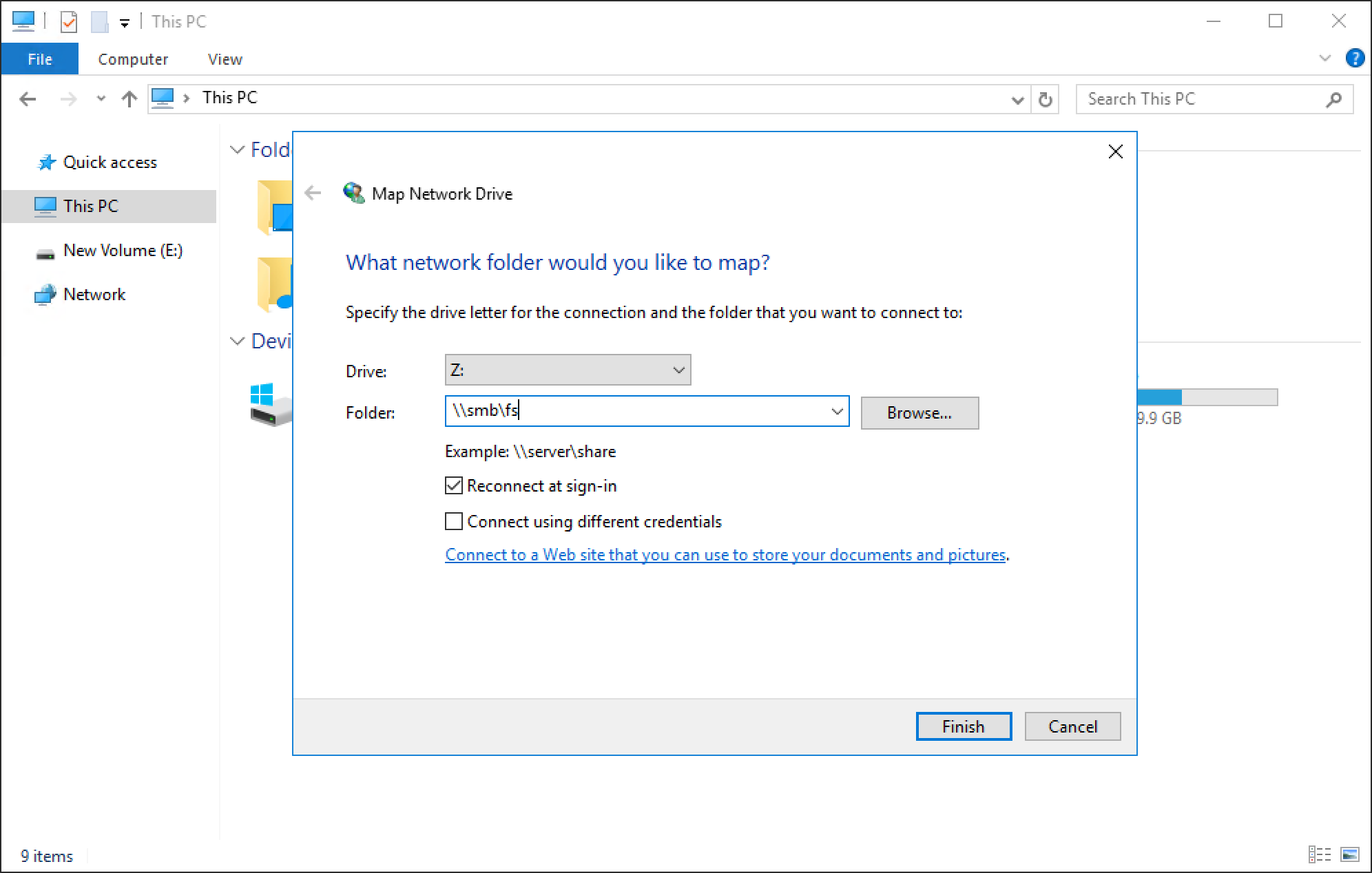
You can select a drive letter to which to map the drive, specify the UNC path, and select options such as reconnect at sign-in or connect using different credentials. When the drive is mapped, you can access it using the assigned drive letter, as shown in the following figure.
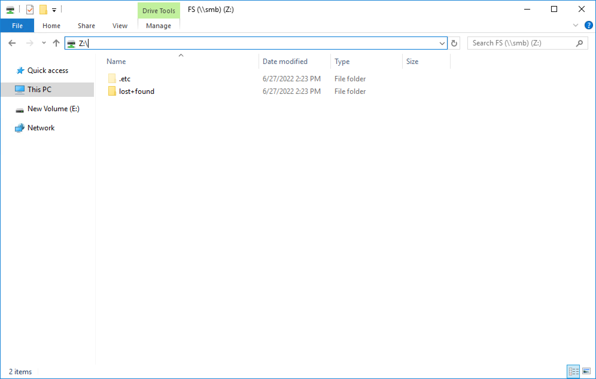
Conclusion
Great job! You are now familiar with how to use the SMB protocol for file system access. This enables you to start configuring environments using SMB for many use cases and applications. Stay tuned for the next blog in this series where we’ll take a look at another commonly used file protocol: NFS.
Resources
Author: Wei Chen, Senior Principal Engineering Technologist

Let’s Talk File (#3) – PowerStore File Systems
Thu, 12 May 2022 18:20:23 -0000
|Read Time: 0 minutes
Introduction
A file system is a storage resource that holds data and can be accessed through file sharing protocols such as SMB or NFS. The PowerStore file system architecture is designed to be highly scalable, efficient, performance-focused, and flexible. PowerStore offers a 64-bit file system that is mature and robust, enabling it to be used in many of the traditional NAS file use cases.
File system highlights
PowerStore file systems can accommodate large amounts of data, directories, and files. Each individual file system is designed to scale up to 256TB in size, hold 10 million subdirectories per directory, and store 32 billion files. Don’t forget that PowerStore can support up to 500 file systems on an appliance as well!
All file systems are thinly provisioned and always have compression and deduplication enabled. This means that capacity is allocated on demand as capacity is consumed on the file system. In addition, compression and deduplication help reduce the total cost of ownership and increase the efficiency of the system by reducing the amount of physical capacity that is needed to store the data. Savings are not only limited to the file system itself, but also to its snapshots and thin clones. Compression and deduplication occur inline between the system cache and the backend drives. The compression task is offloaded to a dedicated chip on the node, which frees up CPU cycles.
PowerStore file systems are tuned and optimized for high performance across all use cases. In addition, platform components such as Non-Volatile Memory Express (NVMe) drives and high-speed connectivity options enable the system to maintain low response times while servicing large workloads.
How to provision a file system
Now that you understand the benefits of the PowerStore file system, let’s review the file system provisioning process. PowerStore Manager makes it quick and simple to provision a file system, create NFS exports and/or SMB shares, configure access, and apply a protection policy using a single wizard.
To create a file system, open PowerStore Manager and navigate to Storage > File Systems > Create. The file system creation wizard prompts you for the information displayed in the following table.
Name | Description |
NAS Server | Select the NAS server that will be used to access this file system, ensuring the necessary protocols are enabled on the NAS server for client access. |
Name | Provide a name for the file system. |
Size | Specify the size of the file system that is presented to the client, between 3GB and 256TB. |
NFS Export (Optional) | Only displayed if NFS is enabled on the NAS server. Provide a name for the NFS export if NFS access is desired. The NFS Export Path is displayed so you can easily mount the NFS export on the client. |
Configure Access | Only displayed if an NFS export is created. This screen has the following settings:
|
SMB Share (Optional) | Only displayed if SMB is enabled on the NAS server. This screen has the following settings:
|
Protection Policy | Select a protection policy to protect the file system. |
The following screenshot shows an example of the summary page when creating a new file system. In this example, we provisioned the file system, NFS export, SMB share, configured host access, and applied a protection policy to the file system.
If you’re testing file for the first time, you may want to start off with deploying a basic minimum configuration. To do this, all you need to choose is a NAS server, configure a file system name, specify a size, and create either an NFS export or an SMB share. If you enable NFS, you’ll also need to enable host access to your client.
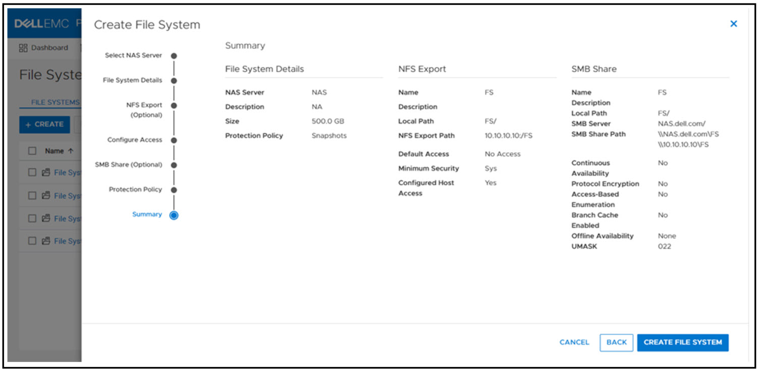
When the file system and NFS export or SMB share is provisioned, you now mount the file system on to your host for access:
- SMB: \\<SMB_Server>\<SMB_Share_Name>
- For example: \\nas\fs
- NFS: mount <NFS_Server>:/<NFS_Export_Name> /<Mountpoint>
- For example: mount nas:/fs /mnt
File system management
PowerStore file systems provide increased flexibility by providing the ability to shrink and extend file systems as needed. Shrink and extend operations are used to resize the file system and update the capacity that is seen by the client. Extend operations do not change how much capacity is allocated to the file system. However, shrink operations may be able to reclaim unused space, depending on how much capacity is allocated to the file system and the presence of snapshots or thin clones.
If the advertised file system size is too small or full, extending it allows additional data to be written to the file system. If the advertised file system size is too large, shrinking it limits the amount of data that can be written to the file system. For shrink and extend, the minimum value is equal to the used size of the file system; the maximum value is 256 TB. You cannot shrink the file system to less than the used size, because this would cause the client to see the file system as more than 100% full.
The following figure shows the file system properties page in PowerStore Manager, where you can shrink or extend a file system.
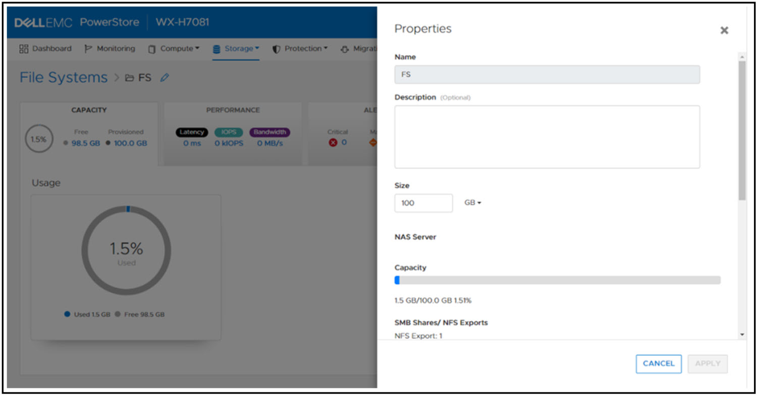
File system performance metrics
Performance metrics are available to view the latency, IOPS, bandwidth, and IO size at the file system level. You can tweak the timeline to view preset timeframes ranging from the last hour to the last 2 years, or drag and zoom in to specific sections of the graph. You can also export the metrics to file types such as PNG, PDF, JPEG, or CSV.
File-specific metrics are also available at the node, cluster, and appliance level. At the node level, SMB and NFS protocol metrics can also be viewed. The available metrics are:
- Read, Write, and Total IOPS
- Read, Write, and Total Bandwidth
- Read, Write, and Average Latency
- Read, Write, and Average IO Size
The following figure shows the file metrics page that displays the NFS protocol metrics on Node A.
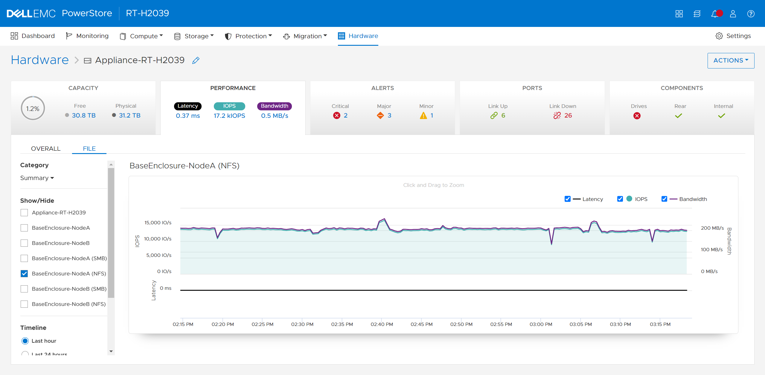
Conclusion
Congratulations! You have successfully provisioned a file system, NFS export, SMB share, and accessed it from a host. Now you can write files and folders or run workloads on the file system. We also reviewed how to leverage shrink and extend to update the file system size, and looked at some of the performance metrics so you can monitor your file systems. Stay tuned for the next blog in this series where we’ll take a deeper dive into the SMB protocol.
Resources
Author: Wei Chen, Senior Principal Engineering Technologist

Let’s Talk File (#2) – PowerStore NAS Servers
Wed, 20 Apr 2022 17:22:25 -0000
|Read Time: 0 minutes
Introduction
PowerStore file uses virtualized file servers that are called NAS servers, which are a critical piece of a file environment. In this blog, we will review what NAS servers are, study the NAS server architecture and its benefits, take a quick look at the NAS server settings, and walk through the process to create a new NAS server using PowerStore Manager.
What is a NAS server? A NAS server provides administrators with the ability to specify how PowerStore and its clients should connect, authenticate, and communicate with each other. It contains the configuration, interfaces, and environmental information that is used to facilitate access to the data residing on the file systems. In addition, features such as anti-virus protection, backups, user mappings, and more are also configured on the NAS server.
NAS Server Architecture
PowerStore’s modern NAS server architecture provides many inherent benefits. NAS servers have many responsibilities, including enabling access to file systems, providing data separation, and acting as a basis for multi-tenancy. They are also used as components for load balancing and high availability. This makes it quick and simple to deploy a feature-rich and enterprise-level file solution that meets your business requirements. The image below illustrates the NAS server architecture on PowerStore.
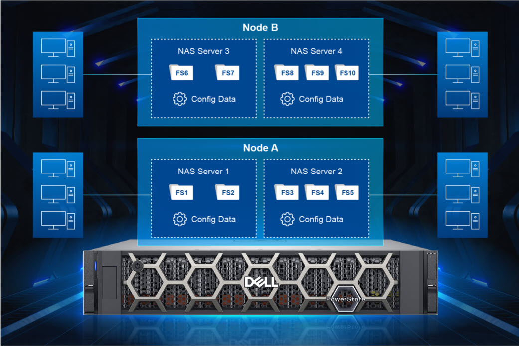
Each NAS server has its own independent configuration, enabling it to be used to enforce multitenancy. This is useful when hosting multiple tenants on a single system, such as for service providers. Each NAS server can be tailored to meet the requirements of each tenant without impacting the other NAS servers on the same appliance.
When creating a file system, the file system is assigned to a NAS server. Each NAS server has its own set of file systems to store file data. Because each NAS server is logically separated from the others, clients that have access to one NAS server do not inherently have access to the file systems on the other NAS servers. To access file systems on a different NAS server, clients must separately authenticate using the methods specified by that NAS server.
Each PowerStore node can host multiple NAS servers and both nodes are actively used to service file IO. New NAS servers are automatically assigned on a round-robin basis across both available nodes. This active/active architecture enables load balancing, provides high availability, and allows both nodes to serve file data simultaneously. If a PowerStore node reboots, NAS servers and their corresponding file systems automatically fail over to the surviving node. NAS servers are also automatically moved to the peer node and back during the upgrade process. After the upgrade completes, the NAS servers return to the node they were assigned to at the beginning of the upgrade.
NAS Server Settings
Let’s do a quick review of some of the items that can be configured on a NAS server. See the following table for a list of items along with a short description of their purpose.
Don’t worry if you’re not familiar with some of these services or terms because they’re not all required. You only need to enable and configure services that you are actively using in your specific environment. We’ll also cover these services in more detail in future blogs in this series.
Name | Description |
Interfaces | IP address, subnet, gateway, and VLAN to access the NAS server |
Access Protocols | Server Message Block (SMB) – Primarily used by Windows clients for SMB shares |
Network File System (NFS) – Primarily used by UNIX and VMware ESXi clients for NFS exports | |
File Transfer Protocol (FTP) – Used by all clients for file transfers | |
SSH File Transfer Protocol (SFTP) - Used by all clients for secure file transfers | |
Lightweight Directory Access Protocol (LDAP) / Network Information Service (NIS) / Local Files | Resolving user IDs and names to each other |
Domain Name System (DNS) | Resolving IP addresses and names to each other |
Anti-virus | Anti-virus servers used to identify and eliminate known viruses before they infect other files |
Network Data Management Protocol (NDMP) | A standard used for backing up file storage |
Kerberos | A distributed authentication service used for Secure NFS |
How to Configure a NAS Server
When deploying a file environment, the first resource you should provision on PowerStore is the NAS server. Now that you understand how they work, let’s go ahead and create one. To do this, open PowerStore Manager and navigate to Storage > NAS Servers. The NAS server creation wizard prompts you for the information displayed in the table below. All of these options can also be modified after creation, if needed.
Name | Description |
Interface Details (Required) |
|
Sharing Protocols (Optional) |
Note: If both SMB and NFS protocols are enabled, multiprotocol access is automatically enabled |
UNIX Directory Services (shown if NFS is enabled) |
|
DNS (Required for AD Joined SMB Servers, but otherwise optional) |
|
The screenshot below shows an example of the summary page when configuring a new NAS server. In this example, we created an interface, AD-joined SMB Server, NFSv3, and DNS.
If you’re testing file for the first time, you may want to start off with deploying a basic minimum configuration. To do this, all you need to configure is an interface and enable at least one access protocol.
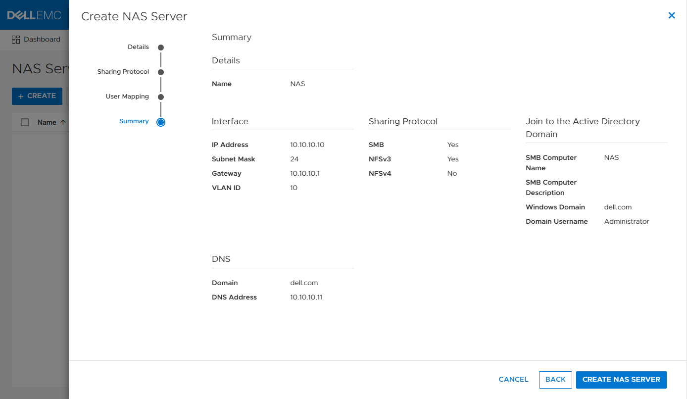
Conclusion
Now that we have our NAS server configured, our clients have a communication path to connect to PowerStore using a file protocol! This is the first major step, but we’re not done yet. Next, we need to provision a file system to store our data and shares or exports to make the file system accessible to clients. Stay tuned for the next blog in this series where we’ll review file system provisioning, management, and monitoring.
Resources
Author: Wei Chen, Senior Principal Engineering Technologist

What’s New in PowerStoreOS 2.1.1
Tue, 19 Apr 2022 10:00:08 -0000
|Read Time: 0 minutes
New releases continue to pile on for PowerStore, and today marks the most recent release with PowerStoreOS 2.1.1. This new release unlocks a lot of content for a service pack, but to fully understand what it delivers, we’ll need to revisit the previous release, PowerStoreOS 2.1.
PowerStoreOS 2.1 packed a lot into a minor release, including several key features on top of continued performance improvements and general enhancements. The anchor features were front-end NVMe/TCP access and integration with SmartFabric Storage Software. However, this release also included DC support for PowerStore 500, dynamic node affinity for improved storage intelligence, and various management, security and serviceability features.
The first service pack for PowerStoreOS 2.1, also known as PowerStoreOS 2.1.1, is supported on all PowerStore models, including PowerStore T and PowerStore X. If you recall, with the PowerStoreOS 2.1 launch in January, the new software was only made available to PowerStore T appliances. With this latest release, all software features introduced in PowerStoreOS 2.1 are now available on PowerStore X. Besides bringing the new set of features to PowerStore X, this release introduces several general system enhancements to both platforms, and specific improvements to PowerStore X models.
PowerStoreOS 2.1.1
PowerStoreOS 2.1.1 brings the features of PowerStoreOS 2.1 to PowerStore X appliances, plus some general system enhancements. Beyond the capabilities of PowerStoreOS 2.1, PowerStoreOS 2.1.1 also introduces vSphere 7 for PowerStore X, a brand new capability available in this latest release.
PowerStoreOS 2.1 for PowerStore X
Since PowerStoreOS 2.1.1 unlocks the new features of PowerStoreOS 2.1 on PowerStore X, it makes sense to recap those features here. The following features were all introduced in the previous release, and they are now fully supported on PowerStore X models:
NVMe/TCP: Support for host connectivity using NVMe over Ethernet fabrics with NVMe/TCP on existing embedded and IO module Ethernet ports.
- SmartFabric Storage Software (SFSS) support: A software product that enables an end-to-end automated and integrated NVMe/TCP fabric connecting NVMe hosts and targets.
- Dynamic node affinity: Dynamically-set node access when mapping volumes to hosts and the ability to automatically change node affinity for load balancing purposes.
- Customizable login message: Enables storage administrators to create, enable and disable a customizable login message.
- Application tags: Allows users to create application tags to label volumes for better organization and management.
- Thin packages and upgrades: Adds support for off-release packages such as hotfixes, disk firmware or improved health checks.
For more detail on the PowerStoreOS 2.1 release, make sure to check out the blog What’s New with the Dell PowerStoreOS 2.1 Release?.
vSphere 7 for PowerStore X
The jump from vSphere 6.7 to vSphere 7 delivers significant improvements to the ESXi nodes, which serve as the foundation of any PowerStore X cluster. A multitude of security enhancements ensure that your system has all the newest developments and improvements that were captured in vSphere 7.
Another change introduced in vSphere 7.0 is called vSphere Cluster Services (vCLS). This is a modification on how both vSphere DRS and vSphere HA are implemented for the ESXi cluster. This change ensures the continued functionality of vSphere DRS and vSphere HA in the event the vCenter Server instance becomes unavailable. Since both features are crucial to any PowerStore X cluster, this change will certainly be noticed by any observant virtualization administrator. Although hidden in the standard inventory view, the vCLS components appear as virtual machines when viewing the PowerStore vVol datastore.
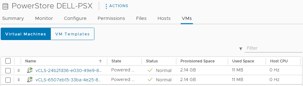
After you deploy a PowerStore X cluster running PowerStoreOS 2.1.1, you can confirm the vSphere version running on the hosts by selecting them directly in vSphere. Note that as additional updates are released for PowerStore, the exact version of vSphere may not match the version captured in the screenshot below. Make sure to reference the PowerStore Simple Support Matrix to get the most up-to-date information on supported versions. 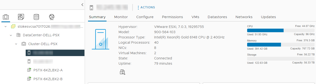
In addition to vSphere, PowerStore Manager also captures this information. From the Dashboard page, simply navigate to Compute > Hosts & Host Groups and note the ESXi Version column. This column is not enabled by default and must be added using the Show/Hide Columns option to the right of the table.
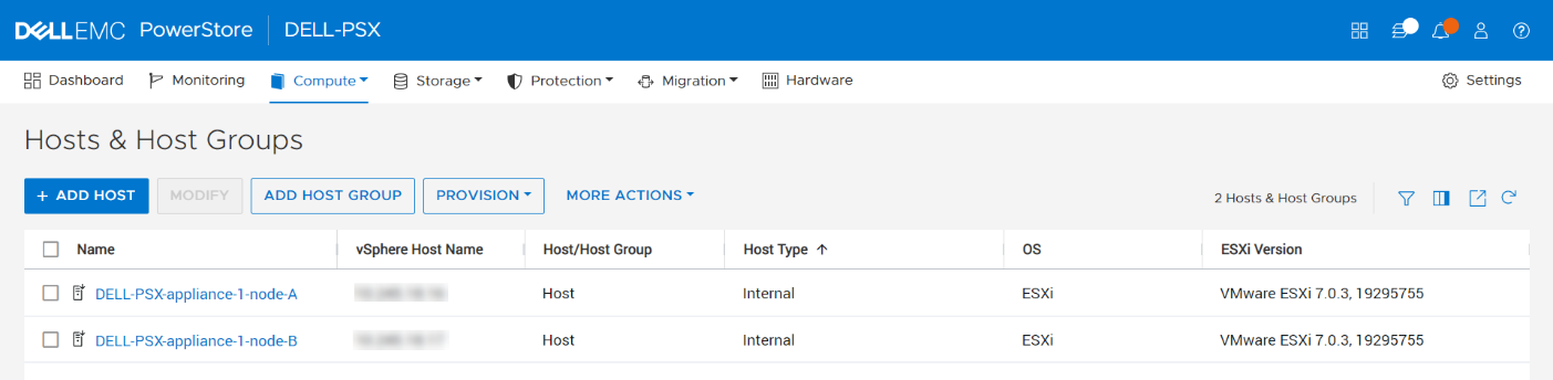
Upgrading to PowerStoreOS 2.1.1
All these new features sound great, but the next logical question is: How do I get this code running on my system? Thankfully, PowerStore fully supports a non-disruptive upgrade (NDU) to PowerStoreOS 2.1.1 on both PowerStore T and PowerStore X appliances.
PowerStore T upgrades
While much of the new content in PowerStoreOS 2.1.1 is directed toward PowerStore X systems, there are still several general system enhancements and bug fixes that will benefit PowerStore T appliances. PowerStore T upgrades are fully supported on systems running PowerStoreOS 1.X or 2.X. Make sure to download the latest version of the PowerStore Release Notes to determine which software upgrade packages are required based on the current version of code you are running. For all PowerStore upgrades, see the Dell EMC PowerStore Software Upgrade Guide on dell.com/powerstoredocs.
PowerStore X upgrades
PowerStoreOS 2.1.1 upgrades are fully supported on PowerStore X clusters running PowerStoreOS 2.0.X. If the cluster is running an earlier version, you can first perform an upgrade to PowerStoreOS 2.0.X. Once that is satisfied, ensure that the vCenter Server connected to the PowerStore X cluster is running a supported version of vSphere 7.0. To view the current list of supported vCenter Server versions, see the VMware Licensing and Support for PowerStore X table in the PowerStore Simple Support Matrix. Finally, make sure to see the Dell EMC PowerStore Software Upgrade Guide on dell.com/powerstoredocs.
Conclusion
The PowerStoreOS 2.1.1 release provides new capabilities to PowerStore X systems, unlocking NVMe/TCP, SmartFabric Storage Software support, vSphere 7, dynamic node affinity, and much more. Adding to these new features, several system enhancements and bug fixes are delivered for both PowerStore X and PowerStore T model appliances. With easy, non-disruptive upgrade options for all PowerStore models, this is a great release for any currently deployed system.
Resources
- Dell PowerStore: Technical Primer
- What’s New with the Dell PowerStoreOS 2.1 Release?
- PowerStore Simple Support Matrix
- Dell.com/powerstoredocs
Author
Ethan Stokes, Senior Engineering Technologist

Have You Checked Your Snapshots Lately?
Mon, 28 Mar 2022 21:44:38 -0000
|Read Time: 0 minutes
While this question may sound like a line from a scary movie, it is a serious one. Have you checked your snapshots lately?
In many regions of the world, seasonal time changes occur to maximize daylight hours and ensure darkness falls later in the day. This time shift is commonly known as Daylight Time, Daylight Saving Time, or Summer Time. Regions that observe this practice often change their clocks by 30 minutes or 1 hour depending on the region and time of year. At the time of this publication, multiple regions of the world have recently experienced a time change, while others occur shortly after this publication.
Some storage systems use Coordinated Universal Time (UTC) internally for logging purposes and to run scheduled jobs. Users typically create a schedule to run a task based on their local time, but the storage system then adjusts this time and runs the job based on the internal UTC time. When a regional change in time occurs, scheduled tasks that run on a UTC schedule “shift” when compared to wall clock time. Something that used to run at one time locally may seem to run at another, but only because the wall clock time in the region has changed. While this shift in schedule may not be an issue to most, with some customers the change is noticeable. Some have found that jobs such as snapshot creations and deletions are now occurring during other scheduled tasks such as backups or the snapshots are now missing the intended time, such as the beginning or end of the business workday.
To show what I mean, let’s use the Eastern US time zone as an example. Let’s say a user has created a rule to take a snapshot daily at 12:00 AM midnight local time. When Daylight Saving Time is not in observance, 12:00 AM US EST is equivalent to 5:00 AM UTC and the snapshot schedule will be configured to run at 5:00 AM UTC daily within the system. On Sunday, March 13, 2022 at 2:00 AM the regions of the United States that observe time changes altered their clocks 1 hour forward. The 2:00 AM hour instantaneously became 3:00 AM and an hour of time was seemingly lost.
As the figure below shows, a scheduled job that is configured to run at 5:00 AM UTC daily was taking snapshots at 12:00 AM local time but now runs at 1:00 AM local time, due to the UTC schedule of the storage system and the time change. A similar shift also occurs when the time change occurs again later in the year.
Within PowerStore, protection policies, snapshot rules, and replication rules are used to apply data protection to a resource. A snapshot rule is created to tell the system when to create a snapshot on a resource. The snapshot rule is then added to a protection policy, and the protection policy is assigned to a resource. When creating a snapshot rule, the user can either choose a fixed interval based on several hours or provide a specific time to create a snapshot.
For systems running PowerStoreOS 2.0 or later, when specifying the exact time to create a snapshot, the user also selects a time zone. The time zone drop-down list defaults to the user’s local time zone, but it can be adjusted if the system is physically located in a different time zone. Specifying a specific time with a time zone ensures that seasonal time changes do not impact the creation time of a snapshot.
For systems that were configured with a code prior to the 2.0 release and later upgraded, it is a great idea to review the snapshot rules and ensure that ones that are configured for a particular time of day are set correctly.
So, I ask again: Have you checked your snapshots lately?
Resources
Technical Documentation
- To learn more about the different features that PowerStore provides, see the PowerStore Info Hub.
- For additional information about PowerStore snapshots, see the PowerStore: Snapshots and Thin Clones white paper.
Demos and Hands-on Labs
- To see how PowerStore’s features work and integrate with different applications, see the PowerStore Demos YouTube playlist.
- To gain firsthand experience with PowerStore, see our many Hands-On Labs.
Author: Ryan Poulin

Let’s Talk File (#1) – PowerStore File Overview
Mon, 21 Mar 2022 14:15:46 -0000
|Read Time: 0 minutes
Introduction
Our customers have a wide variety of traditional and modern workloads. Each of these workloads connects to the underlying infrastructure using various networking protocols. PowerStore’s single architecture for block, file, and vVols uses the latest technologies to achieve these disparate objectives without sacrificing the cost-effective nature of midrange storage. PowerStore provides the ultimate workload flexibility and enables IT to simplify and consolidate infrastructure.
PowerStore features a native file solution that is highly scalable, efficient, performance-focused, and flexible. In this new series, we’ll visit the vast world of PowerStore file and review the comprehensive set of features that it offers. Over the course of this series, we’ll cover everything from NAS servers, file systems, quotas, snapshots and thin clones, protocols, multiprotocol, directory services, and more. We’ll start with the basics before diving in deeper, so no previous file experience or knowledge is required!
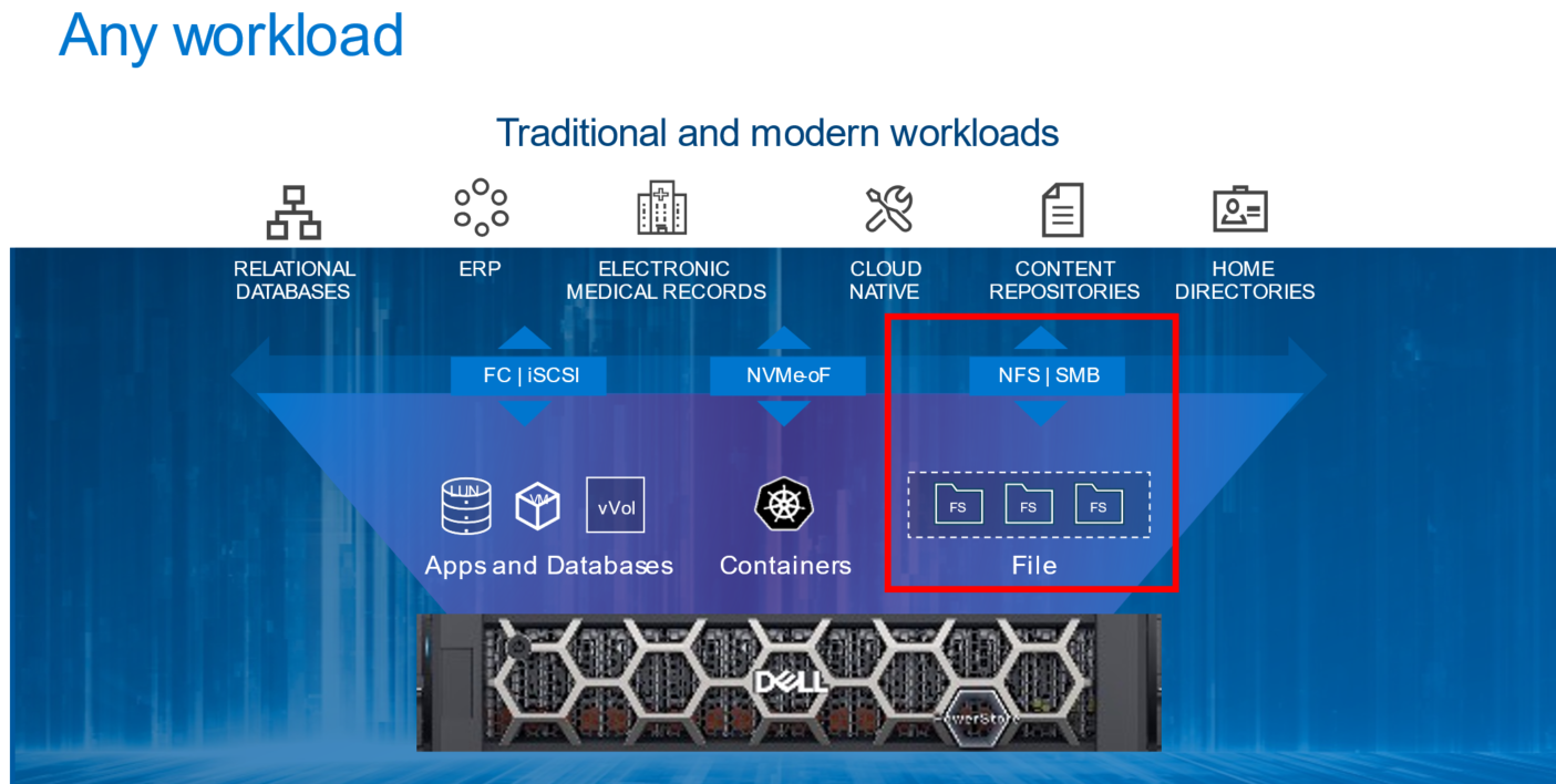
File Overview
Let’s start with a quick and high-level overview of file. File-level storage is a storage type where files are shared across a network to a group of heterogeneous clients. It is also known as Network-Attached Storage (NAS). File-level storage is widely used across small and medium-sized businesses to large enterprises across the world. If you’ve ever connected to a shared drive such as a home directory or departmental share, then you’ve used file-level storage before.
PowerStore File
File functionality is natively available on PowerStore T model appliances that are configured in Unified mode. There are no extra pieces of software, hardware, or licenses required to enable this functionality. All file management, monitoring, and provisioning capabilities are available in the HTML5-based PowerStore Manager.
Within an appliance, both nodes are used for both file as well as block. This configuration creates a fully redundant and active/active architecture where both nodes are used to serve file data simultaneously. This design provides the ability to load balance across both nodes while also ensuring high availability.
PowerStore supports the following file access protocols:
- Server Message Block (SMB) – Primarily used by Windows clients for SMB shares
- Network File System (NFS) – Primarily used by UNIX clients for NFS exports
- File Transfer Protocol (FTP) – Used by all clients for file transfers
- SSH File Transfer Protocol (SFTP) – Used by all clients for secure file transfers
PowerStore File Systems
PowerStore features a 64-bit file system architecture that is designed to be highly scalable, efficient, performant, and flexible. PowerStore also includes a rich supporting file feature set to ensure that the data is secure, protected, and can be easily monitored.
PowerStore file systems are also tuned and optimized for high performance. In addition, platform components such as Non-Volatile Memory Express (NVMe) drives and dual-socket CPUs enable the system to maintain low response times while servicing large workloads.
The maturity and robustness of the PowerStore file system combined with these supporting features enables it to be used in many file-level storage use cases, such as departmental shares or home directories.
Conclusion
With the native file capabilities available on PowerStore, administrators can easily implement a file solution that is designed for the modern data center. Throughout this blog series, we’ll review how quick and easy it is to configure file in your data center.
Now that we have an overview of file, we can begin jumping into more specific technical details. Stay tuned for the next blog in this series where we’ll start by looking at NAS servers and their role in facilitating access to the data residing on the file systems.
Resources
Author: Wei Chen, Senior Principal Engineering Technologist

What’s New with the Dell PowerStoreOS 2.1 Release?
Tue, 15 Mar 2022 21:40:19 -0000
|Read Time: 0 minutes
2022 got off to a great start with the PowerStoreOS 2.1 release. It builds upon the previous release with performance improvements and added functionality to support current and future workloads. PowerStoreOS 2.1 provides these key features:
- NVMe/TCP – This protocol, based on standard IP over Ethernet networks, allows users to take advantage of their existing network for storage. NVMe/TCP is much more efficient, parallel, and scalable than SCSI. It makes an external networked array feel like direct attach storage. PowerStoreOS 2.1 introduced support for NVMe/TCP on PowerStore appliances, which allows users to configure Ethernet interfaces for iSCSI or NVMe/TCP host connectivity.
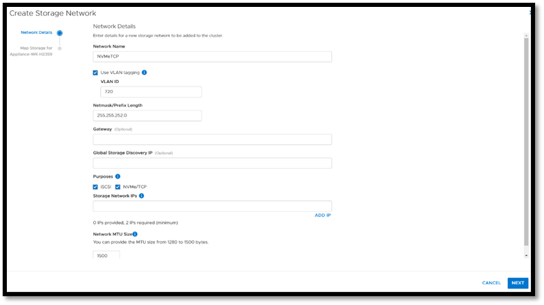
- SmartFabric Storage Software integration – (SFSS) is a new and innovative software product from Dell Technologies that enables an end-to-end automated and integrated NVMe/oF Ethernet fabric connecting NVMe hosts and targets using TCP. The solution was designed in partnership with VMware and provides enterprise organizations with the agility to stay ahead of growing workload demands. It supports modern, automated, and secure storage connectivity both today and for future hybrid cloud migrations.
- Dynamic Node Affinity – This feature allows PowerStore to dynamically set a node for access when mapping volumes to a host, and allows it to automatically change the node affinity for load balancing purposes.
- DC support with PowerStore 500 – Allows users to utilize DC power supply units instead of just AC with their storage appliance.
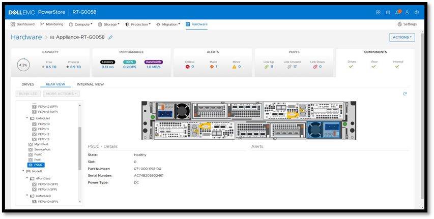
- Management and Serviceability
- Customizable Login Message – Enables storage administrators to create, enable, and disable a customizable login message.
- Application Tags – Allows users to specify a volume application tag during volume creation. This allows labeling of the volumes with a specific category and application type, based on the use case. Using application-centric management, users can view and sort through volumes by the application tag, by adding the new “Application” column in the list view.
- Thin Packages and Upgrades – In PowerStore Manager you can manage, upload, and deploy various non-disruptive upgrade (NDU) packages. Generally, the NDU packages consist of two categories: software releases and thin packages. Software releases are PowerStoreOS upgrades that contain the full operating-system (OS) image, or patch or hotfix images, for a specific OS version. Thin packages contain a smaller and more targeted amount of functionality than regular PowerStoreOS packages. These allow Dell to offer off-release updates such as hotfixes, disk firmware, pre-upgrade health check updates, and usually do not require node reboots. Thin packages are what is new with the 2.1 release and since they’re typically smaller in size, it saves users time and effort during the install process.
- Telemetry Notices – There is a notification displayed after the EULA which provides information about the Dell Telemetry collector and privacy policy information.
Check out the information below about this jampacked release: white papers, videos, and an interactive demo. The Dell Info Hub has a wealth of great material and we hope it helps you with your innovative technology solutions!
Resources
Documentation
- Dell Technologies Info Hub
- Dell PowerStore Info Hub Page
- Dell PowerStore: Technical Primer
- Dell PowerStore: Introduction to the Platform
- Dell PowerStore: PowerStore Manager Overview
- Dell PowerStore: Virtualization Integration
- Dell PowerStore: Clustering and High Availability
- Dell PowerStore: Best Practices
- SmartFabric Storage Software Deployment Guide
Videos
- SmartFabric Storage Software (SFSS)
Interactive Demo
Author: Andrew Sirpis, Senior Principal Engineering Technologist

PowerStore REST API: Using Filtering to Fine Tune Your Queries
Fri, 11 Mar 2022 16:03:19 -0000
|Read Time: 0 minutes
The PowerStore REST API provides a powerful way to manage a PowerStore cluster, mainly when using one’s own scripts [3] or automation tools.
In some areas of PowerStore, almost all of its functionality is available when using the REST API – and sometimes even more when the required attributes are unavailable in the PowerStore Manager GUI.
A great place to start learning more about the REST API is the integrated SwaggerUI [2] which provides online documentation with test functionality on your system. SwaggerUI uses an OpenAPI definition. Some 3rd party tools can leverage the same OpenAPI definition, and can be downloaded from SwaggerUI. SwaggerUI is available on all PowerStore models and types by using https://<PowerStore>/swaggerui in your preferred browser.
When working with the PowerStore REST API it’s not always obvious how to query some attributes. For example, it’s easy to filter for a specific volume name to get id, size, and type of a volume or volumes when using “*” as wildcard:
To query for all volumes with “Test” somewhere in its name, we could use
name=like.*Test*
as the query string:
% curl -k -s -u user:pass -X GET "https://powerstore.lab/api/rest/volume?select=id,name,size,type&name=like.*Test*" | jq .
[
  {
    "id": "a6fa6b1c-2cf6-4959-a632-f8405abc10ed",
    "name": "TestVolume",
    "size": 107374182400,
    "type": "Primary"
  }
]
In that example, although we know that there are multiple snapshots for a particular volume, the REST API query that uses the parent volume name does not show the related snapshots. It’s because snapshots must not have the name of the parent volume in their name. From PowerStore Manager we know that this volume has three snapshots, but their names do not relate to the volume name: 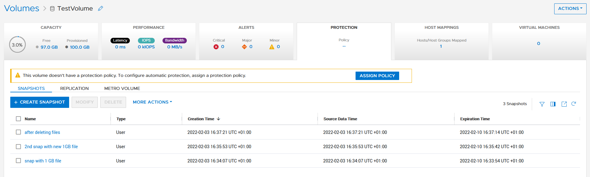
How is it possible to get the same output with a REST API query? We know that everything in PowerStore is managed with IDs, and the API description in SwaggerUI shows that a volume could have an attribute parent_id underneath the protection_data section.
All volumes with a protection_data->>parent_id that is equal to the ID of our “TestVolume” show the related snapshots for the TestVolume. The key for the query is the following syntax for the underlying attributes:
protection_data->>parent_id=eq.a6fa6b1c-2cf6-4959-a632-f8405abc10ed
The resulting curl command to query for the snapshot volumes shows the same syntax to select “creator_type” from a nested resource:
% curl -k -s -u user:pass -X GET 'https://powerstore/api/rest/volume?select=id,name,protection_data->>creator_type,creation_timestamp&protection_data->>parent_id=eq.a6fa6b1c-2cf6-4959-a632-f8405abc10ed' | jq .
[
  {
    "id": "051ef888-a815-4be7-a2fb-a39c20ee5e43",
    "name": "2nd snap with new 1GB file",
     "creator_type": "User",
"creation_timestamp": "2022-02-03T15:35:53.920133+00:00"
},
{
"id": "23a26cb6-a806-48e9-9525-a2fb8acf2fcf",
"name": "snap with 1 GB file",
"creator_type": "User",
"creation_timestamp": "2022-02-03T15:34:07.891755+00:00"
},
{
"id": "ef30b14e-daf8-4ef8-8079-70de6ebdb628",
"name": "after deleting files",
"creator_type": "User",
"creation_timestamp": "2022-02-03T15:37:21.189443+00:00"
}
]Resources
For more white papers, blogs, and other resources about PowerStore, please visit our PowerStore Info Hub.
Related resources to this blog on the Info Hub:
- For a general PowerStore Manager overview, see Dell PowerStore Manager Overview
- To learn more about volumes and volume families: PowerStore: Snapshots and Thin Clones
- An alternative to REST API: What is PowerStoreCLI Filtering?
For some great video resources referenced in this blog, see:
- [1] Dell PowerStore REST API Part 1 - Introduction
- [2] Dell PowerStore REST API Part 2 - PowerStore SwaggerUI
- [3] Dell PowerStore REST API Part 3 - Python script example
See also this PowerStore product documentation:
Author: Robert Weilhammer, Principal Engineering Technologist

Exploring Amazon EKS Anywhere on PowerStore X – Part I
Wed, 19 Jan 2022 15:17:00 -0000
|Read Time: 0 minutes
A number of years ago, I began hearing about containers and containerized applications. Kiosks started popping up at VMworld showcasing fun and interesting uses cases, as well as practical uses of containerized applications. A short time later, my perception was that focus had shifted from containers to container orchestration and management or simply put, Kubernetes. I got my first real hands on experience with Kubernetes about 18 months ago when I got heavily involved with VMware’s Project Pacific and vSphere with Tanzu. The learning experience was great and it ultimately lead to authoring a technical white paper titled Dell EMC PowerStore and VMware vSphere with Tanzu and TKG Clusters.
Just recently, a Product Manager made me aware of a newly released Kubernetes distribution worth checking out: Amazon Elastic Kubernetes Service Anywhere (Amazon EKS). Amazon EKS Anywhere was preannounced at AWS re:Invent 2020 and announced as generally available in September 2021.
Amazon EKS Anywhere is a deployment option for Amazon EKS that enables customers to stand up Kubernetes clusters on-premises using VMware vSphere 7+ as the platform (bare metal platform support is planned for later this year). Aside from a vSphere integrated control plane and running vSphere native pods, the Amazon EKS Anywhere approach felt similar to the work I performed with vSphere with Tanzu. Control plane nodes and worker nodes are deployed to vSphere infrastructure and consume native storage made available by a vSphere administrator. Storage can be block, file, vVol, vSAN, or any combination of these. Just like vSphere with Tanzu, storage consumption, including persistent volumes and persistent volume claims, is made easy by leveraging the Cloud Native Storage (CNS) feature in vCenter Server (released in vSphere 6.7 Update 3). No CSI driver installation necessary.
Amazon EKS users will immediately gravitate towards the consistent AWS management experience in Amazon EKS Anywhere. vSphere administrators will enjoy the ease of deployment and integration with vSphere infrastructure that they already have on-premises. To add to that, Amazon EKS Anywhere is Open Source. It can be downloaded and fully deployed without software or license purchase. You don’t even need an AWS account.
I found PowerStore was a good fit for vSphere with Tanzu, especially the PowerStore X model, which has a built in vSphere hypervisor, allowing customers to run applications directly on the same appliance through a feature known as AppsON.
The question that quickly surfaces is: What about Amazon EKS Anywhere on PowerStore X on-premises or as an Edge use case? It’s a definite possibility. Amazon EKS Anywhere has already been validated on VxRail. The AppsON deployment option in PowerStore 2.1 offers vSphere 7 Update 3 compute nodes connected by a vSphere Distributed Switch out of the box, plus support for both vVol and block storage. CNS will enable DevOps teams to consume vVol storage on a storage policy basis for their containerized applications, which is great for PowerStore because it boasts one of the most efficient vVol implementations on the market today. The native PowerStore CSI driver is also available as a deployment option. What about sizing and scale? Amazon EKS Anywhere deploys on a single PowerStore X appliance consisting of two nodes but can be scaled across four clustered PowerStore X appliances for a total of eight nodes.
As is often the case, I went to the lab and set up a proof of concept environment consisting of Amazon EKS Anywhere running on PowerStore X 2.1 infrastructure. In short, the deployment was wildly successful. I was up and running popular containerized demo applications in a relatively short amount of time. In Part II of this series, I will go deeper into the technical side, sharing some of the steps I followed to deploy Amazon EKS Anywhere on PowerStore X.
Author: Jason Boche
Twitter: (@jasonboche)

Part 2 – The ‘What’ - Introducing Dell Container Storage Modules (CSM)

Fri, 19 Nov 2021 14:17:13 -0000
|Read Time: 0 minutes
In the first post of the series, which you can read all about here, I discussed some of the challenges that are associated with managing the storage / Data Protection aspects of Kubernetes. Now, let’s discuss our solutions:
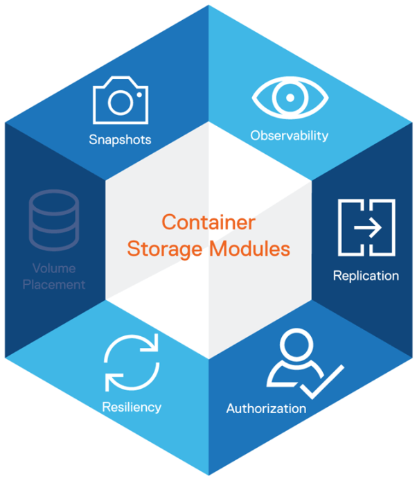
Enter CSM, or Introduction to Container Storage Modules
Remember the 2019 session and the in-depth thinking we had gone through about our customers’ real world needs? The Kubernetes ecosystem is growing rapidly and when it comes to storage integration, CSI plugins offer a way to expose block and file storage systems to containerized workloads on Container Orchestration systems (COs) like Kubernetes.
Container Storage Modules (CSM) improves the observability, usability, and data mobility for stateful applications using Dell Technologies storage portfolio. It also extends Kubernetes storage features beyond what is available in the Container Storage Interface (CSI) specification. CSM and the underlying CSI plugins are pioneering application-aware/application consistent backup and recovery solutions from the most comprehensive enterprise-grade storage and data protection for Kubernetes.
CSM extends enterprise storage capabilities to Kubernetes. It reduces management complexity so developers can independently consume enterprise storage with ease and automate daily operations such as provisioning, snapshotting, replication, observability, authorization, and resiliency. CSM is open-source and freely available from https://github.com/dell/csm.
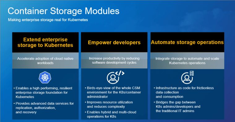
Dell EMC Container Storage Modules (CSM) brings powerful enterprise storage features and functionality to Kubernetes for easier adoption of cloud-native workloads, improved productivity, and scalable operations. This release delivers software modules for storage management that provide developers with access to build automation for enhanced IT needs and other critical enterprise storage features. These include data replication across data centers, role-based access control (RBAC) authorization, observability, and resiliency for disaster recovery and avoidance. Improved resource utilization enables automated access to any of our portfolio storage systems into K8s environments and:
- Gives the flexibility to choose whatever in the back end allows them to provision and leverage the strengths of the individual system
- Flexible + simple = powerful
- You have storage that isn’t 100% utilized
This enables the K8 environment manager to directly allocate storage and services, and it:
- Reduces time
- Gives them the pot to pull things out of and then lets them go handle it
- Frees up the developer to develop
Extend Enterprise Storage to Kubernetes – by accelerating adoption of cloud-native workloads with proven enterprise storage with proven enterprise storage:
- Dell EMC Container Storage Modules (CSM) enables a high-performing and resilient enterprise storage foundation for Kubernetes.
- CSM delivers a full stack of enterprise capabilities such as industry-leading replication, authorization, failure recovery, and management. These capabilities accelerate deployment testing, resulting in a faster application deployment life cycle.
- CSM allows developers and storage admins to take advantage of the unique benefits of Dell EMC storage systems, such as PowerMax Metro smart DR and the PowerFlex software-defined storage architecture.
- Dell Technologies has purpose-built platforms for streaming data, IoT, and Edge computing use cases designed with container-based architecture and management. These capabilities accelerate deployment testing, resulting in a faster application deployment life cycle.
Empower Developers – Improve productivity by reducing development life cycles
- CSM reduces storage management complexity with observability modules so developers can consume enterprise storage with ease.
- It also provides a complete K8s solution stack that delivers an integrated experience for developers and storage admins.
- Customers will be able to take advantage of consistent monitoring, management, and policy enforcement across enterprise storage and DevOps environments.
Automate storage operations – Integrate enterprise storage with existing Kubernetes toolsets for scalable operations
- CSM allows customers to realize the promise of infrastructure as code for frictionless data collection and consumption
- CSM observability empowers customers to create storage pools across multiple storage arrays for minimal storage management
- CSM delivers an integrated experience that bridges the gap between Kubernetes admins/developers and the traditional IT admins, furthering solidifying enterprise storage’s role as a viable alternative to public cloud while eliminating silos and shadow IT.

The modules are separated into these six specific capabilities:
Observability – Delivers a single pane to view the whole CSM environment for the K8s/container administrator, using Grafana and Prometheus dashboards that K8s admins are familiar with in monitoring persistent storage performance.
Replication – Enables array replication capabilities to K8s users with support for stretched and replica K8s clusters.
Authorization – Provides storage and provides Kubernetes administrators the ability to apply RBAC and usage rules for our CSI Drivers.
Resiliency – Enables K8s node failover by monitoring persistent volume health, designed to make Kubernetes Applications, including those that use persistent storage, more resilient to node failures. The module is focused on detecting node failures (power failure), K8s control plane network failures, and Array I/O network failures, and to move the protected pods to hardware that is functioning correctly.
Volume Placement – Intelligent volume placement for Kubernetes workloads, optimized based on available capacity.
Snapshots - CSI based snapshots for operational recovery and data repurposing. The Snapshots feature is part of the CSI plugins of the different Dell EMC arrays and takes advantage of the state-of-the-art snapshot technology to protect and repurpose data. In addition to point-in-time recovery, these snapshots are writable and can be mounted for test and dev and analytics use cases without impacting the production volumes. These modules are planned for RTS, but there is a rolling release prioritized based upon customer demand by storage platform – applicable to PowerScale, PowerStore, PowerMax, PowerFlex, and Unity XT. Available on RTS:
- Authorization Module
- PowerScale
- PowerMax
- PowerFlex
- Resiliency Module
- PowerFlex
- Unity XT
- Observability Module
- PowerFlex
- PowerStore
- Replication Module
- PowerMax Metro/Async
- One Installer
The publicly accessible repository for CSM is available at https://github.com/dell/csm. For a complete set of material on CSM, see the documentation at https://dell.github.io/csm-docs/.
Here is an overview demo of CSM:
Watched it? Awesome, now let’s go deeper into the modules:
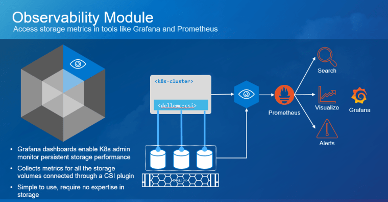
Observability
CSM for Observability is part of the CSM (Container Storage Modules) open-source suite of Kubernetes storage enablers for Dell EMC products. It is an OpenTelemetry agent that collects array-level metrics for Dell EMC storage so they can be scraped into a Prometheus database. With CSM for Observability, you will gain visibility not only on the capacity of the volumes/file shares you manage with Dell CSM CSI (Container Storage Interface) drivers but also their performance in terms of bandwidth, IOPS, and response time. Thanks to pre-packaged Grafana dashboards, you will be able to go through these metrics’ history and see the topology between a Kubernetes PV (Persistent Volume) and its translation as a LUN or file share in the backend array. This module also allows Kubernetes admins to collect array level metrics to check the overall capacity and performance directly from the Prometheus/Grafana tools rather than interfacing directly with the storage system itself. Metrics data is collected and pushed to the OpenTelemetry Collector, so it can be processed and exported in a format consumable by Prometheus.
CSM for Observability currently supports PowerFlex and PowerStore. Its key high-level features are:
- Collect and expose Volume Metrics via the OpenTelemetry Collector
- Collect and expose File System Metrics via the OpenTelemetry Collector
- Collect and expose export (K8s) node metrics via the OpenTelemetry Collector
- Collect and expose filesystem capacity metrics via the OpenTelemetry Collector
- Collect and expose block storage capacity metrics via the OpenTelemetry Collector
- Non-disruptive config changes
- Non-disruptive log level changes
- Grafana Dashboards for displaying metrics and topology data
Below, you can see the module, working with PowerStore:
And PowerFlex:
The publicly accessible repository is available at https://github.com/dell/csm-observability.
See documentation for a complete set of material on CSM Observability: https://dell.github.io/csm-docs/docs/observability/.
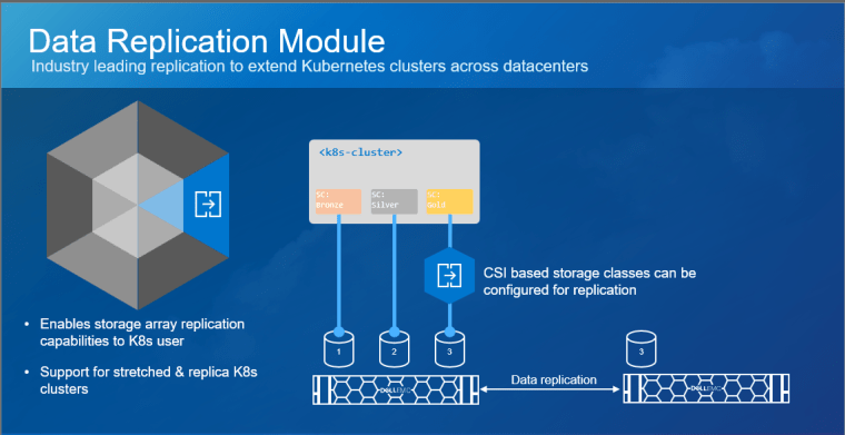
Replication
CSM for Replication is the module that allows provisioning of replicated volumes using Dell storage. CSM for Replication currently supports PowerMax and PowerStore.
Key High-Level Features:
- Replication of PersistentVolumes (PV) across Kubernetes clusters Multi/single cluster topologies
- Replication action execution (planned/unplanned failover, sync, pause, resume)
- Async/Sync/Metro configurations support (PowerStore only supports Async)
- repctl – CLI tool that helps with replication related procedures across multiple K8s clusters
The publicly accessible repository for CSM is available at https://github.com/dell/csm-replication.
See the documentation for a complete set of material on CSM Replication: https://dell.github.io/csm-docs/docs/replication/.
The following video includes an Introduction and the Architecture (using PowerMax as the example):
Below, you can see end-to-end demos on how to configure CSM replication for PowerStore, and how to perform failover & failback operations of WordPress and MySQL DB, using PowerStore Async replication.
Installing:
Performing Failover & Failback (Reprotect):
Using PowerMax?
- The following video shows synchronous replication using CSM Replication for PowerMax SRDF Sync Replication with File I/O being generated.
- This video shows Active-Active High-Availability using CSM Replication for PowerMax SRDF Metro Volumes with PostgreSQL:
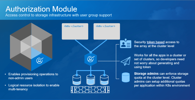
Authorization
- CSM for Authorization is part of the CSM (Container Storage Modules) open-source suite of Kubernetes storage enablers for Dell EMC products. CSM for Authorization provides storage and Kubernetes administrators the ability to apply RBAC for CSI Drivers. It does this by deploying a proxy between the CSI driver and the storage system to enforce role-based access and usage rules.
- Storage administrators of compatible storage platforms will be able to apply quota and RBAC rules that instantly and automatically restrict cluster tenants’ usage of storage resources. Users of storage through CSM for Authorization do not need to have storage admin root credentials to access the storage system.
- Kubernetes administrators will have an interface to create, delete, and manage roles/groups to which storage rules may be applied. Administrators and/or users can then generate authentication tokens that can be used by tenants to use storage with proper access policies being automatically enforced.
- CSM for Authorization currently supports PowerFlex, PowerMax, and PowerScale.
Its key high-level features are:
- Ability to set storage quota limits to ensure K8s tenants are not over consuming storage
- Ability to create access control policies to ensure K8s tenant clusters are not accessing storage that does not belong to them
- Ability to shield storage credentials from Kubernetes administrators, ensuring that credentials are only handled by storage admins
The publicly accessible repository is available at https://github.com/dell/csm-authorization.
See the documentation for a complete set of material on CSM Authorization: https://dell.github.io/csm-docs/docs/authorization/.
Below, you can see the Authorization module for PowerFlex:
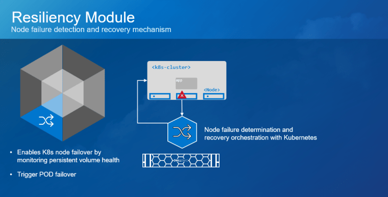
Resiliency
User applications can have problems if you want their Pods to be resilient to node failure. This is especially true of those deployed with StatefulSets that use PersistentVolumeClaims. Kubernetes guarantees that there will never be two copies of the same StatefulSet Pod running at the same time and accessing storage. Therefore, it does not clean up StatefulSet Pods if the node executing them fails.
CSM for Resiliency currently supports PowerFlex and Unity.
Key High-Level Features:
- Detect pod failures for the following failure types – Node failure, K8s Control Plane Network failure, Array I/O Network failure
- Cleanup pod artifacts from failed nodes
- Revoke PV access from failed nodes
Below, you can see a demo of the Resiliency module for PowerFlex:
The publicly accessible repo is available at https://github.com/dell/karavi-authorization.
See the documentation for a complete set of material on CSM Resiliency: https://dell.github.io/csm-docs/docs/authorization/.
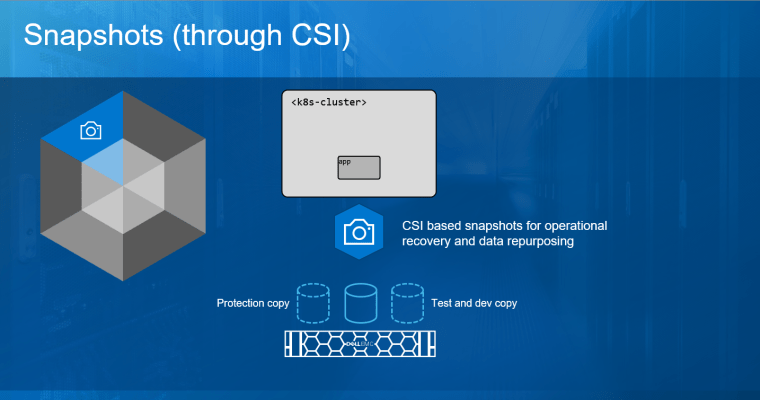
The Snapshots feature is part of the CSI plugins of the different Dell EMC arrays and takes advantage of the state-of-the-art snapshot technology to protect and repurpose data. In addition to point-in-time recovery, these snapshots are writable and can be mounted for test and dev and analytics use cases without impacting the production volumes.
See the following demo about volume groups snapshots for PowerFlex:
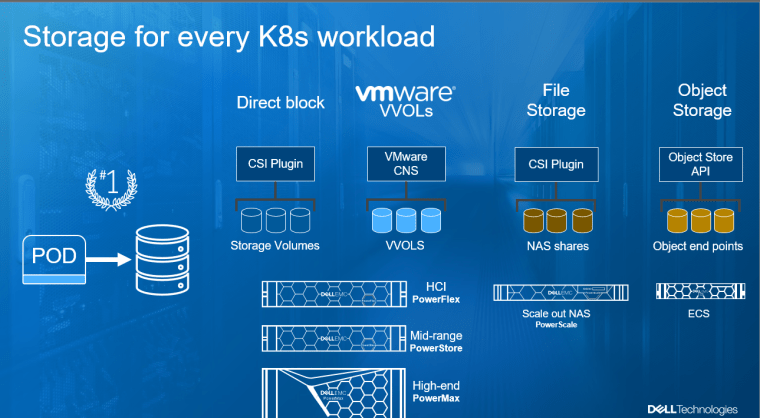
No man (or a customer) is an island and Kubernetes comes in many flavors. Here at Dell Technologies, we offer a wide variety of solutions for the customer, starting from just storage arrays for every need (from PowerStore to PowerFlex to PowerMax to PowerScale and ECS) to turnkey solutions like VxRail with/without VCF, deep integration with our storage arrays to anything from upstream Kubernetes to RedHat Openshift, with deep integration to the OpenShift Operator, or vSphere with Tanzu, just so we can meet you where you are today AND tomorrow.
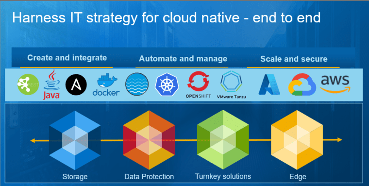
With Dell Technologies’ broad portfolio designed for modern and flexible IT growth, customers can employ end-to-end storage, data protection, compute, and open networking solutions that support rapid container adoption. Developers can create and integrate modern data applications by relying on accessible open-source integrated frameworks and tools across bare metal, virtual, and containerized platforms. Dell enables support for organizational autonomy and real-time benefits for container and Kubernetes platforms with and adherence to IT best practices based on an organization’s own design needs.
In the next post, we will be covering the ‘How’ to install the new CSI 2.0 Common installer and the CSM modules.
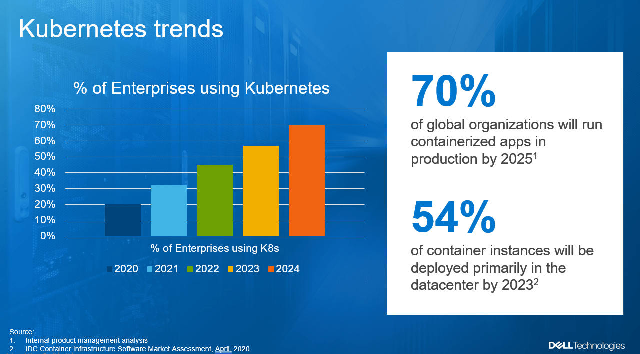
Introducing Dell Container Storage Modules (CSM), Part 1 - The 'Why'
Fri, 19 Nov 2021 14:17:13 -0000
|Read Time: 0 minutes
Dell Tech World 2019, yea, the days of actual in-person conferences, Michael Dell is on stage and during his keynote, he says “we are fully embracing Kubernetes”. My session is the next one where I explain our upcoming integration of storage arrays with the Kubernetes CSI (Container Storage Interface) API. Now, don’t get me wrong, CSI is awesome! But at the end of my session, I’m getting a lot of people coming to me and ask very similar questions, the theme was around ‘how do I still keeping track of what’s going to happen in the storage array’, you see, CSI doesn’t have role-based access to the storage array, not to even mention things like quota management. At a very high level, think about storage admins that want to embrace Kubernetes but are afraid to lose control of their storage arrays. If ‘CSI’ feels like a name of a TV show, I encourage you to stop here and go ahead and have some previous reads in my blog about it: https://volumes.blog/?s=csi Back to 2019. Post my session, I gathered a team of product managers and we started to think about upcoming customer’s needs, we didn’t have to use a crystal ball but rather, as the largest storage company in the world, started to interview customers about their upcoming needs re K8s. Now, let’s take a step back and discuss the emergence of cloud-native apps and Kubernetes.
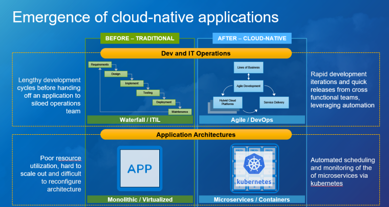
In the past, companies would rely on Waterfall development and ITIL change management operational practices. This meant organizations had to plan for:
- Long Development cycles before handing an application to ops
- IT ops often resisting change and slow innovation
Now companies want to take advantage of a new development cycle called Agile along with DevOps operational practices. This new foundation for IT accelerates innovation through:
- Rapid iteration and quick releases
- Collaboration via involving the IT ops teams throughout the process
Operational practices aren’t the only evolving element in today’s enterprises; application architectures are quickly changing as well. For years, monolithic architectures were the standard for application architectures. These types of applications had great power and efficiency and run on virtual machines. However, these applications have proven costly to reconfigure, update, and take a long time to load. In cloud-native applications, components of the app are segmented into microservices, which are then bundled and deployed via containers. This container/microservice relationship allows cloud-native apps to be updated and scaled independently. To manage these containerized workloads, organizations use an open-source management platform called Kubernetes. To give a real-world example, imagine monolithic apps like a freight train – there is a lot of power and capacity but it takes a long time to load and is not easy to reconfigure. Whereas cloud-native apps function more like a fleet of delivery vehicles with reduced capacity but resilient and flexible in changing the payload or adapting capacity as needed. A fleet of delivery vehicles needs a conductor to schedule and coordinate the service, and that is the role that Kubernetes plays for containers in a cloud-native environment. Both approaches are present in today’s modern apps but the speed and flexibility of cloud-native apps shifting priorities everywhere.
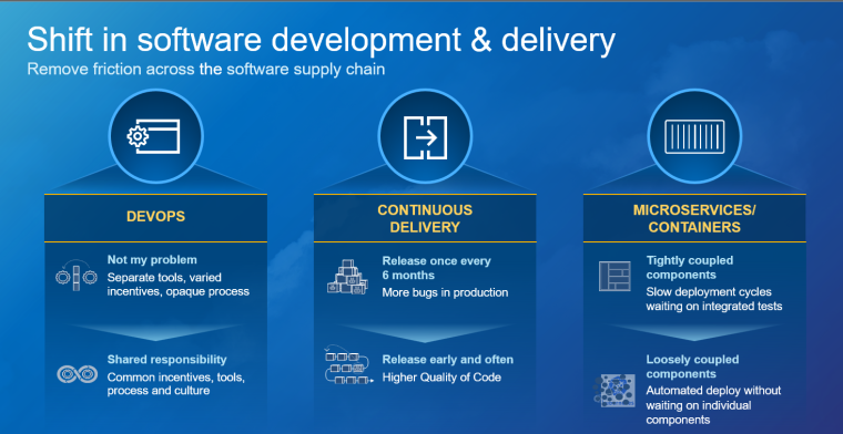
Let’s dig more into this shift in software development and delivery. Leading this shift is the use of microservices, which are loosely coupled components that are self-contained, highly available, and easily deployable, and with containers that provide these microservices with lightweight packages capable of resource utilization efficiencies, enable those microservices patterns. They provide a ‘build once, run anywhere flexibility with the scale that developers are embracing. Then came Kubernetes. Kubernetes is an open-source system for automating deployment, scaling, and management of containerized applications. It has become the industry “go-to” for more service discovery, load balancing, storage orchestration. With agile development comes the need for speed and continuous delivery which, with the right tools and infrastructure can create the right business outcomes as demands increase. With the advent of flexible cloud-native applications; DevOps teams formed and created their own agile frameworks that in addition to increasing delivery of code with less dysfunction and overhead of traditional models whereby intentionally or unintentionally bypassing IT Operations’ best practices and the opportunity to build modern IT infrastructures to support their development initiatives, as well as enhance them.
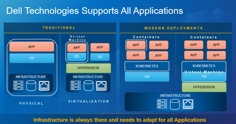
As traditional models for software development evolve, so does the infrastructure that supports it. IT Operations’ best practices can be applied to these new models through the Enterprise level data management tools that Dell Technologies’ provides. DevOps teams require seamless, non-disruptive, and reliable mechanisms to continue to meet business demands with agility and scale. With Dell Technologies” broad portfolio designed for modern and flexible IT growth, customers can employ end-to-end storage, data protection, compute and open networking solutions that support accelerated container adoption. Developers can create and integrate modern applications by relying on accessible open-source integrated frameworks and tools across bare metal, virtual, and containerized platforms. Dell enables support for DevOps elasticity and real-time benefits for container and Kubernetes platforms’ applying best practices based on their own design and needs.
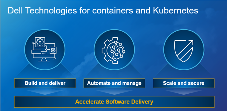
Dell Technologies aligns developers and IT operations, empowering them to design and operate cloud-native organizations while achieving business demands and increasing quality outputs. With the support of industry standards built on containers such as Containers’ storage interfaces, Plug-ins with container storage modules, PowerProtect data manager can Availability is the most important aspect of data that customers and different levels of business ultimately care about from about every angle; especially securely accessed data whether it be on-premises, in the cloud. Though developers seem to claim they understand Kubernetes inside and out, they miss out on features at the IT operations level that we can provide. With a big portfolio such as ours, we must understand what maturity level the customer is in. For the storage administrator, they will defer using their PowerMax or VxRail; if they want to continue to purchase these products, they would appreciate built-in containers/Kubernetes support that is easy to onboard without disrupting their developers. At the application layer, you may be employing Kubernetes or OpenShift well into the software-defined journey and PowerFlex would be an optional choice. GitHub CSI downloads exceed 1 million downloads. Kubernetes developers know nothing about storage except local storage servers and drives; whereby their operational partners care about resiliency, snapshot, restore, replication, compression, and security. With the variety of storage solutions, having CSI plug-ins and Container Storage Modules simplifies deployment choices, emphasis on applying operational best practices.
Build:
- Cloud-Native Computing Foundation (CNCF) SIG contributor
- Complete E2E integrated industry-standard APIs
- Self-service CSI driver workflows
- GitHub repository for developers
- Partner integrations with VMware Tanzu, Red Hat OpenShift, Google Anthos, Rancher, others
- DevOps and IaC integration with Ansible, Terraform, Puppet, ServiceNow, vRO, Python, Powershell, etc.
- Kubernetes Certified Service Provider (KCSP) Consultant Services
Automate & Manage:
- Container storage modules (CSM)
- Data replication across data centers
- RBAC authorization
- Observability
- Resiliency (disaster recovery & avoidance)
- Single platform, Kubernetes & application-aware data protection
- Application consistent backups
- MySQL, MongoDB, Cassandra, Postgres, etc.
- Infrastructure Automation & Lifecycle Management
- API driven software-defined infrastructure with automated lifecycle management
- Policy-based protection
- Replication, retention, tiering to S3-compatible object storage, SLA reporting
- Provide in-cloud options for developers with support for AWS, Azure backup policies
Scale & Secure:
- Provisioning and automating policies
- Extract data value in real-time through open networking and server/compute
- Deploy data protection backup and restores via PowerProtect Data Manager
- Integrated Systems; VxBlock, VxRail, PowerFlex, Azure Stack
- Manage Kubernetes with PowerScale in multi-cloud environments
- Accelerate with edge / bare metal via Kubespray / Streaming Data Platform (SDP) w/ Ready Stack for Red Hat OpenShift platforms
- Obtain seamless security and secure critical data via CloudLink
Ok, let’s talk Kubernetes.
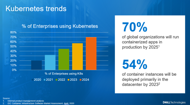
Kubernetes is really starting to pick up, as you can see in the above graphs, by 2025, it is expected that up to 70% of the enterprises out there, will be using Kubernetes AND that, 54% will be deployed primarily in their production environments! Yep, that means, we are way beyond the ‘Kicking the tires’ phase. A few weeks ago, I talked with my manager about these trends which you can see below.
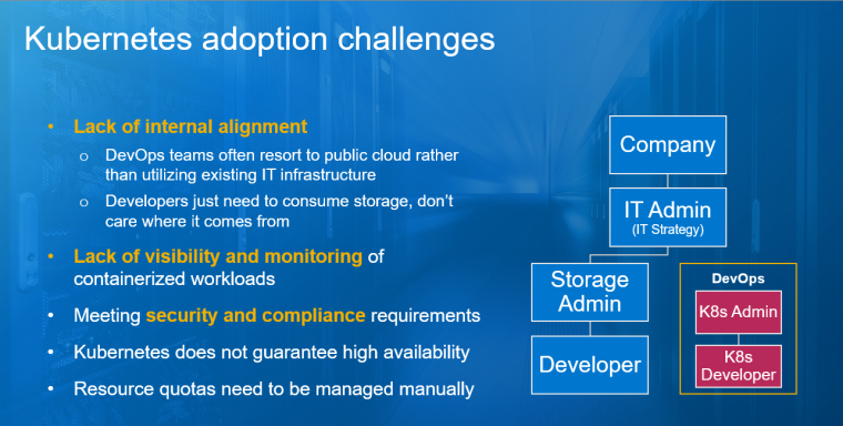
BUT, it’s not all rosy, Kubernetes provides a lot of challenges, to name a few:
Lack of internal alignment…shadow IT results… which leads to a harder job for the IT admins with lack of visibility and monitoring, and meeting security and compliance requirements. Kubernetes also cannot automatically guarantee that resources are properly allocated between different workloads running in a cluster. To set that up, you need to set up resource quotas manually. The opportunity is to align developers and IT operations by empowering them to design and operate cloud-native organizations while achieving business demands and increasing quality outputs.
In the next post, I will share the ‘What’ are we releasing to tackle these challenges...

Azure Arc Data Services on Dell EMC PowerStore
Thu, 04 Nov 2021 19:37:31 -0000
|Read Time: 0 minutes
Azure Data Services is a powerful data platform for building cloud and hybrid data applications. Both Microsoft and Dell Technologies see tremendous benefit in a hybrid computing approach. Therefore, when Microsoft announced Azure Arc and Azure Arc-enabled data services as a way to enable hybrid cloud, this was exciting news!
Enhancing value
Dell Technologies is always looking for ways to bring value to customers by not only developing our own world-class solutions, but also working with key technology partners. The goal is to provide the best experience for critical business applications. As a key Microsoft partner, Dell Technologies looks for opportunities to perform co-engineering and validation whenever possible. We participated in the Azure Arc-enabled Data Services validation process, provided feedback into the program, and worked to validate several Dell EMC products for use with Azure Arc Data Services.
Big announcement
When Microsoft announced general availability of Azure Arc-enabled data services earlier this year, Dell Technologies was there with several supported platforms and solutions from Day 1. The biggest announcement was around Azure Arc-enabled data services with APEX Data Storage Services. However, what you may have missed is that Dell EMC PowerStore is also validated on Azure Arc-enabled data services!
What does this validation mean?
Basically, what this validation means is that Dell Technologies has run a series of tests on the certified solutions to ensure that our solutions provide the required features and integrations. The results of the testing were then reviewed and approved by Microsoft. In the case of PowerStore, both PowerStore X and PowerStore T versions were fully validated. Full details of the validation program are available on GitHub.
Go forth and deploy with confidence knowing that the Dell EMC PowerStore platform is fully validated for Azure Arc!
More information
In addition to PowerStore, Dell Technologies leads the way in certified platforms. Additional details about this validation can be found here.
For more information, you can find lots of great material and detailed examples for Dell EMC PowerStore here: Databases and Data Analytics | Dell Technologies Info Hub
You can find complete information on all Dell EMC storage products on Dell Technologies Info Hub.

What’s new with Dell EMC AppSync Copy Management Software and PowerStore
Thu, 21 Jul 2022 16:25:34 -0000
|Read Time: 0 minutes
For those who don’t already know, Dell EMC AppSync is a software package that can simplify and automate the process of generating and consuming copies of production data. At a high-level, AppSync can perform end to end operations such as quiescing the database, snapping the volumes, and mounting and recovering the database. For many end users, these operations can be difficult without AppSync, because of different applications and storage platforms.
AppSync provides a single pane of glass and its workflows work the same, regardless of the underlying array or application. AppSync natively supports Oracle, Microsoft SQL Server, Microsoft Exchange, SAP HANA, VMware, and filesystems from various operating systems. The product also provides an extensible framework through plug-in scripts to deliver a copy data management solution for custom applications.
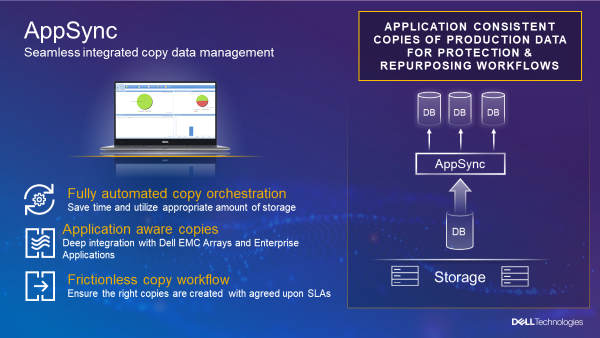
Customers use AppSync for repurposing data, operational recovery, and backup acceleration.
There are two primary workflows for AppSync:
- Protection workflows allow customers to schedule copy creation and expiration to meet service level objectives of operational recovery or backup acceleration.
- Repurposing workflows allow customers to schedule the creation and refresh of multi-generation copies.
Both workflows offer automated mount and recovery of the copy data.
AppSync is available as a 90-day full featured trial download, and provides two licensing options:
- The AppSync Basic license ships with all PowerStore systems.
- The AppSync Advanced license is fully featured and available for purchase with all Dell EMC primary arrays.
For supported configurations, see the AppSync support matrix. (You’ll need to create a Dell EMC account profile if you do not already have one.)
The latest version, AppSync 4.3 – released on July 13th, 2021 – contains many new features and enhancements, but in this blog I want to focus on the PowerStore system support and functionality. AppSync has supported PowerStore since version 4.1. Because PowerStore supports both licensing models mentioned above, testing it and implementing it into production is simple.
AppSync supports the discovery of both the PowerStore T and PowerStore X model hardware and multi-appliance clusters. The new PowerStore 500 is also supported: a low cost, entry level PowerStore system that can support up to 25 NVMe drives. Clustering the 500 model with other PowerStore 1000-9000 models is fully supported. For more details, check out the PowerStore 500 product page and the PowerStore Info Hub.
PowerStore 500
PowerStore can use both local and remote AppSync workflows: Protection and Repurposing. Production restore is supported for both local and remote. AppSync uses the PowerStore Snapshot and Thin Clone technologies embedded in the appliance, so copies are created instantly and efficiently. It also leverages PowerStore async native replication for remote copy management. (When replicating between two PowerStore systems, source to target, you can only have one target system.) The figure below shows how a PowerStore array is discovered in AppSync.
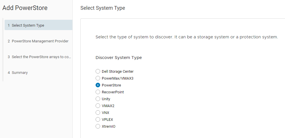
We have more sources of information about integrating AppSync and PowerStore. Here are some to get you started:
- Dell EMC PowerStore and AppSync Integration – This video shows how AppSync can automatically create remote application consistent copies on PowerStore for Microsoft SQL Server. (The configuration includes a PowerStore X model appliance at the source site, running AppSync and SQL Server virtual machines using PowerStore AppsON functionality. The remote site uses a PowerStore T model as the replication destination site.)
- Dell EMC PowerStore: AppSync – This white paper provides guidelines for integrating the two for copy management.
You can also find other AppSync related documents on the Dell Info Hub AppSync section.
We hope you have a great experience using these products together!
Author: Andrew Sirpis LinkedIn

What is PowerStoreCLI Filtering?
Thu, 14 Oct 2021 21:30:03 -0000
|Read Time: 0 minutes
What is PowerStoreCLI Filtering? With the sheer volume of features that are being pumped out with every Dell EMC PowerStore release, this may be a common question among other minor features that sometimes gets overlooked. That’s why I’m here to boast some helpful PowerStoreCLI tips and show why you just might want to use the filtering feature that got an update in PowerStoreOS 2.0.
PowerStoreCLI, also known as pstcli, is a light-weight command line interface application that installs on your client that allows you to manage, provision, and modify your PowerStore cluster.
For starters, check out the Dell EMC PowerStore CLI Reference Guide and Dell EMC PowerStore REST API Reference Guide on https://www.dell.com/powerstoredocs to see the wide variety of CLI and REST API commands available. You can also download the pstcli client from the Dell Product Support page.
Now when it comes to fetching information about the system through pstcli, we generally use the “show” action command to display needed information. This could be a list of volumes, replications, hosts, alerts, or what have you. Bottom line is you’re going to use the show command quite a bit and sometimes the output can be a little cumbersome to sift through if you don’t know what you’re looking for.
This is where filtering comes into play using the “-query” switch. When we use the query capabilities, you can fine-tune your output to focus rather precisely on what you’re looking for. Query supports various conditions (and, or, not) and operators such as ==, <, >, !=, like, and contains, to name a few. If you’re familiar with SQL, the condition and operator syntax is very similar to how you would type out SQL statements. But as with all pstcli commands, you can always put a “-help” at the end of a command if you can’t remember the syntax
Filtering your pstcli commands combined with custom scripts can be quite a powerful automation tool, allowing you to filter output directly from the source, rather than putting all your filtering logic on the client side. There are tons of ways to automate through scripting which I will save for another discussion. I’ll mainly be focusing on the command line filtering aspects from the PowerStore side. Let’s look at an example of how you can filter the output of your alerts with pstcli.
I’ll be using the commands in a session to reduce screenshot clutter, so you don’t see all the login information. You don’t need to use a session to use pstcli filtering, but it’s a neat way to get familiar with pstcli, without having to see all the login and password info on every command. If you don’t know how to establish a pstcli session to your PowerStore, I recommend checking out the Dell EMC PowerStore: CLI User Guide.
The basic alert command is “alert show”. This will blast out every cached alert on the system, both active and cleared alerts.
alert show
I only listed the first few alerts in this figure because this was a long-standing system with hundreds of cleared alerts and only a few active. As you can see, there is a lot of information in the output. By default, most of the columns are abbreviated unless you have a very wide terminal and because of this, the output may not give much insight on what’s happening with the system at first glance. Combine that with the fact that you may have 100s of lines to look at. This is where filtering can really clear things up and provide you a more targeted view of your command output.
So, let’s apply some filtering. Perhaps I only want to see active alerts and ones that have a severity other than Info.
alert show -query ‘state == ACTIVE && severity != Info’
There, now my output went from 100+ lines to only displaying five alerts!
Take it one step further with the -select switch to filter out the extra columns. Let’s say my script only needs the event ID, Event Code, Timestamp, and Severity.
alert show -select id,event_code,raised_timestamp,severity -query ‘state == ACTIVE && severity != Info’
By the way, you if you prefer REST API, you can apply the same filtering logic to your REST commands! Here’s a sample REST command using curl that would return the same output from our example above:
$curl -k -u admin:<PowerStore_password> -X GET "https://<PowerStore_IP>/api/rest/alert?select=id,event_code,raised_timestamp,severity?severity=neq.Info&state=eq.ACTIVE" -H "accept: application/json"
There we go, we’ve filtered through tons of alerts to only seeing the five active alerts that we are interested in and at the same time only viewing the information we need. From here, as you can imagine the possibilities are endless!
For more information on PowerStore, I suggest checking out the PowerStore Info Hub.
Author: Ryan Meyer LinkedIn

Introduction to the PowerStore Platform Offerings and their Benefits

Thu, 21 Jul 2022 16:24:17 -0000
|Read Time: 0 minutes
In May 2020, we released Dell EMC PowerStore, our groundbreaking storage family with a new container-based microservices architecture that is driven by machine learning. This versatile platform includes advanced storage technologies and a performance-centric design that delivers scale-up and scale-out capabilities, always-on data reduction, and support for next-generation media.
PowerStore provides a data-centric, intelligent, and adaptable infrastructure that supports both traditional and modern workloads.
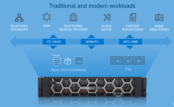
Figure 1. Overview of PowerStore
Let’s start by going over the hardware details for the appliance. The PowerStore appliance is a 2U, two-node, all NVMe Base Enclosure with an active/active architecture. Each node has access to the same storage, with Active-optimized/Active-unoptimized front-end connectivity.
Hardware
The following figures show the front and back views of the PowerStore appliance:
Figure 2. Front view of PowerStore appliance

Figure 3. Back view of PowerStore 1000-9000 appliance
The PowerStore models start at the PowerStore 500 all the way up to the PowerStore 9000. The configurations available vary by model. This table provides a comparison of the different models:
| PowerStore Model | 500 | 1000 | 3000 | 5000 | 7000 | 9000 | |
|---|---|---|---|---|---|---|---|
NVMe NVRAM drives | 0 | 2 | 4 | ||||
Capacity (cluster) | 28.57 TB to 11.36 PB Effective (11.52 TB to 3.59 PB Raw) | ||||||
Max drives (appliance / cluster) | 25 | 96 / 384 | |||||
Expansion (appliance) | None | Add up to three expansion enclosures per appliance | |||||
AppsON | N/A | X models | |||||
Drive types | NVMe SSD, NVMe SCM | NVMe SSD, NVMe SCM, SAS SSD (Only on the expansion enclosures) | |||||
Clustering | Up to four appliances: Mix and match appliances of any model/config of the same type | ||||||
Embedded ports | 4-port card: | 25/10/1 GbE | 25/10/1 GbE optical/SFP+ and Twinax or 10/1 GbE BaseT | ||||
2-port card: | 10/1 GbE optical/SFP+ and Twinax | None | |||||
IO Modules (2 per node) | 32/16/8 Gb FC or 16/8/4 FC | ||||||
Front-End Connectivity | FC: 32 Gb NVMe/FC, 32/16/8Gb FC | ||||||
For more details about the PowerStore hardware, see the Introduction to the Platform white paper.
Model types
PowerStore comes in two model types: PowerStore T and PowerStore X. Both types run the PowerStoreOS.
PowerStore T
For the PowerStore T, the PowerStoreOS runs on the purpose-built hardware as shown in Figure 4. PowerStore T can support a unified deployment with the option to run block, file, and vVol workloads, all from within the same appliance.
PowerStore T supports the following:
- SAN (NVMe/FC, FC and iSCSI)
- NAS (NFS, SMB, FTP and SFTP)
- vVol (FC and iSCSI)
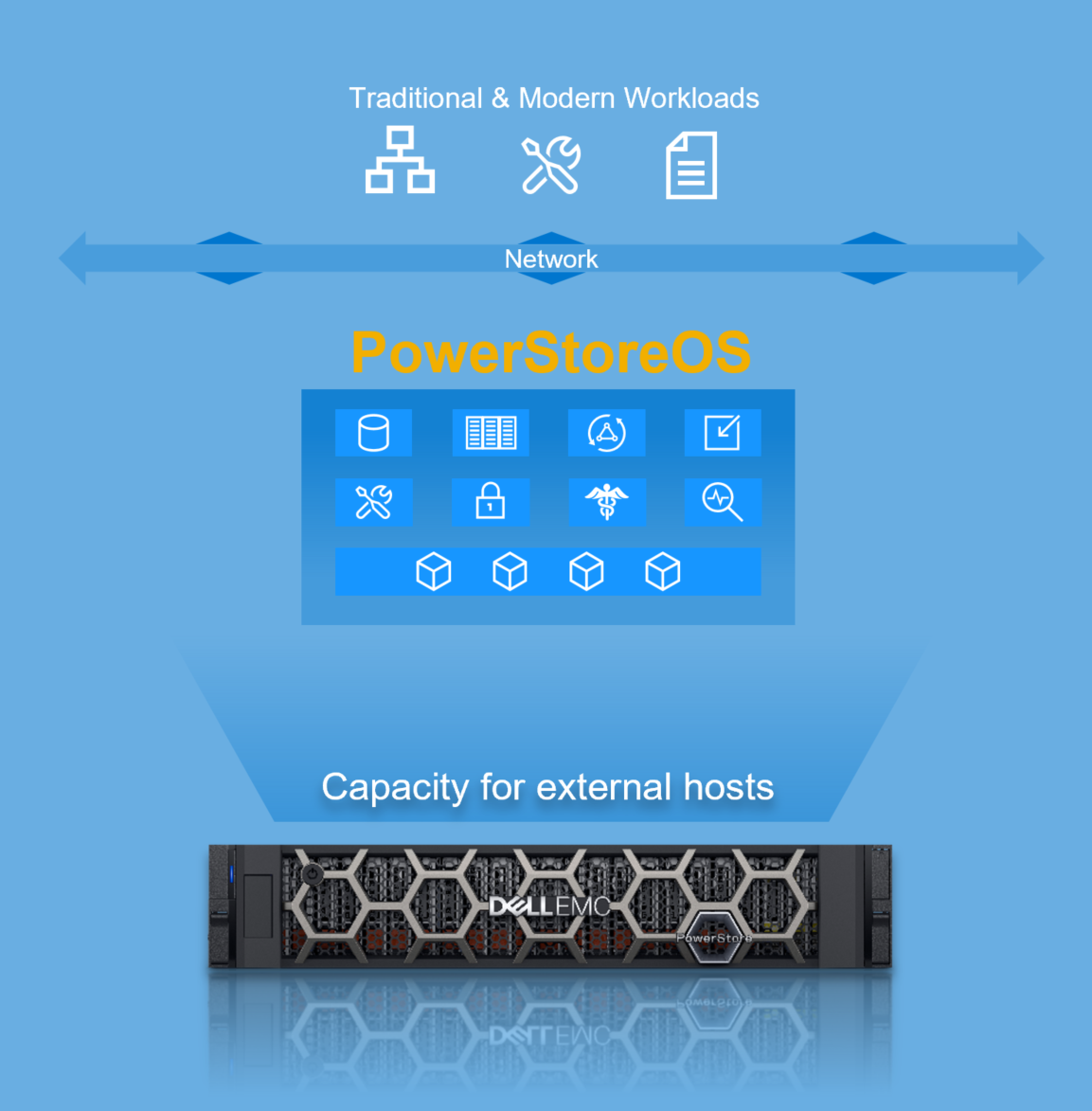
Figure 4. PowerStore T
PowerStore T has two deployment modes to ensure that the platform delivers maximum performance for each use case. The deployment mode is a one-time setting configured when using the Initial Configuration Wizard. The following describes the two deployment modes available as part of the storage configuration: unified and block optimized.
- Unified:
- Default storage configuration (factory state)
- Supports SAN, NAS, and vVol
- Resources shared between block and file components
- Block Optimized:
- Alternate storage configuration (requires a quick reboot)
- Supports SAN and vVol
- Resources dedicated to block components
Depending on the storage configuration you set, the PowerStore T can cover various use cases, and and fulfill many of the use cases that a traditional storage array would, but with added benefits.
Some use cases that the PowerStore T can cover:
- With the Unified storage configuration: file workloads are supported. This entails support for home directories, content repositories, SMB shares, NFS exports, multiprotocol file systems (access through SMB and NFS in parallel), and more. For more details, see the File Capabilities white paper.
- With the Block Optimized storage configuration: For customers running block only workloads, you can leverage PowerStore T with the traditional FC and iSCSI protocols, in addition to running NVMe/FC.
Now for our second model type, PowerStore X.
PowerStore X
PowerStore X also runs the same PowerStoreOS as the PowerStore T but it is virtualized as Virtual Machines (VMs) running on VMware ESXi hosts that run directly on the purpose-built hardware. This model type includes one of the key features known as AppsON. As the name suggests, it can run your typical block workload in conjunction with running customer and application VMs. Figure 5 provides a glimpse of this model.
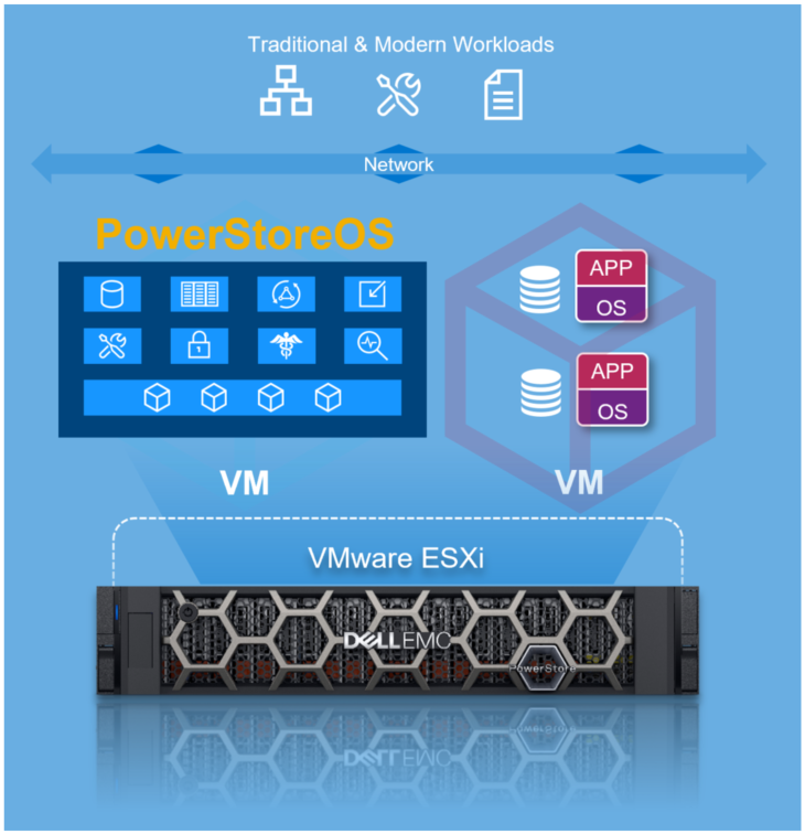
Figure 5. PowerStore X
PowerStore X supports the following:
- SAN (NVMe/FC, FC, and iSCSI)
- vVol (FC and iSCSI)
- Embedded Applications (Virtual Machines)
You can leverage AppsON for multiple use cases that span Edge, Remote Office, data intensive applications, and so on.
Some example use cases are:
- Applications: As organizations thrive to simplify, while continuing to keep up with ongoing accelerated demands, AppsON can be leveraged to help consolidate the infrastructure that is running business-critical applications. It can host a broad range of applications, such as MongoDB (MongoDB Solution Guide, Microsoft SQL Server (Microsoft SQL Server Best Practices), or Splunk (Capture the Power of Splunk with Dell EMC PowerStore) to name a few. For white papers regarding databases and data analytics, see the databases and data analytics page.
- VM Mobility: As mentioned previously, with AppsON we can host VMs natively within PowerStore. This allows for greater flexibility through VMware vSphere because we can leverage Compute vMotion and Storage vMotion to seamlessly move applications between PowerStore and other VMware targets. For example, you can deploy applications on external ESXi hosts, hyperconverged infrastructure (that is, Dell EMC VxRail), or directly on the PowerStore appliance that migrate transparently between them.
We have provided a high-level overview and some examples. There are additional use cases that PowerStore can cover.
Resources
Technical documentation
To learn more about the different features that PowerStore provides, see our technical white papers.
Demos and Hands-on Labs
To see how PowerStore’s features work and integrate with different applications, see the PowerStore Demos YouTube playlist.
To gain firsthand experience with PowerStore, see our Hands-On Labs site for multiple labs.
Author: Kenneth Avilés Padilla LinkedIn

Kubernetes Brings Self-service Storage
Tue, 28 Sep 2021 18:49:52 -0000
|Read Time: 0 minutes
There are all sorts of articles and information on various benefits of Kubernetes and container-based applications. When I first started using Kubernetes (K8s) a couple of years ago I noticed that storage, or Persistent Storage as it is known in K8s, has a new and exciting twist to storage management. Using the Container Storage Interface (CSI), storage provisioning is automated, providing real self-service for storage. Once my storage appliance was set up and my Dell EMC CSI driver was deployed, I was entirely managing my storage provisioning from within K8s!
Self-service realized
Earlier in my career as a SQL Server Database Administrator (DBA), I would have to be very planful about my storage requirements, submit a request to the storage team, listen to them moan and groan as if I asked for their first born child, then ultimately provide half of the storage I requested. As my data requirements grew, I would have to repeat this process each time I needed more storage. In their defense, this was several years ago before data reduction and thin provisioning were common.
When running stateful applications and database engines, such as Microsoft SQL Server on K8s, the application owner or database administrator no longer needs to involve the storage administrator when provisioning storage. Volume creation, volume deletion, host mapping, and even volume expansion and snapshots are handled through the CSI driver! All the common functions that you need for day-to-day storage management data are provided by the K8s control plane through common commands.
K8s storage management
When Persistent Storage is required in Kubernetes, using the K8s control plane commands, you create a Persistent Volume Claim (PVC). The PVC contains basic information such as the name, storage type, and the size.
To increase the volume size, you simply modify the size in the PVC definition. Want to manage snapshots? That too can also be done through K8s commands. When it’s time to delete the volume, simply delete the PVC.
Because the CSI storage interface is generic, you don’t need to know the details of the storage appliance. Those details are contained in the CSI driver configuration and a storage class that references it. Therefore, the provisioning commands are the same across different storage appliances.
Rethinking storage provisioning
It’s a whole new approach to managing storage for data hungry applications that not only enables application owners but also challenges how storage management is done and the traditional roles in a classic IT organization. With great power comes great responsibility!
For more information, you can find lots of great material and detailed examples for Dell EMC PowerStore here: Databases and Data Analytics | Dell Technologies Info Hub
You can find complete information on all Dell EMC storage products on Dell Technologies Info Hub.
All Dell EMC CSI drivers and complete documentation can be found on GitHub. Complete information on Kubernetes and CSI is also found on GitHub.
Author: Doug Bernhardt
Twitter: @DougBern
www.linkedin.com/in/doug-bernhardt-data