


Full Redundancy vs. Fault Tolerant Redundancy for PowerEdge Server PSUs
Download PDFMon, 16 Jan 2023 13:44:19 -0000
|Read Time: 0 minutes
Summary
Understanding the power supply redundancy options to facilitate your server is important for users seeking to prioritize certain use cases over others, such as full, consistent performance during fault conditions or higher performance and capabilities during normal operating conditions. This DfD will discuss two PSU redundancy options; Full Redundancy (FR) and Fault Tolerant Redundancy (FTR), and explain when it may be advantageous for a user to adopt one of these solutions over the other.
Introduction
Customers need power redundancy to maintain application uptime. However, few know that there is more than one type of redundancy to consider, and the best option depends on several factors. This DfD will explain two power supply unit (PSU) redundancy options – Full Redundancy (FR) and Fault Tolerance Redundancy (FTR). Dell Technologies now enables customers to select between these at point of sale for select platforms. Understanding these PSU redundancy options is critical as the selection will determine the minimum PSU capacity required to support the targeted PowerEdge server configuration.
FR configurations run at full performance during normal operating conditions and after PSU redundancy loss (if a PSU goes down due to input loss or fault). FR is optimized for consistent performance, thus the minimum PSU capacity allowed will ensure that the platform configurations full performance power requirements can be supported. In summary – PowerEdge users looking to adopt FR gain consistent PSU performance during normal and fault operating conditions, but will require a PSU capacity capable of supporting full performance power requirements.
FTR configurations run at full performance during normal operating conditions, but after PSU redundancy loss, intelligent platform power control loops may dynamically reduce system performance to limit the platform’s power consumption within the capacity of the healthy PSU. FTR is optimized to enable support for richer platform configurations within a target PSU capacity that provides additional performance and capabilities during normal operations. The target PSU capacity is driven by multiple potential factors, such as:
- A larger PSU capacity is not available
- PSU capacity is right sized for a typical workload for CapEx and/or OpEx savings
- Require configuration support within the capacity of PSUs with C14 inlet connector
- Require configuration support within the low-line AC (110V) power limits of C14 and C20 inlet connectors
- Require PSU efficiency level and/or input type that is only available in limited PSU capacities
To support richer configurations with more perfomance and capability during normal operation, FTR takes advantage of the additional PSU capacity from the redundant PSU during normal operation. However, when the redundant PSU fails, FTR must take away performance to compensate for loss of additional power capacity that enabled the additional perfomance and capability. In summary – PowerEdge users looking to adopt FTR will have richer platform configuration options within a PSU capacity limit , but must assess the potential impact of performance degradation to their workload.
Addressing the Negative Stereotype
Historically, FR has been deemed as the superior PSU redundancy option. Customers viewed FTR concepts as a “trick” to compensate for a design limitation. Dell Technologies was originally opposed to supporting FTR due to the negative stigma associated with it.
Eventually, Dell Technologies added support for FTR to PowerEdge platforms because platform power requirements were increasing faster than PSU technology advancements. FTR was not advertised or marketed despite being an essential technology to support platform configurations that customers wanted. Only limited references were made in technical white papers.
As FTR concepts have become standard within the industry, it is now seen as a minor trade-off for a greater upside – a solution to various modern-day datacenter power challenges that will not require additional PSUs, greater PSU capacity, or a loss in redundancy. As component density and quantity continues to increase with each generation, customers now require more and more power yet still have the same mechanical (limited space) or electrical (power budget) constraints. FTR resolves these challenges by allowing the total load to exceed the capacity of a single PSU during normal operation by utilizing the additional capacity of the redundant PSU, which results in a considerable increase in power standards and peaks during normal operating conditions.
That is what is so ironic about FTR – its “fatal flaw” of throttling has also become its “saving grace”. FR does not allow for performance variations while FTR does, and this creates use cases where users can leverage FTR to support richer configurations without upgrading their PSU infrastructure. Figure 1 illustrates power, performance, and capability during normal operating conditions, while Figure 2 illustrates how power, performance, and capability during a PSU redundancy loss event:
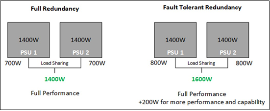
Figure 1 – Example of FR/FTR performance during normal operating conditions
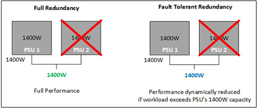
Figure 2 – Example of FR/FTR performance after PSU redundancy loss occurs
User Navigation Example
The latest-generation of PowerEdge servers (15G) support the option to choose Full Redundancy or Fault Tolerant Redundancy via PSU options at point of sale. Users can configure their servers via the sales portal on www.dell.com and have the option to click a step deeper via the Dell Enterprise Infrastructure Planning Tool (EIPT) for more granular guidance, as shown in Figure 3. Reviewing the PSU options in the PSU Guide and workload power details in EIPT will help PowerEdge users fine-tune their PSU configuration.
- Gray – PSU capacity options cannot support the platform configuration
- White – FTR. PSU capacity options can support the platform configuration, but peformance may be degraded after PSU redundancy loss
- Green – FR. Minimum PSU capacity that can support the configuration with full performance during normal and fault operating conditions. Capacities greater than this capacity are also FR
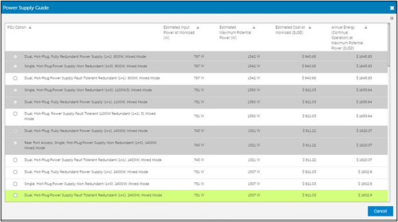
Figure 3 – Dell EIPT tool displaying various power and cost metrics based on configured PowerEdge server
For example, as seen in Figure 3, 2400W is required for FR. FTR enables the configuration to be supported with 1400W, 1100W, or 800W PSUs. If the platform were the R650 instead of the R750, the 2400W would not be an available option because it is the larger 86mm form factor which is not supported in the 1U 650. FTR enables this configuration to be supported when it could not be otherwise.
If the customer required the PSU input voltage to be low line AC (110V), the 1400W and 1100W PSUs would be limited to a 1050W output. The 2400W PSU would be limited to 1400W. Since 2400W is required for FR, this configuration could not be supported with FR. FTR enables this configuration to be supported with low line AC input.
EIPT estimates the typical power consumption with the 2400W PSU for the target workload to be 751W. The Maximum Potential Power (power virus) is estimated to be 1307W. Note, these are input power estimates, thus they are a little higher than the output power estimate and vary based on capacity due the PSU efficiency curves. The 2400W is the FR recommendation over the 1400W despite the worst case 1307W sustained power estimate because there are short duration power transie nts that exceed the 1400W power delivery capability.
FTR enables the customer to optimize CapEx and OpEx by right sizing their PSU capacity. 1400W could be an option to right size and still provide significant capacity to eliminate or minimize any potential performance degradation. With an estimated 751W typical power, the 1100W and 800W would be more aggress PSU right size options that provides the needed power for the user’s workload assuming the workload does not change. If the workload or environment changes AND PSU redundancy is lost, FTR will manage the load increase to avoid unexpected shutdown and potential data loss.
Pros, Cons and Use Cases
Full Redundancy
- Pros
- Consistent performance during normal operating conditions and PSU redundancy loss
- No PSU throttling
- Cons
- Maximum sustained power is constrained to the specifications of one PSU
- Does not utilize the additional capacity of the redundant PSU during normal operation
- Use Cases
- Configurations that meet power requirements with only one PSU
- Workloads that are sensitive to performance variations, such as HPC
- Platforms that do not have mechanical constraints, such as limited space for more PSUs
- Data centers that do not have electrical constraints, such as low-line AC
Fault Tolerant Redundancy
- Pros
- Allows for increased sustained perfomance during normal operating conditions
- Utilizes the additional capacity of the redundant PSU during normal operation
- Eliminates cost of purchasing additional or higher capacity PSU
- Does not require giving up PSU redundancy
- Does not require down-grading platform configuration to fit within target PSU capacity
- Cons
- Performance may be reduced during PSU redundancy loss
- Use Cases
- Configurations that would meet power requirements with the performance increase coming from the redundant PSU
- Platforms that have mechanical constraints, such as limited space for more PSUs
- Data centers that have electrical constraints, such as low-line AC
Conclusion
Dell Technologies supports both Full Redundancy (FR) and Fault Tolerant Redundancy (FTR) options for the latest-generation (15G) of PowerEdge servers. By understanding the pros and cons of each redundancy type, users can optimize their server by upgrading or downgrading their configuration infrastructure based on what type of power redundancy they desire.
Related Documents

Dell PowerEdge Servers: New PSU Layout Delivers Improved Airflow and PCIe Feature Set

Mon, 16 Jan 2023 13:44:29 -0000
|Read Time: 0 minutes
Summary
The next generation of PowerEdge servers brings a new Power Supply layout that allows for improved system cooling and helps enable support for Gen4 PCIe cards. Purchase with confidence, knowing that these system improvements help ensure that the next generation PowerEdge server continues to deliver best-in- class features.
Split Power Supplies
The layout of previous generations of Dell PowerEdge rack servers utilized two power supplies grouped on one side of the chassis. Dell’s next generation of PowerEdge servers improves the mechanical design with the two power supplies split – one on each side of the chassis. This new system and power supply layout offers several tangible benefits over the older system design.
Balanced Airflow
In prior generations, the location of the inner power supply was near the CPU exhaust airflow. Due to the proximity to the CPU, the PSU was continually exposed to air that is heated to high temperatures from moving through the CPU heatsink. With each new CPU refresh, power continues to increase and PSU cooling becomes exponentially more challenging. Additionally, the PSU location compounded the thermal challenges because it was also an obstruction to airflow moving freely through the CPU heatsink.
The split power supply placement in the next generation of PowerEdge servers allows for both low temperature airflow for PSU cooling and less obstruction for cooling high power CPUs. The result is that system airflow is balanced across the width of the system providing more uniform airflow for CPU, Memory, and PCIe cards in the rear of the chassis.
Support for Gen4 PCIe
One of the goals of the new architectures in the next generation of PowerEdge servers is to support faster I/O speeds, such as PCIe Gen 4, and beyond. PCIe Gen 4 doubles the lane speed to 16GT/s from the previous generation. A key element in PCIe performance is the length of PCIe traces. With the new system layout, a main goal was to shorten the overall PCIe trace lengths in the topology, including traces in the motherboard. By positioning PSU’s at both edges, the I/O traces to connectors can be shortened for both processors. This is the optimal physical layout for PCIe Gen 4 and will enable even faster speeds for future platforms. The shorter PCIe traces translate into better system costs and improved Signal Integrity for more reliable performance across a broad variety of customer applications.
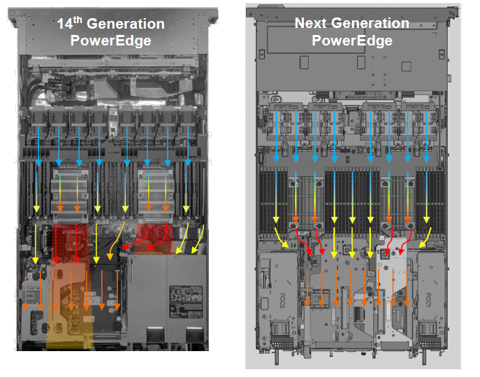
Balanced Airflow Illustration
The illustration below shows the 14G Generation Server layout (left image) with PSUs located on one side of the chassis. In this layout it is evident that system airflow and PSU cooling are not optimized. In the 15th Generation layout on the right, the dual power are split, one on each side of the chassis. The split PSU layout helps to balance the system airflow, reduce PSU operating temperatures, and allows for PCIe Gen4 card support and thus an overall more optimal system design layout.
In Conclusion
PowerEdge servers continue to deliver best-in-class features. The new PowerEdge servers have the PSUs on both rear sides of the server, improving chassis airflow, overall thermal efficiency and allows for Gen4 PCIe card support.

Dell Technologies Direct Liquid Cooling Support for New PowerEdge Servers
Mon, 16 Jan 2023 13:44:21 -0000
|Read Time: 0 minutes
Summary
Liquid cooling is a very effective method of capturing heat commonly produced by semi- conductors, such as processors and memory, and transferring it to an isolated region to dissipate. For the release of the new Intel and AMD-based PowerEdge servers, Dell Technologies is offering a direct liquid cooling solution to ensure that customer cooling needs are met. This DfD will educate readers on how the Dell Technologies direct liquid cooling solution works, which PowerEdge servers support them, and why this solution is advantageous for data centers.
Introduction
New 15G PowerEdge platforms will offer CPUs with higher power than ever before. Dell is introducing new Direct Liquid Cooling (DLC) solutions to effectively manage these growing thermal challenges. Dell DLC solutions cool the CPU with warm liquid which has much greater (~4x) heat capacity versus air. Thus, DLC is a higher performance cooling solution for managing the CPU temperature while also enabling higher performance and better reliability. Because DLC solutions are more efficient at extracting heat, this reduces the burden on server system fans as well as the data center’s cooling infrastructure, improving sustainability and saving customers money.
New PowerEdge Server Support
Dell is expanding our portfolio of platforms with factory-installed DLC solution, from dense compute C-series to our 1U and 2U rack-mount servers. The PowerEdge servers below offer DLC cooling on the newest Intel and AMD processors:
- C6520
- C6525
- R6525
- R7525
- R650
- R750
- R750XA
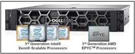
Figure 1 - Multiple PowerEdge servers with new Intel and AMD processors will support the Dell Technologies DLC
Direct Liquid Cooling Technology
DLC uses the exceptional thermal capacity of liquid to absorb and remove heat created by new high-power processors. Cold plates are attached directly to the processors (see Figure 2), and then coolant captures and removes the heat from the system to a heat exchanger located in the rack or row. This heat load is removed from the datacenter via a warm water loop, potentially bypassing the expensive chiller system. By replacing (or supplementing) conventional air-cooling with higher-efficient liquid cooling, the overall operational efficiency of the data center is improved.
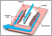
Figure 2 - DLC example of a cold plate and coolant loop
New Features and Solutions
Leaking Sensing Technology
Leak Sense technology is a new feature now included with all Dell DLC solutions, providing customers with the knowledge that potential issues will be found and reported quickly. If a coolant leak occurs, the system’s leak sensor will log an alert in the iDRAC system. Three errors can be reported: small leak (warning), large leak (critical), leak sensor error (warning – indicates the issue with the leak detection board). These error detections can be configured to take meaningful actions, such as raise an alert or power-off a server.
POD Solution
Whereas a node-level DLC solution captures between 50%-60% of a server’s internal heat (depending on the configuration), the Dell Technologies rack-level POD solution concept is designed for total heat capture. The POD solution contains front and back containment for racks of DLC servers, plus an InRow Cooler integrated between the IT racks to capture any remaining heat. Figure 3 illustrates a POD solution example.
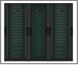
Figure 3 - Pod solution containing two outer racks with node-level DLC and one middle InRow Cooler
Benefits of Liquid Cooling Implementation
- Increased System Cooling Capacity – DLC enables system configurations that may not possible with air cooling alone, such as high TDP CPUs, dense storage and/or add-in cards.
- Improved Energy Efficiency (PUE) – The DLC cold plate solution reduces energy costs by up to 45% relative to cooled air 1, and helps extend the life of existing air infrastructure
- Higher Compute Density – For the Ice Lake based C6520 system, DLC cooling supports of up to 25% more cores per rack. For the Milan based C6525 system (with backplane configuration supporting storage drives), DLC cooling enables 2x the core count over air-cooling alone.
- 3.1x ROI Within 4 Years – The cost of pairing DLC with existing PowerEdge cooling tower infrastructure typically breaks even within 1.3 years and yields a 3.1x payback within 4 years 2
- Swift Serviceability – The CPU DLC cold plate solution attaches with four screws, making service quick and simple.
Conclusion
The Dell Technologies DLC solution enables PowerEdge server components to take on dense workloads while staying within their required thermal limits. Customers can maximize the utilization of their datacenters with confidence knowing they have the best efficiency, ROI and flexibility that a thermal design has to offer.
- Based on Dell EMC internal analysis, March 2021, comparing hypothetical air-cooled data center with a cooling PUE of 0.62 to a hybrid data center with a cooling PUE of 0.34. A PUE of 0.21 was assigned to all overhead not attributed to cooling. Operating costs and other factors will cause results to vary. RS Means industry standards cost basis was used to measure typical cooling infrastructure costs and determine projected savings.
- Based on Dell EMC internal analysis, March 2021 comparing a hypothetical air-cooled data center to a hybrid data center. Assuming 1244 nodes, the air cooled data center uses 1825 kW whereas the hybrid uses 1544 kW. Individual operating costs and other factors will vary the results. RS Means industry standards cost basis was used to measure typical cooling infrastructure costs and determine projected savings. Based on Dell EMC internal analysis, calculating the capital cost of DLC minus the amount of CRAH, pumps, chiller, and tower to equal the net cost of DLC, and examining the operational costs of a hypothetical air-cooled data center and a hybrid data center to determine ROI. Assumes a high wattage CPU. Schneider Electric developed an analytical model that ascribes operating costs to the various types of facility infrastructure equipment. Electricity costs and other factors will vary the results. RS Means industry standards cost basis was used to estimate cooling infrastructure costs and determine projected savings.