


Dell Technologies Focuses on Standardizing EDSFF Form Factor for Future Servers
Download PDFMon, 16 Jan 2023 13:44:23 -0000
|Read Time: 0 minutes
Summary
As new technologies have developed over time, server adoption has broadened into a wide spectrum of new environments that dictate more efficient flash drive packaging. While the 2.5” SSD form factor retains its value for many applications, these emerging domains have driven the development of a new standard – EDSFF. This DfD will explain why the EDSFF family of form factors was designed, what the specific design of each drive form factor targets, and how EDSFF resolve challenges faced within the server industry.
Addressing Modern Industry Requirements
Server adoption has greatly expanded over the last decade and many of these new environments are very challenging from a density standpoint and space (size) perspective. Data centers and smaller distributed edge deployments call for specific enhancements to the current ubiquitous storage device form factor for SSDs, such as the 2.5”, U.2 NVMe SSD. This isn’t to say that the existing U.2 form factor is outlived, as it has earned its reputation as the industry standard for a reason, but rather that server technology is advancing at a rapid pace and we must ensure that new flash storage form factors are being developed to address future enterprise architectural requirements.
The Enterprise Datacenter Small Form Factor (EDSFF), or E3 family of form factors, was designed to accommodate future enterprise needs and requirements to address the below challenges:
- Signal Integrity (SI) - A new form factor must be able to support next generation high frequency interfaces. The connector system must support PCIe Gen 5 and PCIe Gen 6, and ideally would support interfaces beyond PCIe Gen 6.
- Multiple Device Types - A new form factor would ideally support multiple device types. These device types include NAND based SSDs, CXL storage class memory (SCM), computational storage devices, low end accelerators, and front facing I/O devices.
- Link Width - A new form factor must be able to support multiple host connection link widths. Different device types will require different link widths including PCIe x2, PCIe x4, PCIe x8, and PCIe x16 connections.
- Size - The size of a new form factor should work well in both 1U and 2U platforms. The size must be large enough to work with multiple device types, but not so large that it breaks traditional server architectures. The size should also be large enough to accommodate high performance NAND controllers, but not so large that it limits the total number of supported devices.
- Power - A new form factor must support a reasonable range of power envelopes. For NAND based SSDs, 25W is required to saturate a PCIe Gen4 x4 link. For low end accelerators a minimum of 70W is required. It should be able to scale to higher power devices that may be required in the future.
- Thermal - A new form factor must provide significant thermal benefit over previous form factors.
E3 Family of Form Factors
The E3 family of devices currently consists of four different form factors that are defined by a group of SNIA Small Form Factor (SFF) specifications. The SFF specifications that define the E3 family include:
- SFF-TA-1002 Protocol Agnostic Multi-Lane High Speed Connector
- SFF-TA-1008 Enterprise and Datacenter Device Form Factor
- SFF-TA-1009 Enterprise and Datacenter SSD Pin and Signal Specification
- SFF-TA-1023 Thermal Requirements for Enterprise and Datacenter Form Factors
The E3 family of devices also supports dual port which is an important feature for high availability storage applications. Figure 1 below shows a 3D view of the E3 form factors and describes each device variant in detail, from right to left:
- E3 Short Thin (E3.S) - This form factor is well suited for NAND based SSDs with a x4, x8 and x16 PCIe link width. This will be the primary form factor for server storage subsystems as it can be used across a wide variety of platforms including modular and short depth chassis.
- E3 Short Thick (E3.S 2T) - This form factor is well suited for SCM or front I/O implementations and may support either a x4, x8, or a x16 PCIe link width. *Note that one 2T (thick) device will fit in two thin slots.
- E3 Long Thin (E3.L) - This form factor is well suited for high capacity NAND based SSDs or SCM devices and may support either a x4, x8, or a x16 PCIe link width. This will be the primary form factor for storage subsystems and server platforms that support a deeper chassis.
- E3 Long Thick (E3.L 2T) - This form factor is well suited for FPGAs or accelerators and may support either a x4, x8, or a x16 PCIe link width.
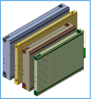
Figure 1 – The E3 family of form factors (from right to left): E3.S, E3.S 2T, E3.L, E3.L 2T
Figure 2 identifies some of the mechanical characteristics of each E3 form factor:
Device Variation | Height | Length | Width | Recommended Max Power |
E3.S | 76mm | 112.75mm | 7.5mm | 25W |
E3.S 2T | 76mm | 112.75mm | 16.8mm | 40W |
E3.L | 76mm | 142.2mm | 7.5mm | 40W |
E3.L 2T | 76mm | 142.2mm | 16.8mm | 70W |
Figure 2 – Height, length, width and recommended max power of each E3 form factor
System Design
System designers and platform architects will have more flexibility to control how the storage subsystem is constructed. Space at the front of the server can be divided and utilized more effectively because there are four unique form factors to choose from. However, most server users will likely adopt the E3.S/E3.S 2T form factors as they are compatible with the more common short-depth chassis.
The E3.S should support half of the NAND capacity of a U.2 SSD, and the E3.L should have equal NAND capacity to a U.2 SSD. This means system designers have the freedom to choose between equal capacities and nearly double the performance with a fully loaded E3.S design (Figure 3) or double the capacity and performance with a fully loaded E3.L design (Figure 4).
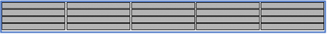
Figure 3 – 1U chassis with 20 front loading E3.S or E3.L thin devices
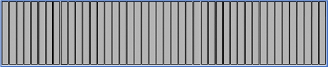
Figure 4 – 2U chassis with 44 front loading E3.S or E3.L thin devices
Furthermore, several platform challenges have been targeted with the E3 family. One challenge is the increasing amount of platform power consumed through modern CPUs, memory and GPUs. This rise in power consumption translates to a higher thermal output, which can be countered by creating effective airflow pathways for optimal cooling. A second challenge to account for is the changing role of the server storage subsystem. Future server architectures will share front-end server space, which was traditionally dedicated to storage drives, with a multitude of devices such as NVMe NAND SSDs, CXL SCM devices, accelerators, computational storage devices and front facing I/O devices. The fact that the E3 family can support multiple mechanical sizes, host link widths, and power profiles with a family of interchangeable form factors makes it an ideal choice for supporting multiple system use cases. See Figure 5 and Figure 6 below:
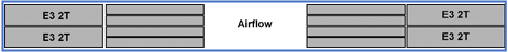
Figure 5 – Illustration of a 1U system supporting four alternate device types and eight SSD slots, while still providing enough airflow for optimal cooling
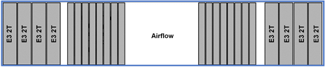
Figure 6 – Illustration of a 2U system supporting eight alternate device types and sixteen SSD slots, while still providing enough airflow for optimal cooling
Providing Value to PowerEdge Platforms
Dell Technologies is driving the adoption and standardization of the E3 family to address specific design challenges PowerEdge platforms are expected to encounter in the future:
- Increasing System Thermals - As total platform power continues to increase with the advancement of server technology the E3 form factor provides a systematic approach to platform thermal characterization as defined by the SFF-TA-1023 thermal requirements specification.
- Decreasing Physical Volume - Systems that have limited space, such as modular systems, mini- racks, and Edge platforms, have more options to better utilize the limited physical space using E3 devices.
- Higher Storage Density - Higher system storage densities can be achieved by using the denser and more efficient E3 form factors.
Conclusion
Dell Technologies is focused on standardizing the E3 family of form factors to better accommodate future technologies for optimized server solutions. Although the 2.5” U.2 flash SSD form factor is still the universal, ubiquitous form factor for most PowerEdge platforms today, the E3 family accommodates for future emerging environments by optimizing system thermals, better utilizing limited design space and increasing storage density. Furthermore, it will be compatible with PCIe Gen 5 & 6, support multiple device types and link widths, and contain various form factors that will work well in both 1U and 2U platforms.
To learn more about this Kioxia proof of concept, read the Kioxia article below:
KIOXIA Demonstrates New EDSFF SSD Form Factor Purpose-Built for Servers and Storage
Related Documents

Understanding the Value of AMDs Socket to Socket Infinity Fabric
Tue, 17 Jan 2023 00:43:22 -0000
|Read Time: 0 minutes
Summary
AMD socket-to-socket Infinity Fabric increases CPU-to-CPU transactional speeds by allowing multiple sockets to communicate directly to one another through these dedicated lanes. This DfD will explain what the socket-to-socket Infinity Fabric interconnect is, how it functions and provides value, as well as how users can gain additional value by dedicating one of the x16 lanes to be used as a PCIe bus for NVMe or GPU use.
Introduction
Prior to socket-to-socket Infinity Fabric (IF) interconnect, CPU-to-CPU communications generally took place on the HyperTransport (HT) bus for AMD platforms. Using this pathway for multi-socket servers worked well during the lifespan of HT, but developing technologies pushed for the development of a solution that would increase data transfer speeds, as well as allow for combo links.
AMD released socket-to-socket Infinity Fabric (also known as xGMI) to resolve these bottlenecks. Having dedicated IF links for direct CPU-to- CPU communications allowed for greater data-transfer speeds, so multi-socket server users could do more work in the same amount of time as before.
How Socket-to-Socket Infinity Fabric Works
IF is the external socket-to-socket interface for 2-socket servers. The architecture used for IF links is a combo of serializer/deserializer (SERDES) that can be both PCIe and xGMI, allowing for sixteen lanes per link and a lot of platform flexibility. xGMI2 is the current generation available and it has speeds that reach up to 18Gbps; which is faster than the PCIe Gen4 speed of 16Gbps. Two CPUs can be supported by these IF links. Each IF lane connects from one CPU IO die to the next, and they are interwoven in a similar fashion, directly connecting the CPUs to one- another. Most dual-socket servers have three to four IF links dedicated for CPU connections. Figure 1 depicts a high- level illustration of how socket to socket IF links connect across CPUs.
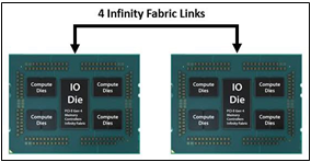
Figure 1 – 4 socket to socket IF links connect two CPUs
The Value of Infinity Fabric Interconnect
Socket to socket IF interconnect creates several advantages for PowerEdge customers:
- Dedicated IF lanes are routed directly from one CPU to the other CPU, ensuring inter-socket communications travel the shortest distance possible
- xGMI2 speeds (18Gbps) exceed the speeds of PCIe Gen4, allowing for extremely fast inter-socket data transfer speeds
Furthermore, if customers require additional PCIe lanes for peripheral components, such as NVMe or GPU drives, one of the four IF links are a cable with a connector that can be repurposed as a PCIe lane. AMD’s highly optimized and flexible link topologies enable sixteen lanes per socket of Infinity Fabric to be repurposed. This means that 2S AMD servers, such as the PowerEdge R7525, have thirty-two additional lanes giving a total of 160 PCIe lanes for peripherals. Figure 2 below illustrates what this would look like:
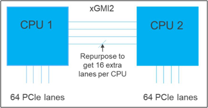
Figure 2 – Diagram showing additional PCIe lanes available in a 2S configuration
Conclusion
AMDs socket-to-socket Infinity Fabric interconnect replaced the former HyperTransport interconnect in order to allow massive amounts of data to travel fast enough to avoid speed bottlenecks. Furthermore, customers needing additional PCIe lanes can repurpose one of the four IF links for peripheral support. These advantages allow AMD PowerEdge servers, such as the R7525, to meet our server customer needs.

The Future of Server Cooling- Part 1. The History of Server and Data Center Cooling Technologies
Mon, 16 Jan 2023 18:15:45 -0000
|Read Time: 0 minutes
Summary
Today’s servers require more power than ever before. While this spike in power has led to more capable servers, it has coincidentally pushed legacy thermal hardware to its limit. The inability to support top- performance servers without liquid cooling will soon become an industry-wide challenge. We hope that by preparing our PowerEdge customers for this transition ahead of time, and explaining in detail why and when liquid cooling is necessary, they can easily adapt and get excited for the performance gains liquid cooling will enable.
Part 1 of this three part series, titled The Future of Server Cooling, covers the history of server and data center thermal technologies - which cooling methods are most commonly used, and how they evolved to enable the industry growth seen today.
The Future of Server Cooling was written because the next-generation of PowerEdge servers (and succeeding generations) may require liquid cooling assistance to enable certain (dense) configurations. Our intent is to educate customers about why the transition to liquid cooling is inevitable, and to prepare them for these changes.
Integrating liquid cooling solutions on future PowerEdge servers will allow for significant performance gains from new technologies, such as next-generation Intel® Xeon® and AMD EPYC™ CPUs, DDR5 memory, PCIe Gen5, DPUs, and more.
Part 1 of this three part series reviews some major historical cooling milestones to help explain why change has always been necessary. It also describes which technologies have evolved over time to advance to where they are today - the historical evolution of thermal technologies for both the server and the data center.
Data centers cannot exist without sufficient cooling
A data center comprises many individual pieces of technology equipment that work together collectively to support continuously running servers within a functional facility. Most of this equipment requires power to operate, which converts electrical energy into heat energy as it is used. If the heat generated grows too large, it can create undesirable thermal conditions, which can cause component and server shutdown, or even failure, if not managed properly.
Cooling technologies are implemented to manage heat build-up by moving heat away from the source (because heat cannot magically be erased) and towards a location where it is safely dispersed. This allows technology equipment within the data center to continue to work reliably and uninterrupted from the threat of shutdown from overheating. Servers from Dell Technologies can automatically adjust power consumption, but without an effective cooling solution the heat buildup within the data center would eventually exceed the capability of the server to operate, creating enormous financial losses for business.
Two areas of coverage
Cooling technologies are typically designated to two areas of coverage - directly inside of the server and at the data center floor. Most modern data centers strategically use cooling for both areas of coverage in unison.
- Cooling technologies located directly inside of the server focus on moving heat away from dense electronics that generate the bulk of it, including components such as CPUs, GPUs, memory, and more.
- Cooling technologies located at the data center floor focus on keeping the ambient room temperature cool. This ensures that the air being circulated around and within the servers is colder than the hot air they are generating, effectively cooling the racks and servers through convection.
Legacy Server Cooling Techniques
Four approaches have built upon each other over time to cool the inside of a server: conduction, convection, layout, and automation, in chronological order. Despite the advancements made to these approaches over time, the increasing thermal design power (TDP) requirements have made it commonplace to see them all working together in unison.
Conduction was the first step in server cooling evolution that allowed the earliest servers to run without overheating. Conduction directly transfers heat through surface contact. Historically, conduction cooling technologies, such as heat spreaders and heat sinks, have moved heat away from server hot spots and stored it in isolated regions where it can either reside permanently, or be transferred outside of the box through an air or liquid medium. Because heat spreaders have limited capabilities, they were rapidly replaced by heat sinks, which are the industry standard today. The most effective heat sinks are mounted directly to heat producing components with a flush base plate. As development advanced, fins of varying designs (each having unique value) were soldered to the base plate to maximize the surface area available. The base plate manufacturing process has shifted from extrusion to machine or die-cast, which reduces production time and wasted material. Material changed from solely aluminum to include copper for use cases that require its ~40% higher thermal conductivity. The following figure provides an example:
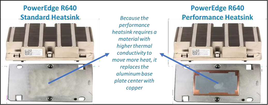
Figure 1. Heat sink base plate uses copper to support higher power
Convection cooling technologies were introduced to server architecture when conduction cooling methods could no longer solely support growing power loads. Convection transfers heat outside of the server through a medium, such as air or liquid. Convection is more efficient than conduction. When the two are used together, they form an effective system - conduction stores heat in a remote location and then convection pushes that heat out of the server.
Technologies such as fans and heat pipes are commonly used in this process. The evolution of fan technology has been extraordinary. Through significant research and development, fan manufacturers have optimized the fan depth, blade radius, blade design, and material, to present dozens of offerings for unique use cases. Factors such as the required airflow (CFM) and power/acoustic/space/cost constraints then point designers to the most appropriate fan. Variable speed fans were also introduced to control fan speeds based on internal temperatures, thereby reducing power usage. Heat pipes have also undergone various design changes to optimize efficiency. The most popular type has a copper enclosure, sintered copper wick, and cooling fluid. Today they are often embedded in the CPU heatsink base, making direct contact with the CPU, and routing that collected heat to the top of the fins in a remote heatsink.
Layout refers to the placement and positioning of the components within the server. As component power requirements increased at a faster rate than conduction and convection technologies were advancing, mechanical architects were pressed to innovate new system layout designs that would maximize the efficiency of existing cooling technologies. Some key tenets about layout design optimization have evolved over time:
- Removing obstructions in the airflow pathway
- Forming airflow channels to target heat generating components
- Balancing airflow within the server by arranging the system layout in a symmetrical fashion
Automation is a newer software approach used to enable a finer control over the server infrastructure. An autonomous infrastructure ensures that both the server components and cooling technologies are working only as hard as needed, based on workload requirements. This lowers power usage, which reduces heat output, and ultimately optimizes the intensity of surrounding cooling technologies. As previously mentioned, variable fan speeds were a cornerstone for this movement, and have been followed by some interesting innovations. Adaptive closed loop controllers have evolved to control fan speed based on thermal sensor inputs and power management inputs. Power capping capabilities ensure thermal compliance with minimum performance impact in challenging thermal conditions. For Dell PowerEdge servers, iDRAC enables users to remotely monitor and tackle thermal challenges with built-in features such as system airflow consumption, custom delta-T, custom PCIe inlet temperature, exhaust temperature control, and adjustment of PCIe airflow settings. The following figure illustrates the flow of these iDRAC automations:
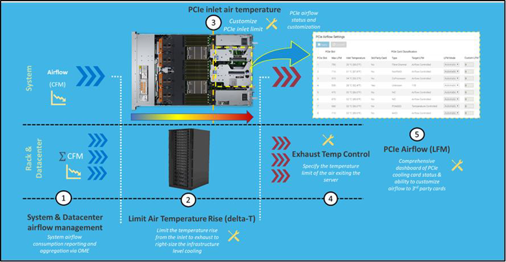
Figure 2. Thermal automations enabled by Dell proprietary iDRAC systems management
Legacy data center cooling techniques
Heat transfer through convection is rendered useless if the intake air being moved by fans is not colder than the heated air within the server. For this reason, cooling the data center room is as important as cooling the server: the two methods depend on one another. Three main approaches to data center cooling have evolved over time – raised floors, hot and cold aisles, and containment, in chronological order. Raised floors were the first approach to cooling the data center. At the very beginning, chillers, and computer room air conditioning (CRAC) units were used to push large volumes of cooled air into the datacenter, and that was enough.
However, the air distribution was wildly unorganized and chaotic, having no dedicated paths for hot or cold airflow, causing many inefficiencies such as recirculation and air stratification. Because adjustments were required to accommodate increasing power demands, the data center floor plan was redesigned to have raised floor systems with perforated tiles replacing solid tiles. This provided a secure path for the cold air created by CRAC units to stay chilled as it traveled beneath the floor until being pulled up the rack by server fans.
Hot and cold aisle rack arrangements were then implemented to assist the raised floor system when the demands of increasing heat density and efficiency could not be met. This configuration has cool air intakes and warm air exhausts facing each other at each end of a server row. Convection currents are then generated, which helped to improve airflow. However, this configuration was still unable to meet the demands of growing data center requirements, as airflow above the raised floors remained chaotic. Something else was needed to maximize efficiency.
Containment cooling ideas propagated to resolve the turbulent nature of cool and hot air mixing above raised floors. By using a physical barrier to separate cool server intake air from heated server exhaust air, operators were finally able to maintain tighter control over the airstreams. Several variants of containment exist, such as cold aisle containment and hot aisle containment, but the premise remains the same – to block cold air from mixing with hot air. Containment cooling successfully increased data center cooling efficiency, lowered energy consumption, and even created more flexibility within the data center layout (as opposed to hot and cold aisle rack arrangements, which require the racks to be aligned in a certain position). Containment cooling is commonly used today in conjunction with raised floor systems. The following figure illustrates what a hot aisle containment configuration might look like:

Figure 3. Hot aisle containment enclosure diagram, sourced from Uptime Institute
What’s Next?
Clearly the historical evolution of these thermal techniques has aided the progression of server and data center technology, enabling opportunities for innovation and business growth. Our next-generation of PowerEdge servers will see technological capabilities jump at an unprecedented magnitude, and Dell will be prepared to get our customers there with the help of our new and existing liquid cooling technologies. Part 2 of this three part series will discuss why power requirements will be rising so aggressively in our next generation PowerEdge servers, what benefits this will yield, and which liquid cooling solutions Dell will provide to keep our customers’ infrastructure cool and safe.