


SmartFabric Services Multisite Fabric Interconnect
Wed, 23 Mar 2022 16:37:35 -0000
|Read Time: 0 minutes
OS10.5.3.2 introduces the SmartFabric Services (SFS) multisite fabric interconnect. This feature enables SFS Layer 2 virtual networks to be stretched between separate SmartFabric instances (or domains) over traditional Layer 3 networks using BGP EVPN.
Up to three separate SmartFabric domains may be connected using the fabric interconnect feature. The SmartFabric domains may be in the same data center, or in physically separate sites. One instance of OpenManage Network Integration (OMNI) can be used to manage up to 15 SmartFabric domains with a single user interface.
With the multisite fabric interconnect feature, a host connected to a SmartFabric in one site and a host connected to a SmartFabric in a different site can be in the same Layer 2 network, even when separated by Layer 3 networks. This feature allows a virtual machine to be migrated from one site to another without the need to change its IP address and gateway information. It also allows SFS to support applications such as VMware vSAN stretched clusters.
This article provides an overview of the fabric interconnect feature and its configuration steps. For a detailed step-by-step deployment example, see the SmartFabric Services with Multisite vSAN Stretched Cluster Deployment Guide.
Connection options
Separate SmartFabric domains may be connected directly to each other or through existing external switches.
Direct connection option
Figure 1 shows a direct connection between SmartFabric leaf switches in two domains.
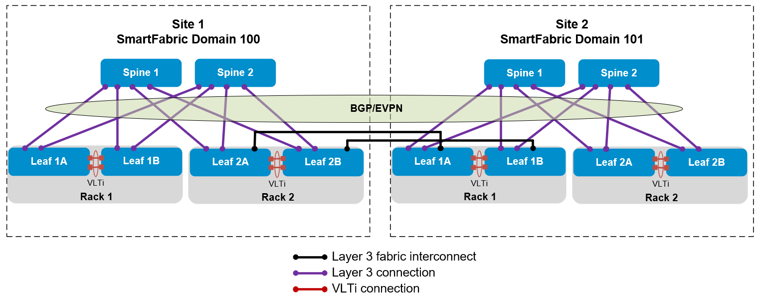
Figure 1 Direct connection between SmartFabric domains in two sites
As an option, the direct connections may be made between the spines.
External network option
Figure 2 shows two SmartFabric domains connected through an external network using the leaf switches.
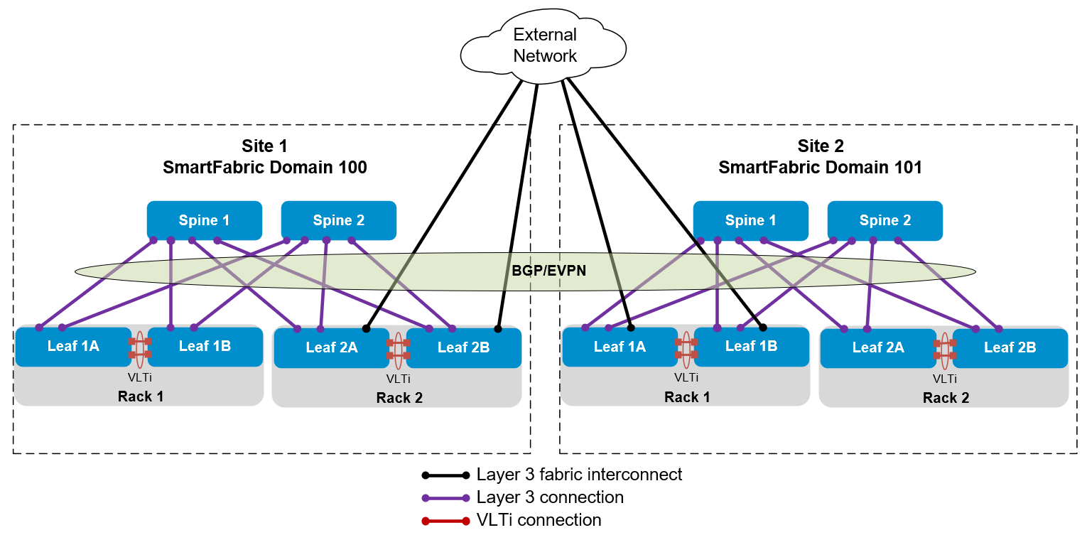
Figure 2 SmartFabric domains in two sites connected through an external network
The example covered in this article uses this topology. Optionally, the connections to the external network may be made using the spines.
SmartFabric Domain assignment
Each SmartFabric connected by a fabric interconnect to another SmartFabric must have a unique domain ID. A domain ID in the range of 100 through 107 is assigned at the time the leaf switches are placed in SmartFabric mode. (The maximum number of SmartFabric domains that may be joined using fabric interconnects is three. However, there are plans to increase this number to eight in a future OS10 release.)
If you have one SmartFabric already deployed, and did not specify a domain, its domain ID is already set to 100. The next SmartFabric created must be assigned a different domain ID if the fabric interconnect feature will be used.
The syntax to put leaf switches in SmartFabric mode is:
smartfabric l3fabric enable role LEAF vlti ethernet port_range domain domain_ID.The port_range is the range of ports used for the VLT interconnect (VLTi) between the leaf switch pair. The domain_ID is a number in the range 100 through 107. If a domain ID is not specified, it is set to 100 by default.
The syntax to put spine switches in SmartFabric mode is:
smartfabric l3fabric enable role SPINESpine switches automatically join the domain of the leaf switches they are connected to, and a domain ID is not specified in the command.
For example, the following commands are run on each leaf in the first SmartFabric domain:
OS10# configure terminal
OS10(config)# smartfabric l3fabric enable role LEAF vlti ethernet 1/1/49-1/1/52 domain 100
Reboot to change the personality? [yes/no]:y
Since Domain 100 is the default, the domain 100 portion of the SmartFabric enable command above is optional.
If Spine switches are used in the first domain, they are each placed in SmartFabric mode with the following commands:
OS10# configure terminal
smartfabric l3fabric enable role SPINE
Reboot to change the personality? [yes/no]:y
When building the second SmartFabric domain, the following commands are run on each leaf, which will be in Domain 101:
OS10# configure terminal
OS10(config)# smartfabric l3fabric enable role LEAF vlti ethernet 1/1/49-1/1/52 domain 101
Reboot to change the personality? [yes/no]:y
If Spine switches are used in the second domain, they are each placed in SmartFabric mode using the same commands as the spines in the first.
Two SmartFabric domains are now configured, one in Domain 100 and one in Domain 101. The domain ID specified determines the BGP autonomous system numbers (ASNs) and IP addresses used by default in each SmartFabric. The default SmartFabric settings for Domains 100 and 101 are shown in the following table.
| Domain ID | Leaf ASN | Spine ASN | BGP address range | VTEP address range |
|---|---|---|---|---|
100 | 65011 | 65012 | 172.16.0.0/16 | 172.30.0.0/16 |
101 | 65015 | 65016 | 172.18.0.0/16 | 172.32.0.0/16 |
You may change the ASNs and IP addresses from their defaults in the SFS UI if they conflict with the ASNs and addresses used in your existing environment.
Fabric Interconnect Configuration
Continuing with our example, SmartFabric Domain 100 is in Site 1, and SmartFabric Domain 101 is in Site 2. A pair of leaf switches in each domain connects to an external data center interconnect (DCI) switch that connects the two sites.
The external DCI switches are not part of the SmartFabric, and they have been manually configured for BGP with ASNs 65101 and 65102. The DCI switch interfaces that connect to the SmartFabric are also configured with IP addresses that will form point-to-point Layer 3 networks with the SmartFabric switches.
The SmartFabric switches are automatically configured with BGP ASNs. As shown in the previous table, leaf switches in Domain 100 use ASN 65011 by default, and leaf switches in Domain 101 use ASN 65015. Loopback addresses used as BGP router IDs are in the 172.16.0.0/16 and 172.18.0.0/16 address ranges for domains 100 and 101 respectively.
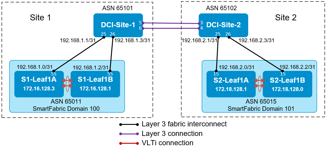
Figure 3 Fabric interconnect configuration example
The information shown in Figure 3 is used to configure the fabric interconnect in the SFS UI for each SmartFabric domain. Other leafs and spines that may be present in each SmartFabric domain are not shown. The configuration steps for this example are the same regardless of the number of switches in the two SmartFabric domains.
For Domain 100 in Site 1, the Configure MultiSite Fabric Interconnect form in the SFS UI for is filled out as shown in Figure 4.

Figure 4 Multisite Fabric Interconnect settings for Domain 100
The fields are filled out as follows:
- Switch Group - Leaf is selected since that is where the interconnect is located.
- Rack – This field is only displayed if Leaf is selected. Selecting the rack populates the lower half of form with the correct leaf pair.
- Fabric Interconnect Link – External network is selected since the connections are made through external switches.
- Peer Fabric Domain ID – 101 is the domain ID of the other fabric.
- Port – Switch service tag:Ethernet1/1/55 is the leaf port used by the fabric interconnect. It is selected from the drop-down menu.
- Local IP Address and Local Prefix Length –The IP address and prefix to be assigned to the leaf switch port are entered here.
- External ASN – 65101 is the BGP ASN configured on the external switch.
- External Interface IP – The IP address on the external switch that is on the same point-to-point network as the connected leaf switch port is entered here.
- BFD – Bi-directional Forwarding Detection (BFD) rapidly detects communication failures between two adjacent routers. As a best practice, set BFD to Enable if the external switch supports it.
- Peer BGP ASN – This field is automatically populated with the SFS default leaf ASN for Domain 101, 65015. It may be changed here if the default ASN settings for the peer domain are not used.
- Peer Loopback – The BGP loopback address for one of the two fabric interconnect leaf switches in the peer domain is entered here.
For Domain 101 in Site 2, the Configure MultiSite Fabric Interconnect page in the SFS UI is filled out in the same manner as the first domain. The completed form for Domain 101 is shown below.
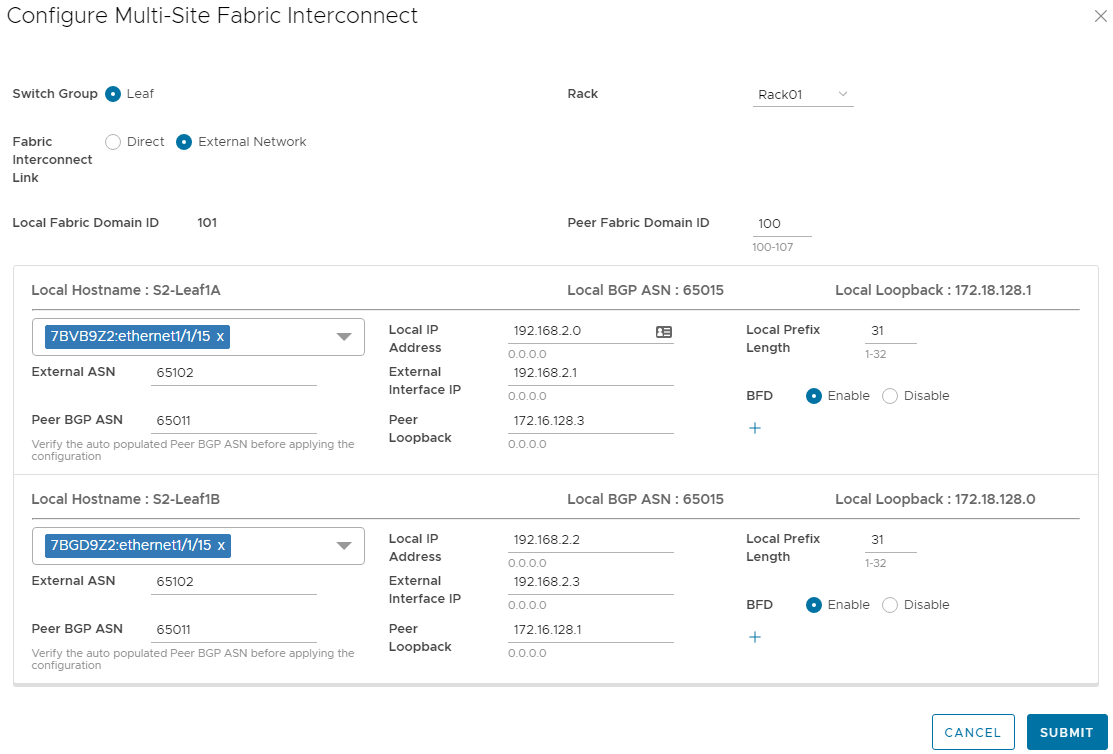
Figure 5 Multisite Fabric Interconnect settings for Domain 101
After the fabric interconnects are configured, each SmartFabric domain still has its own leader switch and SFS UI. Instead of using a separate SFS UI for each domain, use one instance of OMNI to manage up to 15 SmartFabric domains with a single user interface.
Resources
SmartFabric Services with Multisite vSAN Stretched Cluster Deployment Guide – This guide provides a step-by-step example of deploying a multisite vSAN stretched cluster in two SmartFabric domains using fabric interconnects.
Dell EMC SmartFabric Services User Guide Release 10.5.3 – The SFS user guide includes additional information about the multisite fabric interconnect feature.
OpenManage Network Integration User Guide Release 3.0 – The OMNI user guide includes information about using OMNI to manage multiple SmartFabric domains and fabric interconnect configuration with OMNI.
Dell Networking Solutions InfoHub – This site includes Dell Networking deployment guides, videos, and a support & interoperability matrix.
Related Blog Posts

New Deployment Option for SmartFabric Services with VxRail
Fri, 15 Sep 2023 20:06:45 -0000
|Read Time: 0 minutes
VxRail 7.0.400 introduces an option that opens up new functionality for SmartFabric Services (SFS) switches with VxRail deployments. This new option allows you to choose whether automated SmartFabric switch configuration is enabled or disabled during VxRail deployment.
In VxRail versions earlier than 7.0.400, automated SmartFabric switch configuration during deployment is always enabled, and there is no option to disable it. The automation configures VxRail networks on the SmartFabric switches during deployment, but it limits the ability to support SFS with VxRail in a wide range of network environments after deployment. This limitation is because internal settings specific to SFS are made to VxRail Manager which limits the ability to expand the network or add additional products in some environments.
Starting with VxRail 7.0.400, the VxRail Deployment Wizard provides an option to set Automated VxRail Switch Configuration to Disabled. Dell Technologies recommends disabling the automation, as shown below.
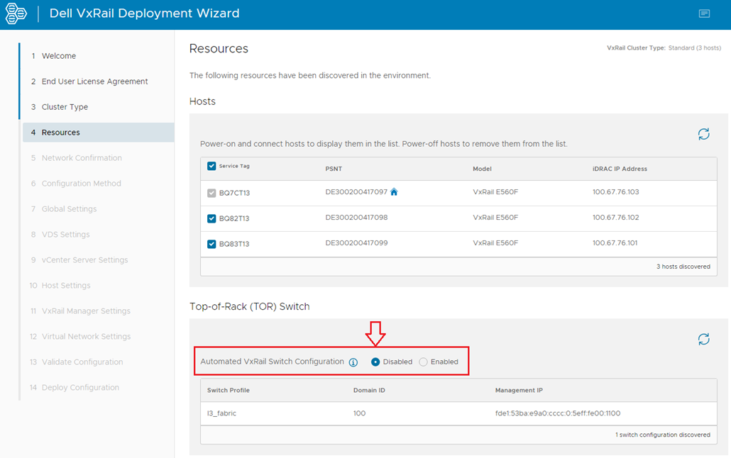
With automated switch configuration disabled, the VxRail Deployment wizard skips the switch configuration step. The advantage of bypassing this automation during deployment is that SFS and VxRail can now be supported across a wide array of network environments after deployment. It will also simplify the VxRail upgrade process in the future.
Disabling automated switch configuration only affects SmartFabric switch automation during VxRail deployment or when adding nodes to an existing VxRail cluster after deployment. The SFS UI is used to place VxRail node-connected ports in the correct networks instead of the automation.
Automated SmartFabric switch configuration after VxRail is deployed is still supported by registering the VxRail vCenter Server with OpenManage Network Integration (OMNI). When registration is done, networks that are created in vCenter continue to be automatically configured on the SmartFabric switches by OMNI.
In summary, for new deployments with SFS and VxRail 7.0.400 or later, it is recommended that you disable the automated switch configuration during deployment. This action will give you more flexibility when expanding your network in the future.
Resources
Dell Networking SmartFabric Services Deployment with VxRail 7.0.400

What’s happening with SmartFabric Services and VxRail 8.0
Fri, 15 Sep 2023 20:06:45 -0000
|Read Time: 0 minutes
This article describes the SmartFabric Services (SFS) Automated VxRail Switch Configuration feature in VxRail and explains why it was removed in VxRail 8.0.
VxRail 4.7 and 7.0 releases included Automated VxRail Switch Configuration. This feature was designed for SFS and was always enabled. It automatically configured VxRail networks on SmartFabric switches during VxRail deployment. However, this integration prevented the ability to support SFS with VxRail in some network environments, such as with a vSAN stretched cluster or VMware Cloud Foundation.
Starting in VxRail 7.0.400, the option to manually disable Automated VxRail Switch Configuration was added to the VxRail deployment wizard, as shown below.
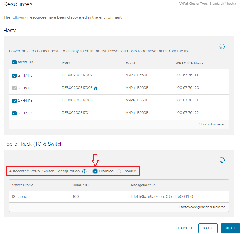 Figure 1 VxRail 7.0.400 deployment wizard resources page
This option is described in New Deployment Option for SmartFabric Services with VxRail, and is present in VxRail 7.0.400 and later VxRail 7.x releases. If Automated VxRail Switch Configuration is set to Disabled during VxRail deployment as recommended, SFS can be supported in other network environments.
Starting in VxRail 8.0, the Top-of-Rack (TOR) Switch section in the VxRail deployment wizard has been removed as shown below.
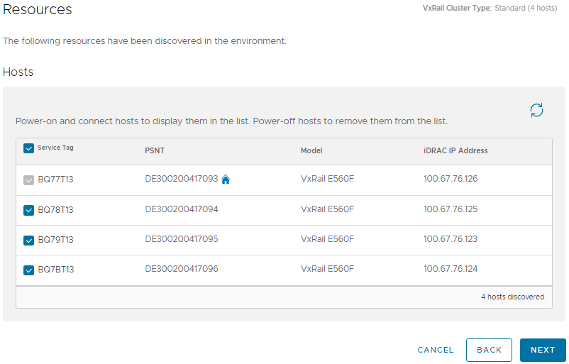 Figure 2 VxRail 8.0 deployment wizard resources page
Automated VxRail Switch Configuration is automatically disabled in VxRail 8.0. Disabling this feature ensures that new SFS with VxRail installations are supported in other network environments.
Disabling automated switch configuration only affects SmartFabric switch automation during VxRail deployment or when adding VxRail nodes to an existing cluster after deployment. With the feature disabled, you will use the SFS UI to place VxRail node-connected ports in the correct networks instead of the automation.
You can still configure SmartFabric switches automatically after VxRail deployment by registering the VxRail vCenter Server with OpenManage Network Integration (OMNI). When registration is complete, networks created in vCenter continue to be automatically configured on the SmartFabric switches using OMNI.
The Dell Networking SmartFabric Services Deployment with VxRail 7.0.400 deployment guide still applies to VxRail 8.0 deployments. The only difference is the Resources page of the VxRail deployment wizard will look like Figure 2 instead of Figure 1.
Resources
Dell Networking SmartFabric Services Deployment with VxRail 7.0.400
New Deployment Option for SmartFabric Services with VxRail