


Routing on the Host - Essential to the Scalable Data Center
Tue, 13 Dec 2022 18:04:10 -0000
|Read Time: 0 minutes
Routing on the Host (RoH) is a natural next step for data center operators who have adopted IP BGP in their switch stacks. They have adapted the pure Layer 3 fabric pioneered by web-scale operators to work in their networks. Border Gateway Protocol (BGP) has proven to be the ideal routing protocol for the IP fabric because it is mature, ubiquitous, and feature rich. The next step is to implement RoH and use IP BGP in the connection from the server (host) interface to the leaf switch port, where the rubber hits the road.
BGP can be simplified by developing a suitable routing protocol design and establishing standard configuration patterns to enact the design. All personnel involved with configuration must understand how BGP works and is configured. Dell data center switches running Dell SmartFabric OS10 provide a robust platform to run RoH with a Layer 3 BGP fabric.
In this blog, we consider benefits of RoH, including improved scalability, flexibility, and performance with some use cases. For additional details about RoH, also known as routing to the host, see the blog Do I Need Layer 2 Switching?.
Figure 1 illustrates RoH with BGP. This example consists of a Dell switch fabric running Dell SmartFabric OS10 configured for Layer 3 point-to-point links and exterior BGP as the routing protocol. The host is a server with a bare metal installation of Linux. The host is running FRRouting (FRR), an open-source routing stack configured for BGP. Note that the host and switch ports are only configured for Layer 3 BGP networking.
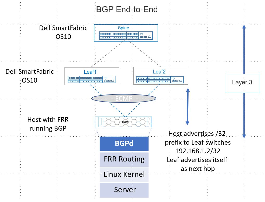
Figure 1. Routing to the Host Supported by Dell SmartFabric OS10 BGP
Scalability
A data center design must facilitate scaling out (horizontally) to accommodate additional workloads quickly and with minimal impact on network operations. Routing on the host facilitates scaling out.
Consider a use case of a customer with a multi-site data center in Figure 2 on the right. Operations requires scaling out compute (horizontally) to increase website capacity. Site 1 is resource-constrained, meaning Spine 4, Leaf 7 and Leaf 8, and associated hosts will be added to Site 2. The hosts and leaf switch ports to the hosts will be configured for Layer 3 BGP. At cutover, the switches communicate via BGP, and new routes converge. The new hosts advertise their presence using BGP. The whole network becomes aware of the new hosts and the applications can now run. Routing to the host and BGP has enabled a quick scale-out. The retirement of hosts can also happen with minimal effects through BGP convergence.
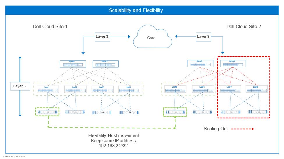
Figure 2. Scalability and flexibility
Flexibility
RoH also enhances flexibility by enabling subnet freedom for hosts across the IP fabric. Hosts can be redeployed anywhere and keep the same IP addresses. The IP fabric uses BGP to communicate new routes to the host. This can be compared with the standard of configuring Layers 2 and 3 at the leaf-host interface. Hosts are bound to the leaf switches per rack. Migration of the host while keeping the same IP address is possible but requires additional extended VLAN configuration.
Figure 2 illustrates the flexibility RoH offers with a use case. The customer must move a host from Site 1 to Site 2. The host IP address must not be changed to prevent breaking associated applications. The host operating system and applications are moved to Site 2 by the preferred method. When the host comes up, it advertises its /32 route prefix (192.168.2.2/32) to the leaf switches, and the route is propagated throughout with BGP. The switch’s routing information base (RIB) and forwarding information base (FIB) tables are updated by BGP with the route to the host.
Increased switch performance
RoH can also increase performance by reducing latency at the host-to-leaf boundary. Each Dell data center switch has a high-performance network processing unit (NPU) at its core that empowers the rich set of network capabilities available with Dell data center switches running Dell SmartFabric OS10.
The NPU has internal pipelines that handle ingress and egress packet processing for each port based on how the switch is configured by the user.
The number of features enabled at Layer 2 and Layer 3 can affect latency through the switch, as shown in Figure 4. With the traditional Layer 2 and Layer 3 hybrid connection from switch to host, the NPU must process packets at Layer 2 such as VLAN assignment, LAG, and STP operations. It also performs Layer 3 functions like maintaining IP host tables, the RIB, and the FIB.
Layer 3 BGP End-to-End is configured between the switch ports and the host. Layer 2 packet processing is not performed because only Layer 3 is used. This can decrease latency from port to port compared with configuring Layer 2 and Layer 3 on the switch port as traditionally done. The simplicity of RoH can increase performance and simplify host and network configuration tasks.
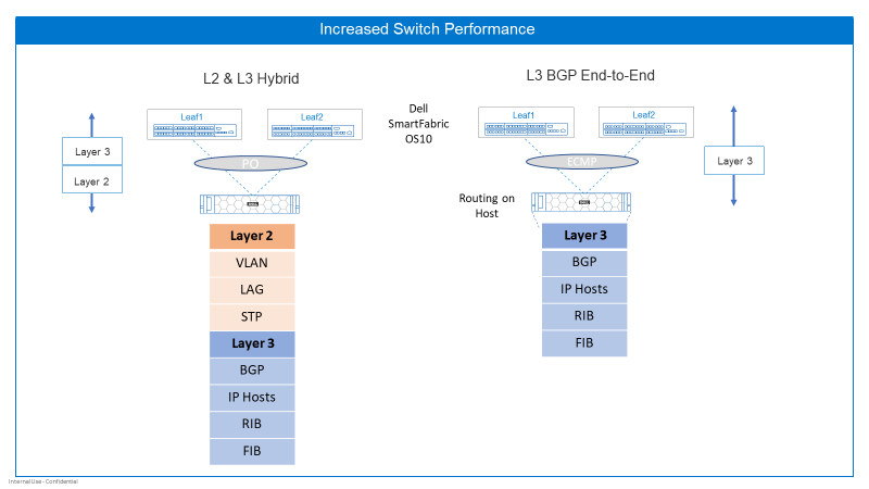
Figure 3. Increased switch performance
In summary, enabling RoH with Dell SmartFabric OS10:
- Enhances scalability in and out: Hosts can be added or removed with minimal reconfiguration.
- Enables you to move hosts around and keep the same IP address: BGP enables the network to learn the best route to the host no matter where it’s hiding.
- Simplifies the protocol stack: There is less protocol overhead and less to configure on the host and switch.
Related blogs
Related Blog Posts

Be more agile with EVPN Multihoming (MH)
Thu, 04 Jan 2024 16:51:10 -0000
|Read Time: 0 minutes
Let’s talk about enhancing your basic EVPN fabric. In your typical data center EVPN fabric, an end host uses dual homed connections onto the leaf or Top of Rack (ToR) switches.
The ToRs are usually a pair of switches configured with multi-chassis link aggregation (MC-LAG) to provide end-host link redundancy if one of the ToRs failed.
These links are Layer 2 with spanning-tree deployed on the fabric. Spanning tree typically blocks half of the links to avoid any network loops. As a result, the fabric bandwidth is cut in half. This only happens when the LAG consists of single links, as demonstrated in Figure 2.
However, if there was a way to attain link redundancy, flexibility, and full link bandwidth utilization things could be more interesting in the EVPN landscape.
Dell Enterprise SONiC 4.2 brings EVPN multihoming into the data center. It is a standards-based replacement for multi-chassis link aggregation (Multi-chassis Link Aggregation Group) and legacy stacking technology.
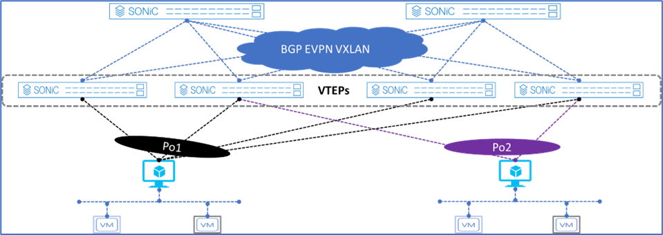
Figure 1. Dell Enterprise SONiC EVPN MH
Figure 1 shows the supported Dell Enterprise SONiC EVPN MH deployment. It shows the maximum number of VTEPs that can be connected to a single end host.
These connections are independent, meaning each link belonging to the link aggregation (LAG) can be connected to multiple independent upstream switches and these upstream switches do not have to be interconnected.
Deployment simplicity is the main benefit of EVPN MH, as all the connections only have to be connected from the end-host or server to the switches.
Achieve end host enhanced connectivity and link efficiency with EVPN MH
In an EVPN fabric, especially a data center fabric, the end hosts or servers are dual homed to a pair of Top of Rack (ToR) switches providing link redundancy. This deployment is common and it uses MC-LAG.
The other deployment option is known as stacking. This option involves several switches stacked together with a primary switch acting as the controller of the stack. All end-hosts or servers are connected to each of the switches part of the stack.
Note: A stack consisting of a single switch is also possible, but rarely deployed.
Both deployments offer link and device redundancy, but they have some limitations that EVPN MH can overcome. The benefits and limitations for each deployment option are described in the following lists.
MC-LAG deployment
- A minimum of two ToR/Leaf switches are required
- A single switch deployment is not supported
- An end host or server can connect only up to two ToRs/Leaf switches at any given time
- All connections from the end-host or server are Layer 2 based
Stacking deployment
- A maximum of eight switches are stacked with one primary or controller switch
- Specific types of stacking cables are required to form the stack
- A single switch deployment is not supported
- All end hosts or servers connect to each switch part of the stack to maintain link redundancy, resulting in a cable management situation
- All connections from the end-host or server are Layer 2 based
EVPN multihoming deployment
- A minimum of one ToR/Leaf switch is required
- An end-host or server can connect to four separate ToR/Leaf switches (VTEPs) at any given time
- All links from the end-host or server to the VTEPs are active
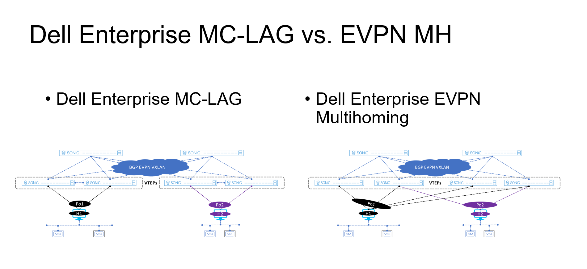
Figure 2. MC-LAG vs. EVPN multihoming deployment
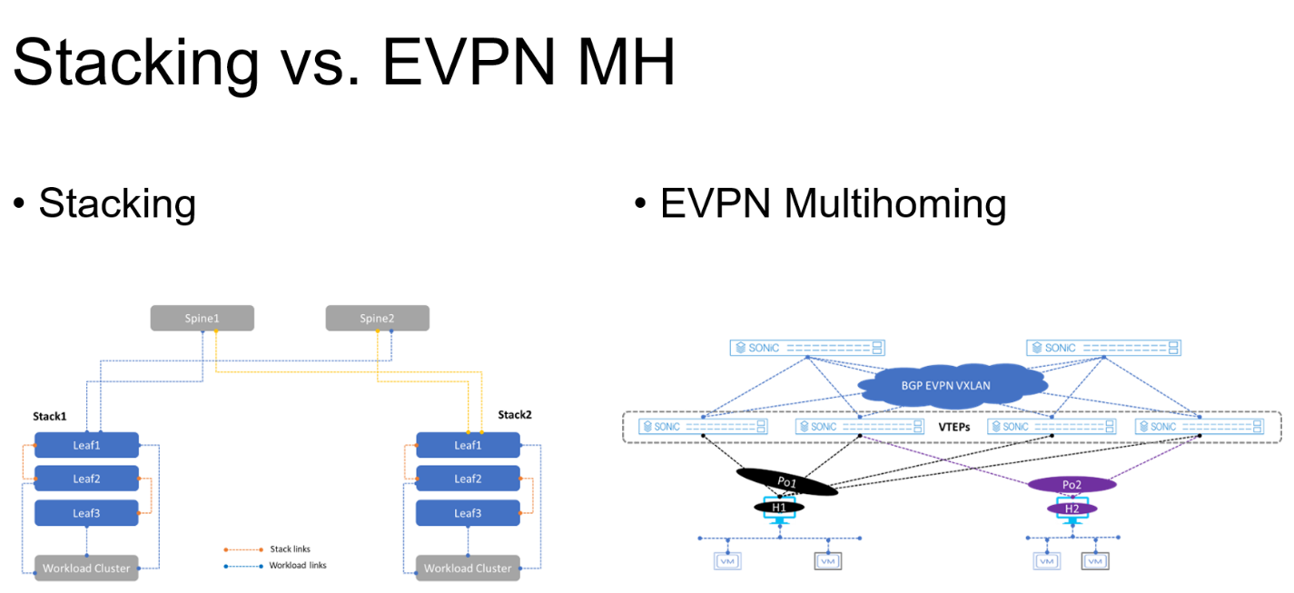
Figure 3. Stacking vs. EVPN multihoming deployment
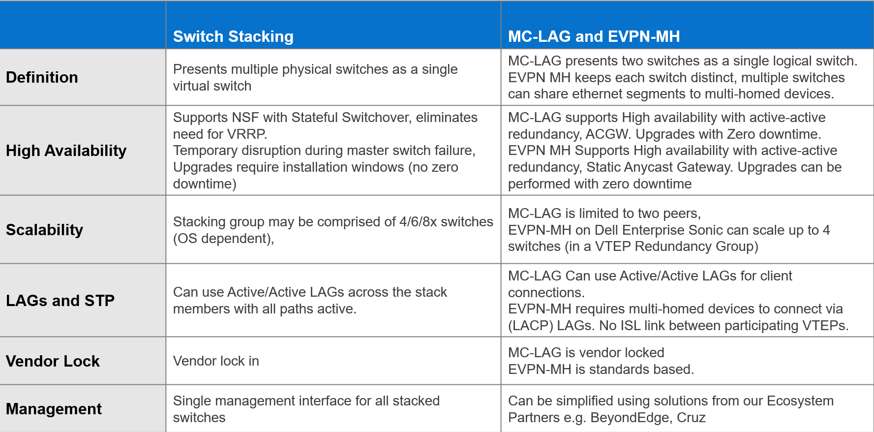
The advantages offered by EVPN multihoming are clear when compared with the traditional stacking and MC-LAG. Table 1 summarizes these differences.
Table 1. Stacking compared to MC-LAG and EVPN-MH
EVPN offers an upgrade to the legacy Layer 2 VPN technology. EVPN should be considered each time a new fabric is deployed, especially when virtualization is one of the workloads.
Dell Enterprise SONiC 4.2 offers even more simplicity into the adoption of EVPN in the data center.
Additional resources
Dell Enterprise SONiC 4.2.0 User Guide (log in required)

Virtualization with Layer 2 over Layer 3
Tue, 28 Mar 2023 12:49:05 -0000
|Read Time: 0 minutes
IT organizations must transform to meet the increasingly complex challenges in data center networking. Virtualization and software-defined data center (SDDC) in hyperconverged services are key components for today's data centers.
IT organizations making this transformation must interconnect their data centers. Virtualization and other high-value services are creating the need for logically connected, geographically isolated data centers. Dell Technologies has the infrastructure architectures to facilitate these requirements.
With Dell SmartFabric OS10 operating system, Dell introduces a networking solution in virtualization with two popular VLAN tunneling technologies: virtual extensive LAN (VXLAN) and generic routing encapsulation (GRE).
The solution of Border Gateway Protocol (BGP) and Ethernet Virtual Private Network (EVPN) for VXLAN uses Dell PowerSwitches and PowerEdge servers. BGP EVPN for VXLAN serves as a network virtualization overlay to extend Layer 2 connectivity across the data centers, which simplifies the deployment of virtualization and provides benefits such as vMotion, vSAN, and overall efficient resource sharing.
Figure 1. BGP EVPN for VXLAN network diagram overview
GRE is an IP encapsulation protocol that transports IP packets over a network in a point-to-point interconnection between two branches by tunneling any Layer 3 protocol, including IP.
With BGP EVPN VXLAN and GRE, any organization can interconnect their data centers across public internet in a secure (encrypted) manner. For example, data centers can securely connect over a local connection network—even if they are geographically distant or in different countries. The following figure illustrates that changing the infrastructure to leverage the existing Dell products portfolio on the production environment (VxRail, PowerStore, and PowerFlex) does not impact performance.
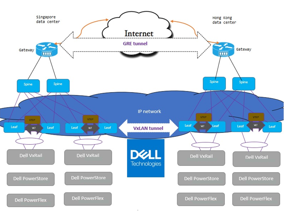
Figure 2. Data center interconnection over public internet with BGP EVPN for VXLAN and GRE tunneling
BGP EVPN for VXLAN and GRE tunneling provides the following benefits:
- Increases scalability in virtualized cloud environments
- Optimizes existing infrastructure with virtualization, scalability, flexibility, and mobility across data centers
- Maintains the security of the data center
Contact Dell Technologies for more details on this solution. Dell Technologies is excited to partner with you to deliver high-value services for your business.
Resources
For more information, refer to the following sections of the VMware Cloud Foundation on VxRail Multirack Deployment Using BGP EVPN Configuration and Deployment Guide: