


PowerFlex: The advantages of disaggregated infrastructure deployments
Mon, 17 Aug 2020 21:39:26 -0000
|Read Time: 0 minutes
For several years, there has been a big push from quite a number of IT vendors towards delivering solutions based on Hyperconverged Infrastructure or HCI. The general concept of HCI is to take the three primary components of IT, compute, network and storage, and deliver them in a software defined format within a building block, normally an x86 based server. These building blocks are then joined together to create a larger, more resilient environment. The software defined components are typically a hypervisor to provide compute, virtual adapters and switches for networking, along with some software that takes the local disks attached to the server, combines them with the disks directly attached to the other building blocks and presents them as a virtual storage system back to the environment.
The HCI approach is attractive to customers for a variety of reasons:
- Easy upgrades by just adding in another building block
- A single management interface for virtual compute, virtual networking and virtual storage
- Having one team to manage everything as it is all in one place
There are of course scenarios where the HCI model does not fit, the limitations are frequently associated with the software defined storage part of the environment, situations such as the following:
- Extra storage is required but additional compute and the associated licensing is not.
- Paying for database licensing on cores that are being used for virtual storage processes.
- Unused storage capacity within the HCI environment that is inaccessible to servers outside the HCI environment.
- A server requirement for a specific workload that does not match the building blocks deployed.
- When maintenance is required it impacts both compute and storage.
Several HCI vendors have attempted to address these points but often their solutions to the issues involve a compromise.
What if there was a solution that provided software defined storage that was flexible enough to meet these requirements without compromise?
Step forward PowerFlex, a product flexible enough to be deployed as an HCI architecture, a disaggregated architecture (separate compute and storage layers managed within the same fabric), or a mixture of the two.
So how can PowerFlex be this flexible?
It is all about how the product was initially designed and developed, it consists predominantly of three separate software components:
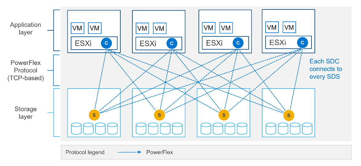
- Storage Data Client (SDC): The software component installed on the operating system that will consume storage. It can be thought of as analogous to a Fibre Channel adapter driver from the days of SAN interconnect storage arrays. It can be installed on a wide selection of operating systems and hypervisors, most Linux distributions, VMware and Windows are supported.
- Storage Data Server (SDS): The component that is installed on the server or virtual server providing local disk capacity, it works with other servers installed with the SDS software to provide a pool of storage from which volumes are allocated. It is generally installed on a Linux platform.
- Metadata Manager (MDM): The software management component, it ensures that SDC and the SDS components are behaving themselves and playing nicely together (parents of more than one child will understand).
Each of these components can be installed across a cluster of servers in a variety of ways in order to create flexible deployment scenarios. The SDC and SDS components communicate with one another over a standard TCP/IP network to form an intelligent fabric, this is all overseen by the MDM, which is not in the data path.
Some pictures will help illustrate this far better than I can with words.
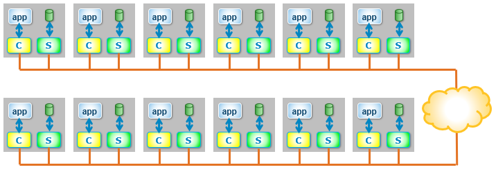
By installing the SDC (the C in a yellow box) and the SDS (the S in a green box) on to the same server, an HCI environment is created.
If the SDC and SDS are installed on dedicated servers, a disaggregated infrastructure is created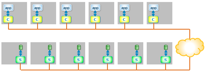
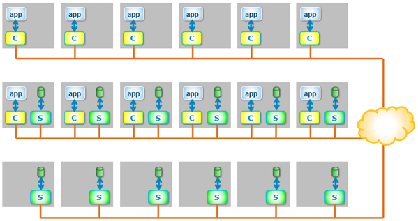
And because PowerFlex is entirely flexible (the clue is in the name), HCI and disaggregated architectures can be mixed within the same environment.
What are the advantages of deploying a disaggregated environment?
- MAXIMUM FLEXIBILITY - Compute and storage resources can be scaled independently.
- CLOUD-LIKE ECONOMICS – following on from above – what if an application needs to cope with a sudden doubling of compute resource (for example, to cope with a one-off business event)? With a disaggregated deployment, the extra compute-only resources can be added temporarily into the environment, ride the peak demand, then retire afterwards, reducing expenditure by only using what is needed.
- MAXIMISE STORAGE UTILISATION - Completely heterogeneous environments can share the same storage pool.
- CHOOSE THE CORRECT CPU FOR THE WORKLOAD - Servers with frequency optimised processors can be deployed for database use and not require licenses for cores potentially performing processing related to storage.
- AVOID CREATING MULTIPLE ISLANDS OF SOFTWARE DEFINED STORAGE - A mixture of hypervisors and operating systems can be deployed within the same environment; VMware, Hyper-V and Red Hat Virtualisation, along with operating systems running on bare metal hardware, all accessing the same storage.
- UPDATE STORAGE & COMPUTE INDEPENDENTLY - Maintenance can be performed on storage nodes completely independently of compute nodes and vice versa, thereby simplifying planned downtime. This can dramatically simplify operations, especially on larger clusters and prevents storage and compute operators from accidentally treading on each other’s toes!
Whilst HCI deployments are ideal for environments where compute requirements and storage capacity increases remain in lockstep, there are many use cases where compute and storage needs grow independently, PowerFlex is capable of serving both requirements.
PowerFlex was built to allow this disaggregation of resources from day one, which means that there is no downside to performance or capacity when storage nodes are added to existing clusters, in fact there are only positives, with increased performance, capacity and resilience, setting PowerFlex apart from many other software defined storage products.
Related Blog Posts

Introducing NVMe over TCP (NVMe/TCP) in PowerFlex 4.0

Fri, 26 Aug 2022 18:59:38 -0000
|Read Time: 0 minutes
Anyone who has used or managed PowerFlex knows that an environment is built from three lightweight software components: the MDM, the SDS, and the SDC. To deploy a PowerFlex environment, the typical steps are:
- Deploy an MDM management cluster
- Create a cluster of storage servers by installing and configuring the SDS software component
- Add Protection Domains and Storage Pools
- Install the SDC onto client systems
- Provision volumes and away you go!!*
*No requirement for multipath software, this is all handled by the SDC/SDS
There have been additions to this over the years, such as an SDR component for replication and the configuration of NVDIMM devices to create finegranularity storage pools that provide compression. Also added are PowerFlex rack and appliance environments. This is all automated with PowerFlex Manager. Fundamentally, the process involves the basic steps outlined above.
So, the question is why would we want to change anything from an elegant solution that is so simple?
This is due to where the SDC component ‘lives’ in the operating system or hypervisor hosting the application layer. Referring to the diagram below, it shows that the SDC must be installed in the kernel of the operating system or hypervisor, meaning that the SDC and the kernel must be compatible. Also the SDC component must be installed and maintained, it does not just ‘exist’.
In most cases, this is fine and there are no issues whatsoever. The PowerFlex development team keeps the SDC current with all the major operating system versions and customers are happy to update the SDC within their environment when new versions become available.
There are, however, certain cases where manual deployment and management of the SDC causes significant overhead. There are also some edge use cases where there is no SDC available for specific operating systems. This is why the PowerFlex team has investigated alternatives.
In recent years, the use of Non-Volatile Memory Express (NVMe) has become pervasive within the storage industry. It is seen as the natural replacement to SCSI, due to its simplified command structure and its ability to provide multiple queues to devices, aligning perfectly with modern multi-core processors to provide very high performance.
NVMe appeared initially as a connection directly to disks within a server over a PCIe connection, progressing to being used over a variety of fabric interconnects.
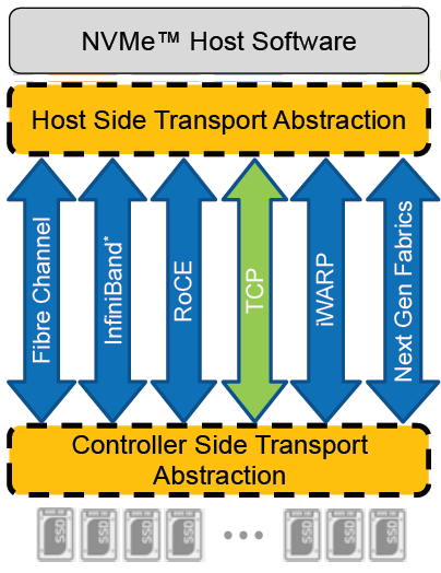
Added to this is the widespread support for NVMe/TCP across numerous operating system and hypervisor vendors. Most include support natively in their kernels.
There have been several announcements by Dell Technologies over the past months highlighting NVMe/TCP as an alternative interconnect to iSCSI across several of the storage platforms within the portfolio. It is therefore a natural progression for PowerFlex to also provide support for NVMe/TCP, particularly because it already uses a TCP-based interconnect.
PowerFlex implements support for NVMe/TCP with the introduction of a new component installed in the storage layer called the SDT.
The SDT is installed at the storage layer. The NVMe initiator in the operating system or hypervisor communicates with the SDT, which then communicates with the SDS. The NVMe initiator is part of the kernel of the operating system or hypervisor.
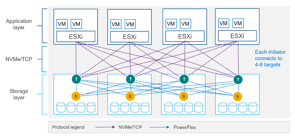
Of course, because PowerFlex is so ‘flexible,’ both connection methods (SDC and NVMe/TCP) are supported at the same time. The only limitation is that a volume can only be presented using one protocol or the other.
For the initial PowerFlex 4.0 release, the VMware ESXi hypervisor is supported. This support starts with ESXi 7.0 U3f. Support for Linux TCP initiators is currently in “tech preview” as the initiators continue to grow and mature, allowing for all failure cases to be accounted for.
NVMe/TCP is a very powerful solution for the workloads that take advantage of it. If you are interested in discovering more about how PowerFlex can enhance your datacenter, reach out to your Dell representative.
Authors:
Kevin M Jones, PowerFlex Engineering Technologist.
Tony Foster, Senior Principal Technical Marketing Engineer.
Twitter: @wonder_nerd
LinkedIn

Q1 2024 Update for Terraform Integrations with Dell Infrastructure

Tue, 02 Apr 2024 14:45:56 -0000
|Read Time: 0 minutes
This post covers all the new Terraform resources and data sources that have been released in the last two quarters: Q4’23 and Q1 ‘24. You can check out previous releases of Terraform providers here: Q1-2023, Q2-2023, and Q3-2023. I also covered the first release of PowerScale provider here.
Here is a summary of the Dell Terraform Provider versions released over the last two quarters:
- v1.1 and v1.2 of the provider for PowerScale
- v1.3 and v1.4 of the provider for PowerFlex
- v1.3 and v1.4 of the provider for PowerStore
- v1.2 of the Provider for OME
- v1.1 and v1.2 of the Provider for Redfish
PowerScale Provider v1.1 and v1.2
PowerScale received the most number of new Terraform capabilities in the last few months. New resources and corresponding data sources have been under the following workflow categories:
- Data Management
- User and Access Management
- Cluster Management
Data management
Following is the summary for the different resource-datasource pairs introduced to automate operations related to Data management on PowerScale:
Snapshots: CRUD operations for Snapshots
Here's an example of how to create a snapshot resource within a PowerScale storage environment using Terraform:
resource "powerscale_snapshot" "example_snapshot" {
  name        = "example-snapshot"
  filesystem  = powerscale_filesystem.example_fs.id
  description = "Example snapshot description"
  // Add any additional configurations as needed
}- name: Specifies the name of the snapshot to be created.
- filesystem: References the PowerScale filesystem for which the snapshot will be created.
- description: Provides a description for the snapshot.
Here's an example of how to retrieve information about existing snapshots within a PowerScale environment using Terraform:
data "powerscale_snapshot" "existing_snapshot" {
  name = "existing-snapshot"
}

output "snapshot_id" {
  value = data.powerscale_snapshot.existing_snapshot.id
}- name: Specifies the name of the existing snapshot to query.
Snapshot schedules: CRUD operations for Snapshot schedules
Following is an example of how to define a snapshot schedule resource:
resource "powerscale_snapshot_schedule" "example_schedule" {
  name                = "example-schedule"
  filesystem          = powerscale_filesystem.example_fs.id
  snapshot_type       = "weekly"
  retention_policy    = "4 weeks"
  snapshot_start_time = "23:00"
  // Add any additional configurations as needed
}- name: Specifies the name of the snapshot schedule.
- filesystem: References the PowerScale filesystem for which the snapshot schedule will be applied.
- snapshot_type: Specifies the type of snapshot schedule, such as "daily", "weekly", and so on.
- retention_policy: Defines the retention policy for the snapshots created by the schedule.
- snapshot_start_time: Specifies the time at which the snapshot creation process should begin.
Data Source Example:
The following example shows how to retrieve information about existing snapshot schedules within a PowerScale environment using Terraform. The powerscale_snapshot_schedule data source fetches information about the specified snapshot schedule. An output is defined to display the ID of the retrieved snapshot schedule:
data "powerscale_snapshot_schedule" "existing_schedule" {
  name = "existing-schedule"
}

output "schedule_id" {
  value = data.powerscale_snapshot_schedule.existing_schedule.id
}- name: Specifies the name of the existing snapshot schedule to query.
File Pool Policies: CRUD operations for File Pool Policies
File policies in PowerScale help establish policy-based workflows like file placement and tiering of files that match certain criteria. Following is an example of how the new file pool policy resource can be configured:
resource "powerscale_filepool_policy" "example_filepool_policy" {
  name = "filePoolPolicySample"
  is_default_policy = false

  file_matching_pattern = {
    or_criteria = [
      {
        and_criteria = [

          {
            operator = ">"
            type     = "size"
            units    = "B"
            value    = "1073741824"
          },
          {
            operator          = ">"
            type              = "birth_time"
             use_relative_time = true
            value             = "20"
          },
          {
            operator          = ">"
            type              = "metadata_changed_time"
             use_relative_time = false
            value             = "1704742200"
          },
          {
            operator          = "<"
            type              = "accessed_time"
             use_relative_time = true
            value             = "20"
          }
        ]
      },
      {
        and_criteria = [
          {
            operator          = "<"
            type              = "changed_time"
             use_relative_time = false
            value             = "1704820500"
          },
          {
             attribute_exists = false
            field            = "test"
            type             = "custom_attribute"
            value            = ""
          },
          {
            operator = "!="
            type     = "file_type"
            value    = "directory"
          },
          {
             begins_with    = false
            case_sensitive = true
            operator       = "!="
            type           = "path"
            value          = "test"
          },
          {
            case_sensitive = true
            operator       = "!="
            type           = "name"
            value          = "test"
          }
        ]
      }
    ]
  }
  # A list of actions to be taken for matching files. (Update Supported)
  actions = [

    {
       data_access_pattern_action = "concurrency"
      action_type                = "set_data_access_pattern"
    },
    {
       data_storage_policy_action = {
        ssd_strategy = "metadata"
        storagepool  = "anywhere"
      }
      action_type = "apply_data_storage_policy"
    },
    {
       snapshot_storage_policy_action = {
        ssd_strategy = "metadata"
        storagepool  = "anywhere"
      }
      action_type = "apply_snapshot_storage_policy"
    },
    {
       requested_protection_action = "default"
      action_type                 = "set_requested_protection"
    },
    {
       enable_coalescer_action = true
      action_type             = "enable_coalescer"
    },
    {
      enable_packing_action = true,
      action_type           = "enable_packing"
    },
    {
      action_type = "set_cloudpool_policy"
       cloudpool_policy_action = {
         archive_snapshot_files = true
        cache = {
          expiration = 86400
          read_ahead = "partial"
          type       = "cached"
        }
        compression                  = true
        data_retention               = 604800
        encryption                   = true
         full_backup_retention        = 145152000
         incremental_backup_retention = 145152000
        pool                         = "cloudPool_policy"
         writeback_frequency          = 32400
      }
    }
  ]

  description = "filePoolPolicySample description"

  apply_order = 1
}
You can import existing file pool policies using the file pool policy ID:
terraform import powerscale_filepool_policy.example_filepool_policy <policyID>
or by simply referencing the default policy:
terraform import powerscale_filepool_policy.example_filepool_policy is_default_policy=true
The data source can be used to get a handle to a particular file pool policy:
data "powerscale_filepool_policy" "example_filepool_policy" {
  filter {
    # Optional list of names to filter upon
    names = ["filePoolPolicySample", "Default policy"]
  }
}
or to get the complete list of policies including the default policy:
data "powerscale_filepool_policy" "all" {
}
You can then deference into the data structure as needed.
User and Access management
Following is a summary of the different resource-datasource pairs introduced to automate operations related to User and Access management on PowerScale:
LDAP Providers: CRUD operations
To create and manage LDAP providers, you can use the new resource as follows:
resource "powerscale_ldap_provider" "example_ldap_provider" {
  # Required params for creating and updating.
  name = "ldap_provider_test"
  # root of the tree in which to search identities.
  base_dn = "dc=tthe,dc=testLdap,dc=com"
  # Specifies the server URIs. Begin URIs with ldap:// or ldaps://
  server_uris = ["ldap://10.225.108.54"]
}
You can import existing LDAP providers using the provider name:
terraform import powerscale_ldap_provider.example_ldap_provider <ldapProviderName>
and also get a handle using the corresponding data source using a variety of criteria:
data "powerscale_ldap_provider" "example_ldap_provider" {
  filter {
    names = ["ldap_provider_name"]
    # If specified as "effective" or not specified, all fields are returned. If specified as "user", only fields with non-default values are shown. If specified as "default", the original values are returned.
    scope = "effective"
  }
}
ACL Settings: CRUD operations
PowerScale OneFS provides very powerful ACL capabilities, including a single namespace for multi-protocol access and its own internal ACL representation to perform access control. The internal ACL is presented as protocol-specific views of permissions so that NFS exports display POSIX mode bits for NFSv3 and shows ACL for NFSv4 and SMB. Now, we have a new resource to manage the global ACL settings for a given cluster:
resource "powerscale_aclsettings" "example_acl_settings" {
  # Optional fields both for creating and updating
  # Please check the acceptable inputs for each setting in the documentation
  #     access                  = "windows"
  #     calcmode                = "approx"
  #     calcmode_group          = "group_aces"
  #     calcmode_owner          = "owner_aces"
  #     calcmode_traverse       = "ignore"
  #     chmod                   = "merge"
  #     chmod_007               = "default"
  #     chmod_inheritable       = "no"
  #     chown                   = "owner_group_and_acl"
  #     create_over_smb         = "allow"
  #     dos_attr                = "deny_smb"
  #     group_owner_inheritance = "creator"
  #     rwx                     = "retain"
  #     synthetic_denies        = "remove"
  #     utimes                  = "only_owner"
}
Import is supported, and there is corresponding data source for the resource as well.
Smart Quotas: CRUD operations
Following is an example that shows how to define a quota resource:
resource "powerscale_quota" "example_quota" {
  name         = "example-quota"
  filesystem   = powerscale_filesystem.example_fs.id
  size         = "10GB"
  soft_limit   = "8GB"
  hard_limit   = "12GB"
  grace_period = "7d"
  // Add any additional configurations as needed
}- name: Specifies the name of the quota.
- filesystem: References the PowerScale filesystem to associate with the quota.
- size: Sets the size of the quota.
- soft_limit: Defines the soft limit for the quota.
- hard_limit: Defines the hard limit for the quota.
- grace_period: Specifies the grace period for the quota.
Data Source Example:
The following code snippet illustrates how to retrieve information about existing smart quotas within a PowerScale environment using Terraform. The powerscale_quota data source fetches information about the specified quota. An output is defined to display the ID of the retrieved quota:
data "powerscale_quota" "existing_quota" {
  name = "existing-quota"
}

output "quota_id" {
  value = data.powerscale_quota.existing_quota.id
}- name: Specifies the name of the existing smart quota to query.
Cluster management
Groupnet: CRUD operations
Following is an example that shows how to define a GroupNet resource:
resource "powerscale_groupnet" "example_groupnet" {
  name       = "example-groupnet"
  subnet     = powerscale_subnet.example_subnet.id
  gateway    = "192.168.1.1"
  netmask    = "255.255.255.0"
  vlan_id    = 100
  // Add any additional configurations as needed
}- name: Specifies the name of the GroupNet.
- subnet: References the PowerScale subnet to associate with the GroupNet.
- gateway: Specifies the gateway for the GroupNet.
- netmask: Defines the netmask for the GroupNet.
- vlan_id: Specifies the VLAN ID for the GroupNet.
Data Source Example:
The following code snippet illustrates how to retrieve information about existing GroupNets within a PowerScale environment using Terraform. The powerscale_groupnet data source fetches information about the specified GroupNet. An output is defined to display the ID of the retrieved GroupNet:
data "powerscale_groupnet" "existing_groupnet" {
  name = "existing-groupnet"
}

output "groupnet_id" {
  value = data.powerscale_groupnet.existing_groupnet.id
}- name: Specifies the name of the existing GroupNet to query.
Subnet: CRUD operations
Resource Example:
The following code snippet shows how to provision a new subnet:
resource "powerscale_subnet" "example_subnet" {
  name         = "example-subnet"
  ip_range     = "192.168.1.0/24"
  network_mask = 24
  gateway      = "192.168.1.1"
  dns_servers  = ["8.8.8.8", "8.8.4.4"]
  // Add any additional configurations as needed
}- name: Specifies the name of the subnet to be created.
- ip_range: Defines the IP range for the subnet.
- network_mask: Specifies the network mask for the subnet.
- gateway: Specifies the gateway for the subnet.
- dns_servers: Lists the DNS servers associated with the subnet.
Data Source Example:
The powerscale_subnet data source fetches information about the specified subnet. The following code snippet illustrates how to retrieve information about existing subnets within a PowerScale environment. An output block is defined to display the ID of the retrieved subnet:
data "powerscale_subnet" "existing_subnet" {
  name = "existing-subnet"
}

output "subnet_id" {
  value = data.powerscale_subnet.existing_subnet.id
}- name: Specifies the name of the existing subnet to query. The result is stored in the data object called existing_subnet.
Network pool
Following is an example demonstrating how to define a network pool resource:
resource "powerscale_networkpool" "example_network_pool" {
  name       = "example-network-pool"
  subnet     = powerscale_subnet.example_subnet.id
  gateway    = "192.168.1.1"
  netmask    = "255.255.255.0"
  start_addr = "192.168.1.100"
  end_addr   = "192.168.1.200"
  // Add any additional configurations as needed
}- name: Specifies the name of the network pool.
- subnet: References the PowerScale subnet to associate with the network pool.
- gateway: Specifies the gateway for the network pool.
- netmask: Defines the netmask for the network pool.
- start_addr and end_addr: Specify the starting and ending IP addresses for the network pool range.
Data Source Example:
The following code snippet illustrates how to retrieve information about existing network pools. The powerscale_networkpool data source fetches information about the specified network pool. An output is defined to display the ID of the retrieved network pool:
data "powerscale_networkpool" "existing_network_pool" {
  name = "existing-network-pool"
}

output "network_pool_id" {
  value = data.powerscale_networkpool.existing_network_pool.id
}- name: Specifies the name of the existing network pool to query.
SmartPool settings
Here's an example that shows how to configure SmartPool settings within a PowerScale storage environment using Terraform:
resource "powerscale_smartpool_settings" "example_smartpool_settings" {
  name                    = "example-smartpool-settings"
  default_policy          = "balanced"
  compression             = true
  deduplication           = true
  auto_tiering            = true
  auto_tiering_policy     = "performance"
   auto_tiering_frequency  = "weekly"
  // Add any additional configurations as needed
}- name: Specifies the name of the SmartPool settings.
- default_policy: Sets the default policy for SmartPool.
- compression: Enables or disables compression.
- deduplication: Enables or disables deduplication.
- auto_tiering: Enables or disables auto-tiering.
- auto_tiering_policy: Sets the policy for auto-tiering.
- auto_tiering_frequency: Sets the frequency for auto-tiering.
Data Source Example:
The following example shows how to retrieve information about existing SmartPool settings within a PowerScale environment using Terraform. The powerscale_smartpool_settings data source fetches information about the specified SmartPool settings. An output is defined to display the ID of the retrieved SmartPool settings:
data “powerscale_smartpool_settings” “existing_smartpool_settings” {
  name = “existing-smartpool-settings”
}

output “smartpool_settings_id” {
  value = data.powerscale_smartpool_settings.existing_smartpool_settings.id
}- name: Specifies the name of the existing SmartPool settings to query.
New resources
New resources and datasources are also available for the following entities:
- NTP Server
- NTP Settings
- Cluster Email Settings
In addition to the previously mentioned resource-datasource pairs for PowerScale Networking, an option to enable or disable “Source based networking” has been added to the Network settings resource. The corresponding datasources can retrieve this setting on a PowerScale cluster.
PowerFlex Provider v1.3 and v1.4
The following new resources and corresponding datasources have been added to PowerFlex:
Fault Sets: CRUD and Import operations
The following is an example that shows how to define a Fault Set resource within a PowerFlex storage environment using Terraform:
resource "powerflex_fault_set" "example_fault_set" {
  name           = "example-fault-set"
  protection_domain_id = powerflex_protection_domain.example_pd.id
  fault_set_type = "RAID-1"
  // Add any additional configurations as needed
}- name: Specifies the name of the Fault Set.
- protection_domain_id: References the PowerFlex Protection Domain to associate with the Fault Set.
- fault_set_type: Defines the type of Fault Set, such as "RAID-1".
If you would like to bring an existing fault set resource into Terraform state management, you can import it using the fault set id:
terraform import powerflex_fault_set.fs_import_by_id "<id>"
Data Source Example:
The following code snippet illustrates how to retrieve information about existing Fault Sets within a PowerFlex environment using Terraform. The powerflex_fault_set data source fetches information about the specified Fault Set. An output is defined to display the ID of the retrieved Fault Set:
Ldata "powerflex_fault_set" "existing_fault_set" {
  name = "existing-fault-set"
}

output "fault_set_id" {
  value = data.powerflex_fault_set.existing_fault_set.id
}- name: Specifies the name of the existing Fault Set to query.
Snapshot policies: CRUD operations
- Snapshot policy resource – create, update, and delete.
- Snapshot policy data source – to get information of an existing policy.
Two new data sources
- powerflex_node: to get complete information related to a PowerFlex node firmware, hardware, and node health details.
- powerflex_template: this is a massive object that has information categorized into multiple groups within this object.
OME Provider v1.2
Following are the new resources to support Firmware baselining and compliance that have been added to the Dell OME Provider:
- Firmware Catalog
- Firmware Baselines
Firmware Catalog
Here is an example of how the catalog resource can be used to create or update catalogs:
# Resource to manage a new firmware catalog
resource "ome_firmware_catalog" "firmware_catalog_example" {
  # Name of the catalog required
  name = "example_catalog_1"

  # Catalog Update Type required.
  # Sets to Manual or Automatic on schedule catalog updates of the catalog.
  # Defaults to manual.
  catalog_update_type = "Automatic"

  # Share type required.
  # Sets the different types of shares (DELL_ONLINE, NFS, CIFS, HTTP, HTTPS)
  # Defaults to DELL_ONLINE
  share_type = "HTTPS"

  # Catalog file path, required for share types (NFS, CIFS, HTTP, HTTPS)
  # Start directory path without leading '/' and use alphanumeric characters.
  catalog_file_path = "catalogs/example_catalog_1.xml"

  # Share Address required for share types (NFS, CIFS, HTTP, HTTPS)
  # Must be a valid ipv4 (x.x.x.x), ipv6(xxxx:xxxx:xxxx:xxxx:xxxx:xxxx:xxxx:xxxx), or fqdn(example.com)
  # And include the protocol prefix ie (https://)
  share_address = "https://1.2.2.1"

  # Catalog refresh schedule, Required for catalog_update_type Automatic.
  # Sets the frequency of the catalog refresh.
  # Will be ignored if catalog_update_type is set to manual.
  catalog_refresh_schedule = {
    # Sets to (Weekly or Daily)
    cadence = "Weekly"
    # Sets the day of the week (Monday, Tuesday, Wednesday, Thursday, Friday, Saturday, Sunday)
    day_of_the_week = "Wednesday"
    # Sets the hour of the day (1-12)
    time_of_day = "6"
    # Sets (AM or PM)
    am_pm = "PM"
  }

  # Domain optional value for the share (CIFS), for other share types this will be ignored
  domain = "example"

  # Share user required value for the share (CIFS), optional value for the share (HTTPS)
  share_user = "example-user"

  # Share password required value for the share (CIFS), optional value for the share (HTTPS)
  share_password = "example-pass"
}
Existing catalogs can be imported into the Terraform state with the import command:
# terraform import ome_firmware_catalog.cat_1 <id>
terraform import ome_firmware_catalog.cat_1 1
After running the import command, populate the name field in the config file to start managing this resource.
Firmware Baseline
Here is an example that shows how a baseline can be compared to an array of individual devices or device groups:
# Resource to manage a new firmware baseline
resource "ome_firmware_baseline" "firmware_baseline" {
  // Required Fields
  # Name of the catalog
  catalog_name = "tfacc_catalog_dell_online_1"
  # Name of the Baseline
  name = "baselinetest"

  // Only one of the following fields (device_names, group_names , device_service_tags) is required
  # List of the Device names to associate with the firmware baseline.
  device_names = ["10.2.2.1"]

  # List of the Group names to associate with the firmware baseline.
  # group_names = ["HCI Appliances","Hyper-V Servers"]

  # List of the Device service tags to associate with the firmware baseline.
  # device_service_tags = ["HRPB0M3"]

  // Optional Fields
  // This must always be set to true. The size of the DUP files used is 64 bits."
  #is_64_bit = true

  // Filters applicable updates where no reboot is required during create baseline for firmware updates. This field is set to false by default.
   #filter_no_reboot_required = true

  # Description of the firmware baseline
  description = "test baseline"
}
Although the resource supports terraform import, in most cases a new baseline can be created using a Firmware catalog entry.
Following is a list of new data sources and supported operations in Terraform Provider for Dell OME:
- Firmware Repository
- Firmware Baseline Compliance Report
- Firmware Catalog
- Device Compliance Report
RedFish Provider v1.1 and 1.2
Several new resources have been added to the Redfish provider to access and set different iDRAC attribute sets. Following are the details:
Certificate Resource
This is a resource for the import of the ssl certificate to iDRAC based on the input parameter Type. After importing the certificate, the iDRAC will automatically restart. By default, iDRAC comes with a self-signed certificate for its web server. If the user wants to replace with his/her own server certificate (signed by Trusted CA), two kinds of SSL certificates are supported: (1) Server certificate and (2) Custom certificate. Following are the steps to generate these certificates:
- Server Certificate:
- Generate the CSR from iDRAC.
- Create the certificate using CSR and sign with trusted CA.
- The certificate should be signed with hashing algorithm equivalent to sha256
- Custom Certificate:
- An externally created custom certificate which can be imported into the iDRAC.
- Convert the external custom certificate into PKCS#12 format, and it should be encoded via base64. The conversion requires passphrase which should be provided in 'passphrase' attribute.
Boot Order Resource
This Terraform resource is used to configure Boot Order and enable/disable Boot Options of the iDRAC Server. We can read the existing configurations or modify them using this resource.
Boot Source Override Resource
This Terraform resource is used to configure Boot sources of the iDRAC Server. If the state in boot_source_override_enabled is set once or continuous, the value is reset to disabled after the boot_source_override_target actions have completed successfully. Changes to these options do not alter the BIOS persistent boot order configuration.
Manager Reset
This resource is used to reset the manager.
Lifecycle Controller Attributes Resource
This Terraform resource is used to get and set the attributes of the iDRAC Lifecycle Controller.
System Attributes Resource
This Terraform resource is used to configure System Attributes of the iDRAC Server. We can read the existing configurations or modify them using this resource. Import is also supported for this resource to include existing System Attributes in Terraform state.
iDRAC Firmware Update Resource
This Terraform resource is used to update the firmware of the iDRAC Server based on a catalog entry.
Resources
Here are the link sets for key resources for each of the Dell Terraform providers:
- Provider for PowerScale
- Provider for PowerFlex
- Provider for PowerStore
- Provider for Redfish
Author: Parasar Kodati, Engineering Technologist, Dell ISG