


OneFS Hardware Platform Considerations

A key decision for performance, particularly in a large cluster environment, is the type and quantity of nodes deployed. Heterogeneous clusters can be architected with a wide variety of node styles and capacities, to meet the needs of a varied data set and a wide spectrum of workloads. These node styles encompass several hardware generations, and fall loosely into three main categories or tiers. While heterogeneous clusters can easily include many hardware classes and configurations, the best practice of simplicity for building clusters holds true here too.
Consider the physical cluster layout and environmental factors, particularly when designing and planning a large cluster installation. These factors include:
- Redundant power supply
- Airflow and cooling
- Rackspace requirements
- Floor tile weight constraints
- Networking requirements
- Cabling distance limitations
The following table details the physical dimensions, weight, power draw, and thermal properties for the range of PowerScale F-series all-flash nodes:
Model | Tier | Height | Width | Depth | RU | Weight | Max Watts | Watts | Max BTU | Normal BTU |
F900 | All-flash NVMe performance | 2U | 17.8 IN / | 31.8 IN / 85.9 cm | 2RU | 73 lbs | 1297 | 859 | 4425 | 2931 |
F600 | All-flash NVMe Performance | 1U (1.75IN) | 17.8 IN / | 31.8 IN / 85.9 cm | 1RU | 43 lbs | 467 | 718 | 2450 | 1594 |
F200 | All-flash | 1U (1.75IN) | 17.8 IN / | 31.8 IN / 85.9 cm | 1RU | 47 lbs | 395 | 239 | 1346 | 816 |
Note that the table above represents individual nodes. A minimum of three similar nodes are required for a node pool.
Similarly, the following table details the physical dimensions, weight, power draw, and thermal properties for the range of PowerScale chassis-based platforms:
Model | Tier | Height | Width | Depth | RU | Weight | Max Watts | Watts | Max BTU | Normal BTU |
F800/ | All-flash performance | 4U (4×1.75IN) | 17.6 IN / 45 cm | 35 IN / | 4RU | 169 lbs (77 kg) | 1764 | 1300 | 6019 | 4436 |
H700 |
Hybrid/Utility | 4U (4×1.75IN) | 17.6 IN / 45 cm | 35 IN / | 4RU | 261lbs (100 kg) | 1920 | 1528 | 6551 | 5214 |
H7000 |
Hybrid/Utility | 4U (4×1.75IN) | 17.6 IN / 45 cm | 39 IN / | 4RU | 312 lbs (129 kg) | 2080 | 1688 | 7087 | 5760 |
H600 |
Hybrid/Utility | 4U (4×1.75IN) | 17.6 IN / 45 cm | 35 IN / | 4RU | 213 lbs (97 kg) | 1990 | 1704 | 6790 | 5816 |
H5600 |
Hybrid/Utility | 4U (4×1.75IN) | 17.6 IN / 45 cm | 39 IN / | 4RU | 285 lbs (129 kg) | 1906 | 1312 | 6504 | 4476 |
H500 |
Hybrid/Utility | 4U (4×1.75IN) | 17.6 IN / 45 cm | 35 IN / | 4RU | 248 lbs (112 kg) | 1906 | 1312 | 6504 | 4476 |
H400 |
Hybrid/Utility | 4U (4×1.75IN) | 17.6 IN / 45 cm | 35 IN / | 4RU | 242 lbs (110 kg) | 1558 | 1112 | 5316 | 3788 |
A300 |
Archive | 4U (4×1.75IN) | 17.6 IN / 45 cm | 35 IN / | 4RU | 252 lbs (100 kg) | 1460 | 1070 | 4982 | 3651 |
A3000 |
Archive | 4U (4×1.75IN) | 17.6 IN / 45 cm | 39 IN / | 4RU | 303 lbs (129 kg) | 1620 | 1230 | 5528 | 4197 |
A200 |
Archive | 4U (4×1.75IN) | 17.6 IN / 45 cm | 35 IN / | 4RU | 219 lbs (100 kg) | 1460 | 1052 | 4982 | 3584 |
A2000 |
Archive | 4U (4×1.75IN) | 17.6 IN / 45 cm | 39 IN / | 4RU | 285 lbs (129 kg) | 1520 | 1110 | 5186 | 3788 |
Note that this table represents 4RU chassis, each of which contains four PowerScale platform nodes (the minimum node pool size).
The following figure shows the locations of both the front-end (ext-1 & ext-2) and back-end (int-1 & int-2) network interfaces on the PowerScale stand-alone F-series and chassis-based nodes:
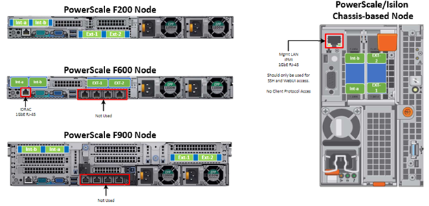
A PowerScale cluster’s back-end network is analogous to a distributed systems bus. Each node has two back-end interfaces for redundancy that run in an active/passive configuration (int-1 and int-2 above). The primary interface is connected to the primary switch; the secondary interface is connected to a separate switch.
For nodes using 40/100 Gb or 25/10 Gb Ethernet or InfiniBand connected with multimode fiber, the maximum cable length is 150 meters. This allows a cluster to span multiple rack rows, floors, and even buildings, if necessary. While this can solve floor space challenges, in order to perform any physical administration activity on nodes, you must know where the equipment is located.
The following table shows the various PowerScale node types and their respective back-end network support. While Ethernet is the preferred medium – particularly for large PowerScale clusters – InfiniBand is also supported for compatibility with legacy Isilon clusters.
Node Models | Details |
F200, F600, F900 | F200: nodes support a 10 GbE or 25 GbE connection to the access switch using the same NIC. A breakout cable can connect up to four nodes to a single switch port.
F600: nodes support a 40 GbE or 100 GbE connection to the access switch using the same NIC.
F900: nodes support a 40 GbE or 100 GbE connection to the access switch using the same NIC. |
H700, H7000, A300, A3000 | Supports 40 GbE or 100 GbE connection to the access switch using the same NIC.
OR
Supports 25 GbE or 10 GbE connection to the leaf using the same NIC. A breakout cable can connect a 40 GbE switch port to four 10 GbE nodes or a 100 GbE switch port to four 25 GbE nodes. |
F810, F800, H600, H500, H5600 | Performance nodes support a 40 GbE connection to the access switch. |
A200, A2000, H400 | Archive nodes support a 10GbE connection to the access switch using a breakout cable. A breakout cable can connect a 40 GbE switch port to four 10 GbE nodes or a 100 GbE switch port to four 10 GbE nodes. |
Currently only Dell Technologies approved switches are supported for back-end Ethernet and IB cluster interconnection. These include:
Switch | Port | Port | Height | Role | Notes |
Dell S4112 | 24 | 10GbE | ½ | ToR | 10 GbE only. |
Dell 4148 | 48 | 10GbE | 1 | ToR | 10 GbE only. |
Dell S5232 | 32 | 100GbE | 1 | Leaf or Spine | Supports 4x10GbE or 4x25GbE breakout cables.
Total of 124 10GbE or 25GbE nodes as top-of-rack back-end switch.
Port 32 does not support breakout. |
Dell Z9100 | 32 | 100GbE | 1 | Leaf or Spine | Supports 4x10GbE or 4x25GbE breakout cables.
Total of 128 10GbE or 25GbE nodes as top-of-rack back-end switch. |
Dell Z9264 | 64 | 100GbE | 2 | Leaf or Spine | Supports 4x10GbE or 4x25GbE breakout cables.
Total of 128 10GbE or 25GbE nodes as top-of-rack back-end switch. |
Arista 7304 | 128 | 40GbE | 8 | Enterprise core | 40GbE or 10GbE line cards. |
Arista 7308 | 256 | 40GbE | 13 | Enterprise/ large cluster | 40GbE or 10GbE line cards. |
Mellanox Neptune MSX6790 | 36 | QDR | 1 | IB fabric | 32Gb/s quad data rate InfiniBand. |
Be aware that the use of patch panels is not supported for PowerScale cluster back-end connections, regardless of overall cable lengths. All connections must be a single link, single cable directly between the node and back-end switch. Also, Ethernet and InfiniBand switches must not be reconfigured or used for any traffic beyond a single cluster.
Support for leaf spine back-end Ethernet network topologies was first introduced in OneFS 8.2. In a leaf-spine network switch architecture, the PowerScale nodes connect to leaf switches at the access, or leaf, layer of the network. At the next level, the aggregation and core network layers are condensed into a single spine layer. Each leaf switch connects to each spine switch to ensure that all leaf switches are no more than one hop away from one another. For example:
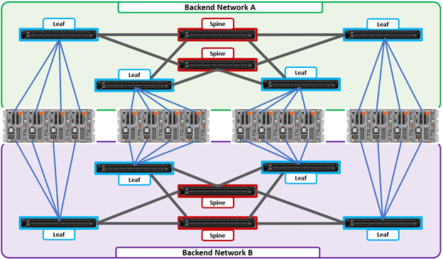
Leaf-to-spine switch connections require even distribution, to ensure the same number of spine connections from each leaf switch. This helps minimize latency and reduces the likelihood of bottlenecks in the back-end network. By design, a leaf spine network architecture is both highly scalable and redundant.
Leaf spine network deployments can have a minimum of two leaf switches and one spine switch. For small to medium clusters in a single rack, the back-end network typically uses two redundant top-of-rack (ToR) switches, rather than implementing a more complex leaf-spine topology.
Author: Nick Trimbee
Related Blog Posts

OneFS SmartQoS Configuration and Setup
Tue, 14 Mar 2023 16:06:06 -0000
|Read Time: 0 minutes
In the previous article in this series, we looked at the underlying architecture and management of SmartQoS in OneFS 9.5. Next, we’ll step through an example SmartQoS configuration using the CLI and WebUI.
After an initial set up, configuring a SmartQoS protocol Ops limit comprises four fundamental steps. These are:

Step | Task | Description | Example |
1 | Identify Metrics of interest | Used for tracking, to enforce an Ops limit | Uses ‘path’ and ‘protocol’ for the metrics to identify the workload. |
2 | Create a Dataset | For tracking all of the chosen metric categories | Create the dataset ‘ds1’ with the metrics identified. |
3 | Pin a Workload | To specify exactly which values to track within the chosen metrics | path: /ifs/data/client_exports protocol: nfs3 |
4 | Set a Limit | To limit Ops based on the dataset, metrics (categories), and metric values defined by the workload | Protocol_ops limit: 100 |
Step 1:

First, select a metric of interest. For this example, we’ll use the following:
- Protocol: NFSv3
- Path: /ifs/test/expt_nfs
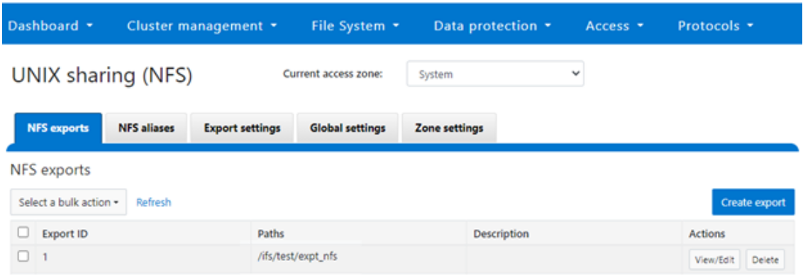
If not already present, create and verify an NFS export – in this case at /ifs/test/expt_nfs:
# isi nfs exports create /ifs/test/expt_nfs
# isi nfs exports list
ID Zone Paths Description
------------------------------------------------
1 System /ifs/test/expt_nfs
------------------------------------------------
Or from the WebUI, under Protocols UNIX sharing (NFS) > NFS exports:
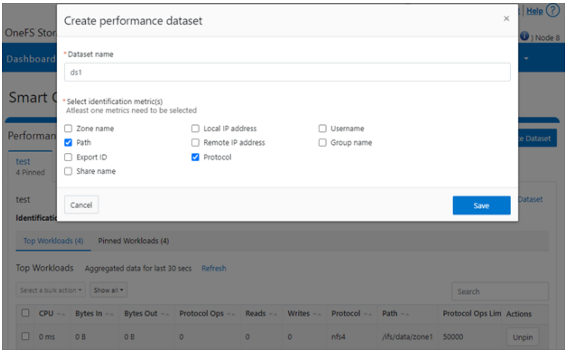
Step 2:

The ‘dataset’ designation is used to categorize workload by various identification metrics, including:
ID Metric | Details |
Username | UID or SID |
Primary groupname | Primary GID or GSID |
Secondary groupname | Secondary GID or GSID |
Zone name |
|
IP address | Local or remote IP address or IP address range |
Path | Except for S3 protocol |
Share | SMB share or NFS export ID |
Protocol | NFSv3, NFSv4, NFSoRDMA, SMB, or S3 |
SmartQoS in OneFS 9.5 only allows protocol Ops as the transient resources used for configuring a limit ceiling.
For example, you can use the following CLI command to create a dataset ‘ds1’, specifying protocol and path as the ID metrics:
# isi performance datasets create --name ds1 protocol path
Created new performance dataset 'ds1' with ID number 1.
Note: Resource usage tracking by the ‘path’ metric is only supported by SMB and NFS.
The following command displays any configured datasets:
# isi performance datasets list
Or, from the WebUI, by navigating to Cluster management > Smart QoS:
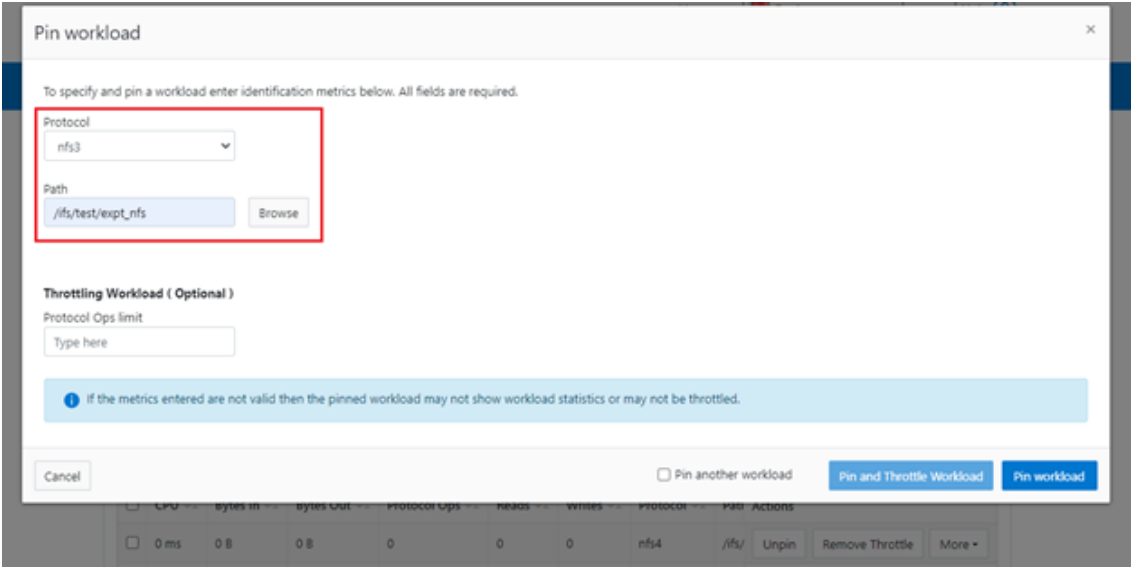
Step 3:

After you have created the dataset, you can pin a workload to it by specifying the metric values. For example:
# isi performance workloads pin ds1 protocol:nfs3 path: /ifs/test/expt_nfs
Pinned performance dataset workload with ID number 100.
Or from the WebUI, by browsing to Cluster management > Smart QoS > Pin workload:
After pinning a workload, the entry appears in the ‘Top Workloads’ section of the WebUI page. However, wait at least 30 seconds to start receiving updates.
To list all the pinned workloads from a specified dataset, use the following command:
# isi performance workloads list ds1
The prior command’s output indicates that there are currently no limits set for this workload.
By default, a protocol ops limit exists for each workload. However, it is set to the maximum (the maximum value of a 64-bit unsigned integer). This is represented in the CLI output by a dash (“-“) if a limit has not been explicitly configured:
# isi performance workloads list ds1
ID   Name  Metric Values           Creation Time       Cluster Resource Impact  Client Impact   Limits
--------------------------------------------------------------------------------------
100  -     path:/ifs/test/expt_nfs 2023-02-02T12:06:05  -          -              -
           protocol:nfs3
--------------------------------------------------------------------------------------
Total: 1
Step 4:

For a pinned workload in a dataset, you can configure a limit for the protocol ops limit from the CLI, using the following syntax:
# isi performance workloads modify <dataset> <workload ID> --limits protocol_ops:<value>
When configuring SmartQoS, always be aware that it is a powerful performance throttling tool which can be applied to significant areas of a cluster’s data and userbase. For example, protocol Ops limits can be configured for metrics such as ‘path:/ifs’, which would affect the entire /ifs filesystem, or ‘zone_name:System’ which would limit the System access zone and all users within it. While such configurations are entirely valid, they would have a significant, system-wide impact. As such, exercise caution when configuring SmartQoS to avoid any inadvertent, unintended, or unexpected performance constraints.
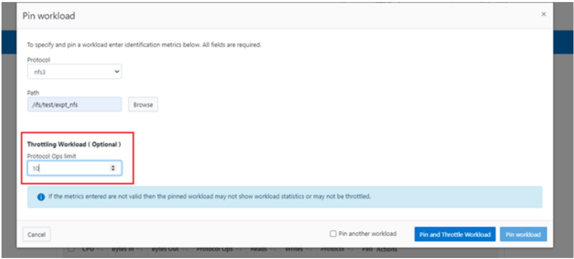
In the following example, the dataset is ‘ds1’, the workload ID is ‘100’, and the protocol Ops limit is set to the value ‘10’:
# isi performance workloads modify ds1 100 --limits protocol_ops:10
protocol_ops: 18446744073709551615 -> 10
Or from the WebUI, by browsing to Cluster management > Smart QoS > Pin and throttle workload:
You can use the ‘isi performance workloads’ command in ‘list’ mode to show details of the workload ‘ds1’. In this case, ‘Limits’ is set to protocol_ops = 10.
# isi performance workloads list test
ID   Name  Metric Values           Creation Time       Cluster Resource Impact  Client Impact   Limits
--------------------------------------------------------------------------------------
100  -     path:/ifs/test/expt_nfs 2023-02-02T12:06:05  -   -  protocol_ops:10
           protocol:nfs3
--------------------------------------------------------------------------------------
Total: 1
Or in ‘view’ mode:
# isi performance workloads view ds1 100
                     ID: 100
                   Name: -
          Metric Values: path:/ifs/test/expt_nfs, protocol:nfs3
          Creation Time: 2023-02-02T12:06:05
Cluster Resource Impact: -
          Client Impact: -
                 Limits: protocol_ops:10
Or from the WebUI, by browsing to Cluster management > Smart QoS:

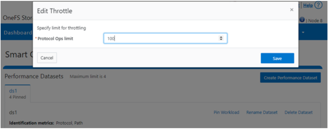
You can easily modify the limit value of a pinned workload with the following CLI syntax. For example, to set the limit to 100 Ops:
# isi performance workloads modify ds1 100 --limits protocol_ops:100
Or from the WebUI, by browsing to Cluster management > Smart QoS > Edit throttle:
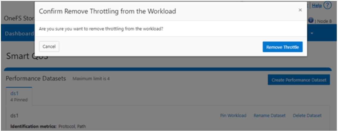
Similarly, you can use the following CLI command to easily remove a protocol ops limit for a pinned workload:
# isi performance workloads modify ds1 100 --no-protocol-ops-limit
Or from the WebUI, by browsing to Cluster management > Smart QoS > Remove throttle:
Author: Nick Trimbee

OneFS Hardware Network Considerations
Wed, 07 Dec 2022 20:54:43 -0000
|Read Time: 0 minutes
As we’ve seen in prior articles in this series, OneFS and the PowerScale platforms support a variety of Ethernet speeds, cable and connector styles, and network interface counts, depending on the node type selected. However, unlike the back-end network, Dell Technologies does not specify particular front-end switch models, allowing PowerScale clusters to seamlessly integrate into the data link layer (layer 2) of an organization’s existing Ethernet IP network infrastructure. For example:
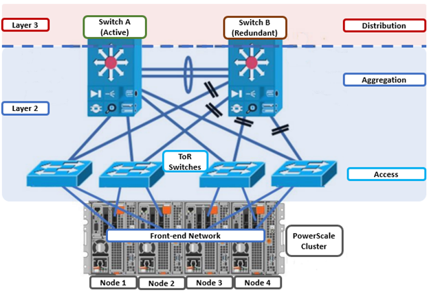
A layer 2 looped topology, as shown here, extends VLANs between the distribution/aggregation switches, with spanning tree protocol (STP) preventing network loops by shutting down redundant paths. The access layer uplinks can be used to load balance VLANs. This distributed architecture allows the cluster’s external network to connect to multiple access switches, affording each node similar levels of availability, performance, and management properties.
Link aggregation can be used to combine multiple Ethernet interfaces into a single link-layer interface, and is implemented between a single switch and a PowerScale node, where transparent failover or switch port redundancy is required. Link aggregation assumes that all links are full duplex, point to point, and at the same data rate, providing graceful recovery from link failures. If a link fails, traffic is automatically sent to the next available link without disruption.
Quality of service (QoS) can be implemented through differentiated services code point (DSCP), by specifying a value in the packet header that maps to an ‘effort level’ for traffic. Because OneFS does not provide an option for tagging packets with a specified DSCP marking, the recommended practice is to configure the first hop ports to insert DSCP values on the access switches connected to the PowerScale nodes. OneFS does however retain headers for packets that already have a specified DSCP value.
When designing a cluster, the recommendation is that each node have at least one front-end interface configured, preferably in at least one static SmartConnect zone. Although a cluster can be run in a ‘not all nodes on the network’ (NANON) configuration, where feasible, the recommendation is to connect all nodes to the front-end network(s). Additionally, cluster services such as SNMP, ESRS, ICAP, and auth providers (AD, LDAP, NIS, and so on) prefer that each node have an address that can reach the external servers.
In contrast with scale-up NAS platforms that use separate network interfaces for out-of-band management and configuration, OneFS traditionally performs all cluster network management in-band. However, PowerScale nodes typically contain a dedicated 1Gb Ethernet port that can be configured for use as a management network by ICMP or iDRAC, simplifying administration of a large cluster. OneFS also supports using a node’s serial port as an RS-232 out-of-band management interface. This practice is highly recommended for large clusters. Serial connectivity can provide reliable BIOS-level command line access for on-site or remote service staff to perform maintenance, troubleshooting, and installation operations.
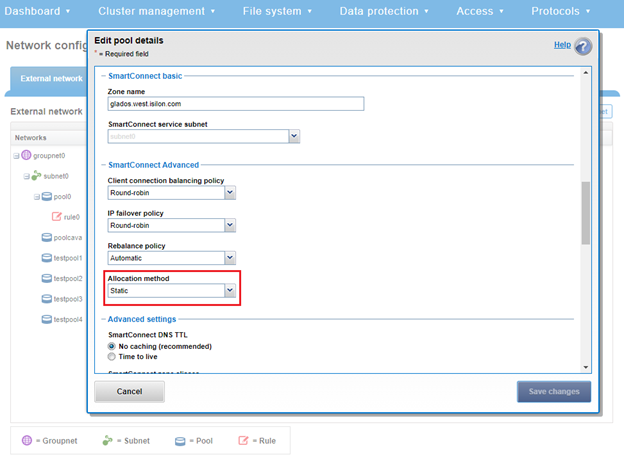
SmartConnect provides a configurable allocation method for each IP address pool:
Allocation Method | Attributes |
Static | • One IP per interface is assigned, will likely require fewer IPs to meet minimum requirements • No Failover of IPs to other interfaces |
Dynamic | • Multiple IPs per interface is assigned, will require more IPs to meet minimum requirements • Failover of IPs to other interfaces, failback policies are needed |
The default ‘static’ allocation assigns a single persistent IP address to each interface selected in the pool, leaving additional pool IP addresses unassigned if the number of addresses exceeds the total interfaces.
The lowest IP address of the pool is assigned to the lowest Logical Node Number (LNN) from the selected interfaces. The same is true for the second-lowest IP address and LNN, and so on. If a node or interface becomes unavailable, this IP address does not move to another node or interface. Also, when the node or interface becomes unavailable, it is removed from the SmartConnect zone, and new connections will not be assigned to the node. When the node is available again, SmartConnect automatically adds it back into the zone and assigns new connections.
By contrast, ‘dynamic’ allocation divides all available IP addresses in the pool across all selected interfaces. OneFS attempts to assign the IP addresses as evenly as possible. However, if the interface-to-IP address ratio is not an integer value, a single interface might have more IP addresses than another. As such, wherever possible, ensure that all the interfaces have the same number of IP addresses.
In concert with dynamic allocation, dynamic failover provides high availability by transparently migrating IP addresses to another node when an interface is not available. If a node becomes unavailable, all the IP addresses it was hosting are reallocated across the new set of available nodes in accordance with the configured failover load-balancing policy. The default IP address failover policy is round robin, which evenly distributes IP addresses from the unavailable node across available nodes. Because the IP address remains consistent, irrespective of the node on which it resides, failover to the client is transparent, so high availability is seamless.
The other available IP address failover policies are the same as the initial client connection balancing policies, that is, connection count, throughput, or CPU usage. In most scenarios, round robin is not only the best option but also the most common. However, the other failover policies are available for specific workflows.
The decision on whether to implement dynamic failover depends on the protocol(s) being used, general workflow attributes, and any high-availability design requirements:
Protocol | State | Suggested Allocation Strategy |
NFSv3 | Stateless | Dynamic |
NFSv4 | Stateful | Dynamic or Static, depending on mount daemon, OneFS version, and Kerberos. |
SMB | Stateful | Dynamic or Static |
SMB Multi-channel | Stateful | Dynamic or Static |
S3 | Stateless | Dynamic or Static |
HDFS | Stateful | Dynamic or Static. HDFS uses separate name-node and data-node connections. Allocation strategy depends on the need for data locality and/or multi-protocol, that is:
HDFS + NFSv3 : Dynamic Pool
HDFS + SMB : Static Pool |
HTTP | Stateless | Static |
FTP | Stateful | Static |
SyncIQ | Stateful | Static required |
Assigning each workload or data store to a unique IP address enables OneFS SmartConnect to move each workload to one of the other interfaces. This minimizes the additional work that a remaining node in the SmartConnect pool must absorb and ensures that the workload is evenly distributed across all the other nodes in the pool.
Static IP pools require one IP address for each logical interface within the pool. Because each node provides two interfaces for external networking, if link aggregation is not configured, this would require 2*N IP addresses for a static pool.
Determining the number of IP addresses within a dynamic allocation pool varies depending on the workflow, node count, and the estimated number of clients that would be in a failover event. While dynamic pools need, at a minimum, the number of IP addresses to match a pool’s node count, the ‘N * (N – 1)’ formula can often prove useful for calculating the required number of IP addresses for smaller pools. In this equation, N is the number of nodes that will participate in the pool.
For example, a SmartConnect pool with four-node interfaces, using the ‘N * (N – 1)’ model will result in three unique IP addresses being allocated to each node. A failure on one node interface will cause each of that interface’s three IP addresses to fail over to a different node in the pool. This ensures that each of the three active interfaces remaining in the pool receives one IP address from the failed node interface. If client connections to that node are evenly balanced across its three IP addresses, SmartConnect will evenly distribute the workloads to the remaining pool members. For larger clusters, this formula may not be feasible due to the sheer number of IP addresses required.
Enabling jumbo frames (Maximum Transmission Unit set to 9000 bytes) typically yields improved throughput performance with slightly reduced CPU usage than when using standard frames, where the MTU is set to 1500 bytes. For example, with 40 Gb Ethernet connections, jumbo frames provide about five percent better throughput and about one percent less CPU usage.
OneFS provides the ability to optimize storage performance by designating zones to support specific workloads or subsets of clients. Different network traffic types can be segregated on separate subnets using SmartConnect pools.
For large clusters, partitioning the cluster’s networking resources and allocating bandwidth to each workload can help minimize the likelihood that heavy traffic from one workload will affect network throughput for another. This is particularly true for SyncIQ replication and NDMP backup traffic, which can frequently benefit from its own set of interfaces, separate from user and client IO load.
The ‘groupnet’ networking object is part of OneFS’ support for multi-tenancy. Groupnets sit above subnets and pools and allow separate Access Zones to contain distinct DNS settings.
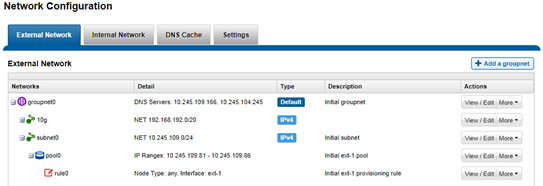
The management and data network(s) can then be incorporated into different Access Zones, each with their own DNS, directory access services, and routing, as appropriate.
Author: Nick Trimbee