


OneFS Hardware Installation Considerations

When it comes to physically installing PowerScale nodes, most use a 35 inch depth chassis and will fit in a standard depth data center cabinet. Nodes can be secured to standard storage racks with their sliding rail kits, included in all node packaging and compatible with racks using either 3/8 inch square holes, 9/32 inch round holes, or 10-32 / 12-24 / M5X.8 / M6X1 pre-threaded holes. These supplied rail kit mounting brackets are adjustable in length, from 24 inches to 36 inches, to accommodate different rack depths. When selecting an enclosure for PowerScale nodes, ensure that the rack supports the minimum and maximum rail kit sizes.
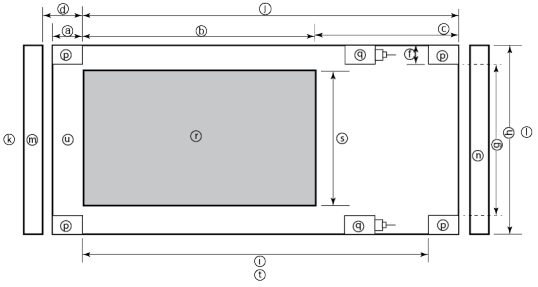
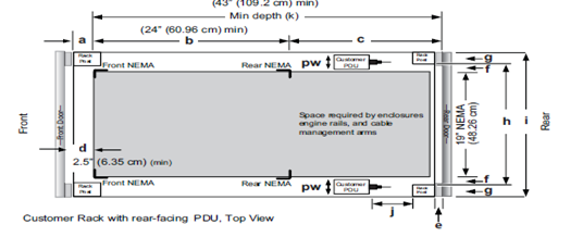
Rack Component | Description |
a | Distance between front surface of the rack and the front NEMA rail |
b | Distance between NEMA rails, minimum=24in (609.6mm), max=34in (863.6mm) |
c | Distance between the rear of the chassis to the rear of the rack, min=2.3in (58.42mm) |
d | Distance between inner front of the front door and the NEMA rail, min=2.5in (63.5mm) |
e | Distance between the inside of the rear post and the rear vertical edge of the chassis and rails, min=2.5in (63.5mm) |
f | Width of the rear rack post |
g | 19in (486.2mm)+(2e), min=24in (609.6mm) |
h | 19in (486.2mm) NEMA+(2e)+(2f) Note: Width of the PDU+0.5in (13mm) <=e +f
If j=i+c+PDU depth+3in (76.2mm), then h=min 23.6in (600mm)
Assuming the PDU is mounted beyond i+c. |
i | Chassis depth: Normal chassis=35.80in (909mm) : Deep chassis=40.40in (1026mm) Switch depth (measured from the front NEMA rail): Note: The inner rail is fixed at 36.25in (921mm)
Allow up to 6in (155mm) for cable bend radius when routing up to 32 cables to one side of the rack. Select the greater of the installed equipment. |
j | Minimum rack depth=i+c |
k | Front |
l | Rear |
m | Front door |
n | Rear door |
p | Rack post |
q | PDU |
r | NEMA |
s | NEMA 19 inch |
t | Rack top view |
u | Distance from front NEMA to chassis face: Dell PowerScale deep and normal chassis = 0in |
However, the high-capacity models, such as the F800/810, H7000, H5600, A3000 and A2000, have 40 inch depth chassis and require extended depth cabinets, such as the APC 3350 or Dell Titan-HD rack.
Additional room must be provided for opening the FRU service trays at the rear of the nodes and, in the chassis-based 4RU platforms, the disk sleds at the front of the chassis. Except for the 2RU F900, the stand-alone PowerScale all-flash nodes are 1RU in height (including the 1RU diskless P100 accelerator and B100 backup accelerator nodes).
Power-wise, each cabinet typically requires between two and six independent single or three-phase power sources. To determine the specific requirements, use the published technical specifications and device rating labels for the devices to calculate the total current draw for each rack.
Specification | North American 3 wire connection (2 L and 1 G) | International 3 wire connection (1 L, 1 N, and 1 G) |
Input nominal voltage | 200–240 V ac +/- 10% L – L nom | 220–240 V ac +/- 10% L – L nom |
Frequency | 50–60 Hz | 50–60 Hz |
Circuit breakers | 30 A | 32 A |
Power zones | Two | Two |
Power requirements at site (minimum to maximum) | Single-phase: six 30A drops, two per zone
Three-phase Delta: two 50A drops, one per zone
Three-phase Wye: two 32A drops, one per zone | Single-phase: six 30A drops, two per zone
Three-phase Delta: two 50A drops, one per zone
Three-phase Wye: two 32A drops, one per zone |
Additionally, the recommended environmental conditions to support optimal PowerScale cluster operation are as follows:
Attribute | Details |
Temperature | Operate at >=90 percent of the time between 10 degrees Celsius to 35 degrees Celsius, and <=10 percent of the time between 5 degrees Celsius to 40 degrees Celsius. |
Humidity | 40 to 55 percent relative humidity |
Weight | A fully configured cabinet must sit on at least two floor tiles, and can weigh approximately 1588 kilograms (3500 pounds). |
Altitude | 0 meters to 2439 meters (0 to 8,000 ft) above sea level operating altitude. |
Weight is a critical factor to keep in mind, particularly with the chassis-based nodes. Individual 4RU chassis can weigh up to around 300 lbs each, and the maximum floor tile capacity for each individual cabinet or rack must be kept in mind. For the deep node styles (H7000, H5600, A3000 and A2000), the considerable node weight may prevent racks from being fully populated with PowerScale equipment. If the cluster uses a variety of node types, installing the larger, heavier nodes at the bottom of each rack and the lighter chassis at the top can help distribute weight evenly across the cluster racks’ floor tiles.
Note that there are no lift handles on the PowerScale 4RU chassis. However, the drive sleds can be removed to provide handling points if no lift is available. With all the drive sleds removed, but leaving the rear compute modules inserted, the chassis weight drops to a more manageable 115 lbs or so. It is strongly recommended to use a lift for installation of 4RU chassis.
Cluster back-end switches ship with the appropriate rails (or tray) for proper installation of the switch in the rack. These rail kits are adjustable to fit NEMA front rail to rear rail spacing ranging from 22 in to 34 in.
Note that some manufacturers’ Ethernet switch rails are designed to overhang the rear NEMA rails, helping to align the switch with the PowerScale chassis at the rear of the rack. These require a minimum clearance of 36 in from the front NEMA rail to the rear of the rack, in order to ensure that the rack door can be closed.
Consider the following large cluster topology, for example:
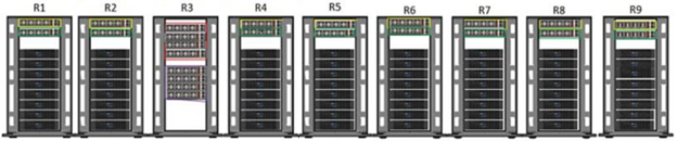
This contiguous rack architecture is designed to scale up to the current maximum PowerScale cluster size of 252 nodes, in 63 4RU chassis, across nine racks as the environment grows – while still keeping cable management relatively simple. Note that this configuration assumes 1RU per node. If you are using F900 nodes, which are 2RU in size, be sure to budget for additional rack capacity.
Successful large cluster infrastructures depend on the proficiency of the installer and their optimizations for maintenance and future expansion. Some good data center design practices include:
- Pre-allocating and reserving adjacent racks in the same isle to accommodate the anticipated future cluster expansion
- Reserving an empty ‘mailbox’ slot in the top half of each rack for any pass-through cable management needs
- Dedicating one of the racks in the group for the back-end and front-end distribution/spine switches – in this case rack R3
For Hadoop workloads, PowerScale clusters are compatible with the rack awareness feature of HDFS to provide balancing in the placement of data. Rack locality keeps the data flow internal to the rack.
Excess cabling can be neatly stored in 12” service coils on a cable tray above the rack, if available, or at the side of the rack as illustrated below.
The use of intelligent power distribution units (PDUs) within each rack can facilitate the remote power cycling of nodes, if desired.
For deep nodes such as the H7000 and A3000 hardware, where chassis depth can be a limiting factor, horizontally mounted PDUs within the rack can be used in place of vertical PDUs, if necessary. If front-mounted, partial depth Ethernet switches are deployed, you can install horizontal PDUs in the rear of the rack directly behind the switches to maximize available rack capacity.
With copper cables (such as SFP+, QSFP, CX4), the maximum cable length is typically limited to 10 meters or less. After factoring in for dressing the cables to maintain some level of organization and proximity within the racks and cable trays, all the racks with PowerScale nodes need to be near each other – either in the same rack row or close by in an adjacent row – or adopt a leaf-spine topology, with leaf switches in each rack.
If greater physical distance between nodes is required, support for multimode fiber (QSFP+, MPO, LC, etc) extends the cable length limitation to 150 meters. This allows nodes to be housed on separate floors or on the far side of a floor in a datacenter if necessary. While solving the floor space problem, this does have the potential to introduce new administrative and management challenges.
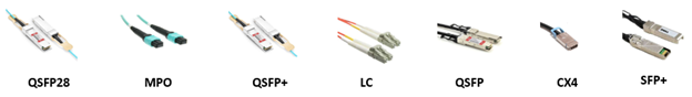
The following table lists the various cable types, form factors, and supported lengths available for PowerScale nodes:
Cable Form Factor | Medium | Speed (Gb/s) | Max Length |
QSFP28 | Optical | 100Gb | 30M |
MPO | Optical | 100/40Gb | 150M |
QSFP28 | Copper | 100Gb | 5M |
QSFP+ | Optical | 40Gb | 10M |
LC | Optical | 25/10Gb | 150M |
QSFP+ | Copper | 40Gb | 5M |
SFP28 | Copper | 25Gb | 5M |
SFP+ | Copper | 10Gb | 7M |
CX4 | Copper | IB QDR/DDR | 10M |
The connector types for the cables above can be identified as follows:
As for the nodes themselves, the following rear views indicate the locations of the various network interfaces:
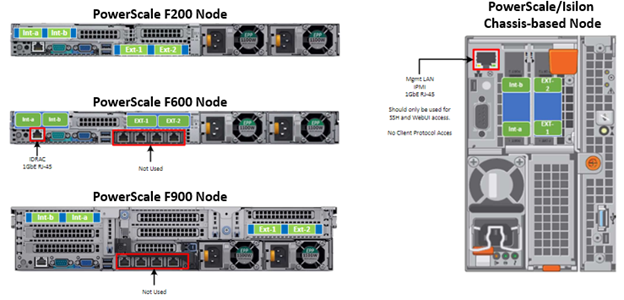
Note that Int-a and int-b indicate the primary and secondary back-end networks, whereas Ext-1 and Ext-2 are the front-end client networks interfaces.
Be aware that damage to the InfiniBand or Ethernet cables (copper or optical fiber) can negatively affect cluster performance. Never bend cables beyond the recommended bend radius, which is typically 10–12 times the diameter of the cable. For example, if a cable is 1.6 inches, round up to 2 inches and multiply by 10 for an acceptable bend radius.
Cables differ, so follow the explicit recommendations of the cable manufacturer.
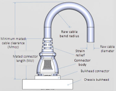
The most important design attribute for bend radius consideration is the minimum mated cable clearance (Mmcc). Mmcc is the distance from the bulkhead of the chassis through the mated connectors/strain relief including the depth of the associated 90 degree bend. Multimode fiber has many modes of light (fiber optic) traveling through the core. As each of these modes moves closer to the edge of the core, light and the signal are more likely to be reduced, especially if the cable is bent. In a traditional multimode cable, as the bend radius is decreased, the amount of light that leaks out of the core increases, and the signal decreases. Best practices for data cabling include:
- Keep cables away from sharp edges or metal corners.
- Avoid bundling network cables with power cables. If network and power cables are not bundled separately, electromagnetic interference (EMI) can affect the data stream.
- When bundling cables, do not pinch or constrict the cables.
- Avoid using zip ties to bundle cables. Instead use Velcro hook-and-loop ties that do not have hard edges, and can be removed without cutting. Fastening cables with Velcro ties also reduces the impact of gravity on the bend radius.
Note that the effects of gravity can also decrease the bend radius and result in degradation of signal power and quality.
Cables, particularly when bundled, can also obstruct the movement of conditioned air around the cluster, and cables should be secured away from fans. Flooring seals and grommets can be useful to keep conditioned air from escaping through cable holes. Also ensure that smaller Ethernet switches are drawing cool air from the front of the rack, not from inside the cabinet. This can be achieved either with switch placement or by using rack shelving.
Author: Nick Trimbee
Related Blog Posts

OneFS Hardware Environmental and Logistical Considerations
Wed, 07 Dec 2022 17:28:21 -0000
|Read Time: 0 minutes
In this article, we turn our attention to some of the environmental and logistical aspects of cluster design, installation, and management.
In addition to available rack space and physical proximity of nodes, provision needs to be made for adequate power and cooling as the cluster expands. New generations of drives and nodes typically deliver increased storage density, which often magnifies the power draw and cooling requirements per rack unit.
The recommendation is for a large cluster’s power supply to be fully redundant and backed up with a battery UPS and/or power generator. In the worst instance, if a cluster does loose power, the nodes are protected internally by filesystem journals which preserve any in-flight uncommitted writes. However, the time to restore power and bring up a large cluster from an unclean shutdown can be considerable.
Like most data center equipment, the cooling fans in PowerScale nodes and switches pull air from the front to back of the chassis. To complement this, data centers often employ a hot isle/cold isle rack configuration, where cool, low humidity air is supplied in the aisle at the front of each rack or cabinet either at the floor or ceiling level, and warm exhaust air is returned at ceiling level in the aisle to the rear of each rack.
Given the significant power draw, heat density, and weight of cluster hardware, some datacenters are limited in the number of nodes each rack can support. For partially filled racks, the use of blank panels to cover the front and rear of any unfilled rack units can help to efficiently direct airflow through the equipment.
The table below shows the various front and back-end network speeds and connector form factors across the PowerScale storage node portfolio.
Speed (Gb/s) | Form Factor | Front-end/ | Speed (Gb/s) |
100/40 | QSFP28 | Back-end | F900, F600, H700, H7000, A300, A3000, P100, B100 |
40 QDR | QSFP+ | Back-end | F800, F810, H600, H5600, H500, H400, A200, A2000 |
25/10 | SFP28 | Back-end | F900, F600, F200, H700, H7000, A300, A3000, P100, B100 |
10 QDR | QSFP+ | Back-end | H400, A200, A2000 |
100/40 | QSFP28 | Front-end | F900, F600, H700, H7000, A300, A3000, P100, B100 |
40 QDR | QSFP+ | Front-end | F800, F810, H600, H5600, H500, H400, A200, A2000 |
25/10 | SFP28 | Front-end | F900, F600, F200, H700, H7000, A300, A3000, P100, B100 |
25/10 | SFP+ | Front-end | F800, F810, H600, H5600, H500, H400, A200, A2000 |
10 QDR | SFP+ | Front-end | F800, F810, H600, H5600, H500, H400, A200, A2000 |
With large clusters, especially when the nodes may not be racked in a contiguous manner, it is highly advised to have all the nodes and switches connected to serial console concentrators and remote power controllers. However, to perform any physical administration or break/fix activity on nodes, you must know where the equipment is located and have administrative resources available to access and service all locations.
As such, the following best practices are recommended:
- Develop and update thorough physical architectural documentation.
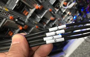
- Implement an intuitive cable coloring standard.
- Be fastidious and consistent about cable labeling.
- Use the appropriate length of cable for the run and create a neat 12” loop of any excess cable, secured with Velcro.
- Observe appropriate cable bend ratios, particularly with fiber cables.
- Dress cables and maintain a disciplined cable management ethos.
- Keep a detailed cluster hardware maintenance log.
- Where appropriate, maintain a ‘mailbox’ space for cable management.
Disciplined cable management and labeling for ease of identification is particularly important in larger PowerScale clusters, where density of cabling is high. Each chassis can require up to 28 cables, as shown in the following table:
Cabling Component | Medium | Cable Quantity per Chassis |
Back-end network | Ethernet or Infiniband | 8 |
Front-end network | Ethernet | 8 |
Management interface | 1Gb Ethernet | 4 |
Serial console | DB9 RS 232 | 4 |
Power cord | 110V or 220V AC power | 4 |
Total |
| 28 |
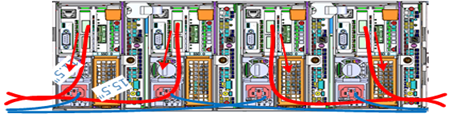
The recommendations for cabling a PowerScale chassis are:
- Split cabling in the middle of the chassis, between nodes 2 and 3.
- Route Ethernet and Infiniband cables towards the lower side of the chassis.
- Connect power cords for nodes 1 and 3 to PDU A, and power cords for nodes 2 and 4 to PDU B.
- Bundle network cables with the AC power cords for ease of management.
- Leave enough cable slack for servicing each individual node’s FRUs.
Similarly, the stand-alone F-series all flash nodes, in particular the 1RU F600 and F200 nodes, also have a similar density of cabling per rack unit:
Cabling Component | Medium | Cable Quantity per |
Back-end network | 10 or 40 Gb Ethernet or QDR Infiniband | 2 |
Front-end network | 10 or 40Gb Ethernet | 2 |
Management interface | 1Gb Ethernet | 1 |
Serial console | DB9 RS 232 | 1 |
Power cord | 110V or 220V AC power | 2 |
Total |
| 8 |
Consistent and meticulous cable labeling and management is particularly important in large clusters. PowerScale chassis that employ both front and back-end Ethernet networks can include up to 20 Ethernet connections per 4RU chassis.
In each node’s compute module, there are two PCI slots for the Ethernet cards (NICs). Viewed from the rear of the chassis, in each node the right hand slot (HBA Slot 0) houses the NIC for the front-end network, and the left hand slot (HBA Slot 1) houses the NIC for the front-end network. There is also a separate built-in 1Gb Ethernet port on each node for cluster management traffic.
While there is no requirement that node 1 aligns with port 1 on each of the back-end switches, it can certainly make cluster and switch management and troubleshooting considerably simpler. Even if exact port alignment is not possible, with large clusters, ensure that the cables are clearly labeled and connected to similar port regions on the back-end switches.
PowerScale nodes and the drives they contain have identifying LED lights to indicate when a component has failed and to allow proactive identification of resources. You can use the ‘isi led’ CLI command to illuminate specific node and drive indicator lights, as needed, to aid in identification.
Drive repair times depend on a variety of factors:
- OneFS release (determines Job Engine version and how efficiently it operates)
- System hardware (determines drive types, amount of CPU, RAM, and so on)
- Filesystem: Amount of data, data composition (lots of small vs large files), protection, tunables, and so on.
- Load on the cluster during the drive failure
A useful method to estimate future FlexProtect runtime is to use old repair runtimes as a guide, if available.
The drives in the PowerScale chassis-based platforms have a bay-grid nomenclature, where A-E indicates each of the sleds and 0-6 would point to the drive position in the sled. The drive closest to the front is 0, whereas the drive closest to the back is 2/3/5, depending on the drive sled type.
When it comes to updating and refreshing hardware in a large cluster, swapping nodes can be a lengthy process of somewhat unpredictable duration. Data has to be evacuated from each old node during the Smartfail process prior to its removal, and restriped and balanced across the new hardware’s drives. During this time there will also be potentially impactful group changes as new nodes are added and the old ones removed.
However, if replacing an entire node-pool as part of a tech refresh, a SmartPools filepool policy can be crafted to migrate the data to another nodepool across the back-end network. When complete, the nodes can then be Smartfailed out, which should progress swiftly because they are now empty.
If multiple nodes are Smartfailed simultaneously, at the final stage of the process the node remove is serialized with around 60 seconds pause between each. The Smartfail job places the selected nodes in read-only mode while it copies the protection stripes to the cluster’s free space. Using SmartPools to evacuate data from a node or set of nodes in preparation to remove them is generally a good idea, and is usually a relatively fast process.
Another efficient approach can often be to swap drives out into new chassis. In addition to being considerably faster, the drive swapping process focuses the disruption on a single whole cluster down event. Estimating the time to complete a drive swap, or ‘disk tango’ process, is simpler and more accurate and can typically be completed in a single maintenance window.
With PowerScale chassis-based platforms, such as the H700 and A300, the available hardware ‘tango’ options are expanded and simplified. Given the modular design of these platforms, the compute and chassis tango strategies typically replace the disk tango:
Replacement Strategy | Component | PowerScale F-series | Chassis-based Nodes | Description |
Disk tango | Drives / drive sleds | x | x | Swapping out data drives or drive sleds |
Compute tango | Chassis Compute modules |
| x | Rather than swapping out the twenty drive sleds in a chassis, it’s usually cleaner to exchange the four compute modules |
Chassis tango | 4RU Chassis |
| x | Typically only required if there’s an issue with the chassis mid-plane. |
Note that any of the above ‘tango’ procedures should only be executed under the recommendation and supervision of Dell support.
Author: Nick Trimbee

OneFS SmartQoS Configuration and Setup
Tue, 14 Mar 2023 16:06:06 -0000
|Read Time: 0 minutes
In the previous article in this series, we looked at the underlying architecture and management of SmartQoS in OneFS 9.5. Next, we’ll step through an example SmartQoS configuration using the CLI and WebUI.
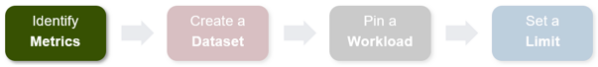
After an initial set up, configuring a SmartQoS protocol Ops limit comprises four fundamental steps. These are:

Step | Task | Description | Example |
1 | Identify Metrics of interest | Used for tracking, to enforce an Ops limit | Uses ‘path’ and ‘protocol’ for the metrics to identify the workload. |
2 | Create a Dataset | For tracking all of the chosen metric categories | Create the dataset ‘ds1’ with the metrics identified. |
3 | Pin a Workload | To specify exactly which values to track within the chosen metrics | path: /ifs/data/client_exports protocol: nfs3 |
4 | Set a Limit | To limit Ops based on the dataset, metrics (categories), and metric values defined by the workload | Protocol_ops limit: 100 |
Step 1:
First, select a metric of interest. For this example, we’ll use the following:
- Protocol: NFSv3
- Path: /ifs/test/expt_nfs
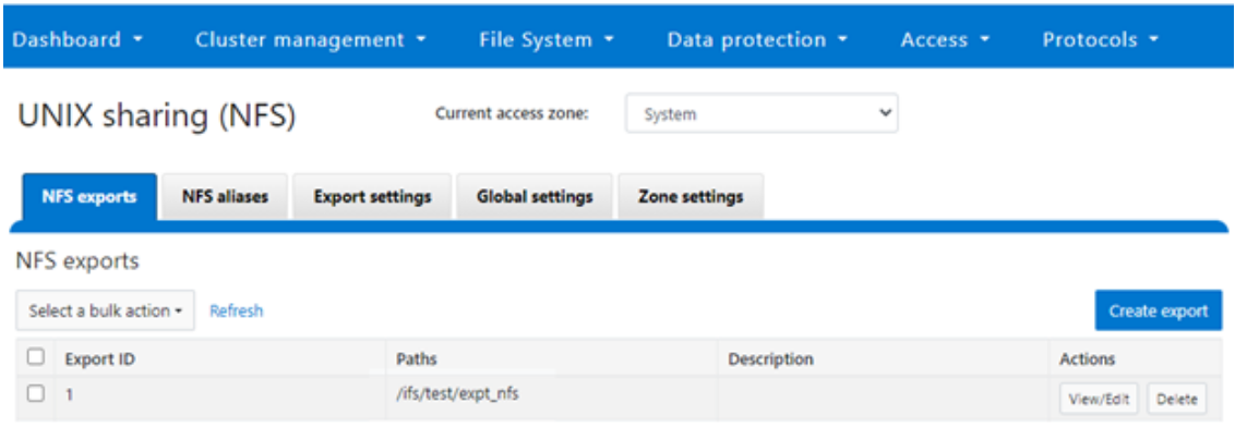
If not already present, create and verify an NFS export – in this case at /ifs/test/expt_nfs:
# isi nfs exports create /ifs/test/expt_nfs
# isi nfs exports list
ID Zone Paths Description
------------------------------------------------
1 System /ifs/test/expt_nfs
------------------------------------------------
Or from the WebUI, under Protocols UNIX sharing (NFS) > NFS exports:
Step 2:

The ‘dataset’ designation is used to categorize workload by various identification metrics, including:
ID Metric | Details |
Username | UID or SID |
Primary groupname | Primary GID or GSID |
Secondary groupname | Secondary GID or GSID |
Zone name |
|
IP address | Local or remote IP address or IP address range |
Path | Except for S3 protocol |
Share | SMB share or NFS export ID |
Protocol | NFSv3, NFSv4, NFSoRDMA, SMB, or S3 |
SmartQoS in OneFS 9.5 only allows protocol Ops as the transient resources used for configuring a limit ceiling.
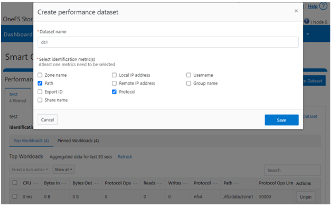
For example, you can use the following CLI command to create a dataset ‘ds1’, specifying protocol and path as the ID metrics:
# isi performance datasets create --name ds1 protocol path
Created new performance dataset 'ds1' with ID number 1.
Note: Resource usage tracking by the ‘path’ metric is only supported by SMB and NFS.
The following command displays any configured datasets:
# isi performance datasets list
Or, from the WebUI, by navigating to Cluster management > Smart QoS:
Step 3:
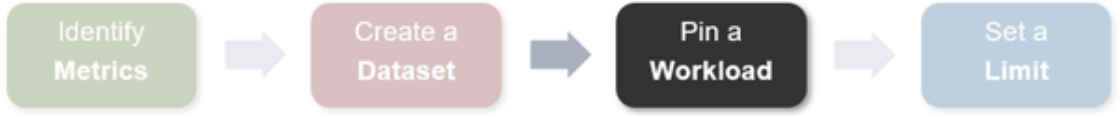
After you have created the dataset, you can pin a workload to it by specifying the metric values. For example:
# isi performance workloads pin ds1 protocol:nfs3 path: /ifs/test/expt_nfs
Pinned performance dataset workload with ID number 100.
Or from the WebUI, by browsing to Cluster management > Smart QoS > Pin workload:
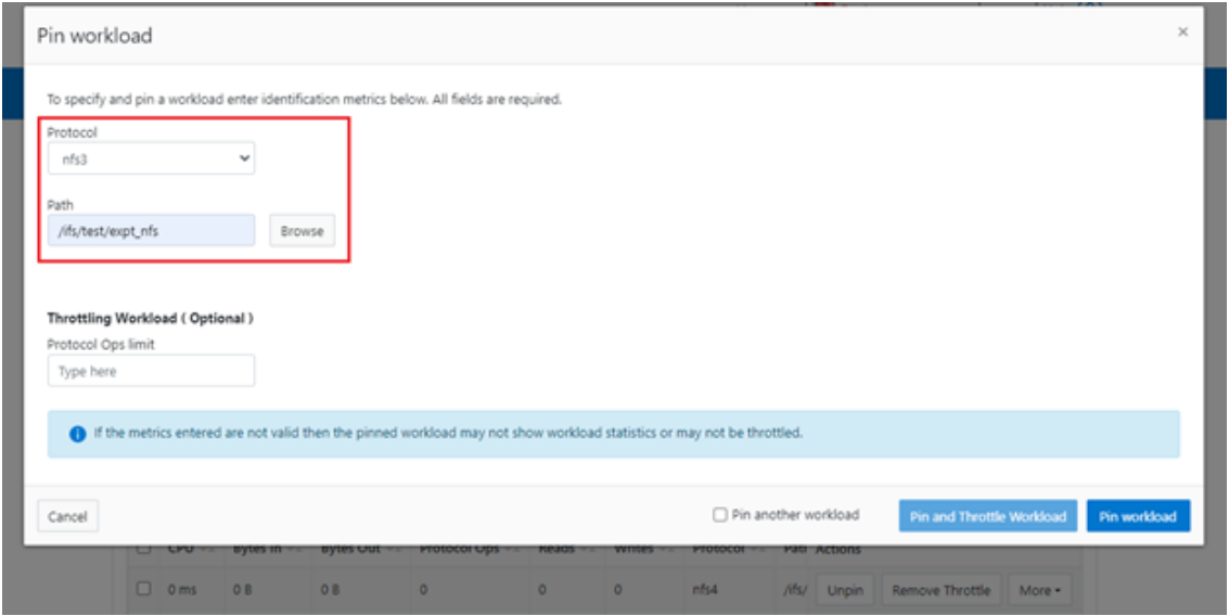
After pinning a workload, the entry appears in the ‘Top Workloads’ section of the WebUI page. However, wait at least 30 seconds to start receiving updates.
To list all the pinned workloads from a specified dataset, use the following command:
# isi performance workloads list ds1
The prior command’s output indicates that there are currently no limits set for this workload.
By default, a protocol ops limit exists for each workload. However, it is set to the maximum (the maximum value of a 64-bit unsigned integer). This is represented in the CLI output by a dash (“-“) if a limit has not been explicitly configured:
# isi performance workloads list ds1
ID   Name  Metric Values           Creation Time       Cluster Resource Impact  Client Impact   Limits
--------------------------------------------------------------------------------------
100  -     path:/ifs/test/expt_nfs 2023-02-02T12:06:05  -          -              -
           protocol:nfs3
--------------------------------------------------------------------------------------
Total: 1
Step 4:

For a pinned workload in a dataset, you can configure a limit for the protocol ops limit from the CLI, using the following syntax:
# isi performance workloads modify <dataset> <workload ID> --limits protocol_ops:<value>
When configuring SmartQoS, always be aware that it is a powerful performance throttling tool which can be applied to significant areas of a cluster’s data and userbase. For example, protocol Ops limits can be configured for metrics such as ‘path:/ifs’, which would affect the entire /ifs filesystem, or ‘zone_name:System’ which would limit the System access zone and all users within it. While such configurations are entirely valid, they would have a significant, system-wide impact. As such, exercise caution when configuring SmartQoS to avoid any inadvertent, unintended, or unexpected performance constraints.
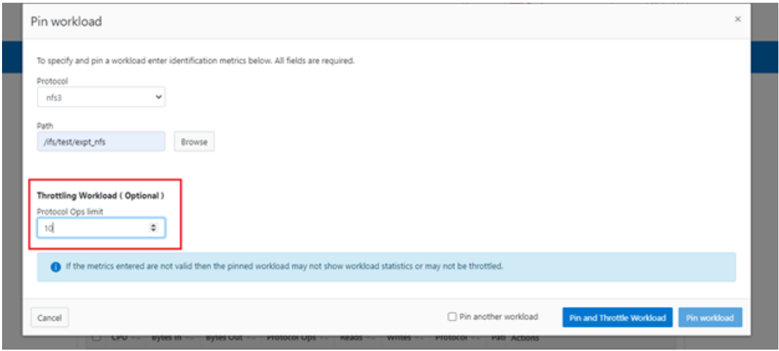
In the following example, the dataset is ‘ds1’, the workload ID is ‘100’, and the protocol Ops limit is set to the value ‘10’:
# isi performance workloads modify ds1 100 --limits protocol_ops:10
protocol_ops: 18446744073709551615 -> 10
Or from the WebUI, by browsing to Cluster management > Smart QoS > Pin and throttle workload:
You can use the ‘isi performance workloads’ command in ‘list’ mode to show details of the workload ‘ds1’. In this case, ‘Limits’ is set to protocol_ops = 10.
# isi performance workloads list test
ID   Name  Metric Values           Creation Time       Cluster Resource Impact  Client Impact   Limits
--------------------------------------------------------------------------------------
100  -     path:/ifs/test/expt_nfs 2023-02-02T12:06:05  -   -  protocol_ops:10
           protocol:nfs3
--------------------------------------------------------------------------------------
Total: 1
Or in ‘view’ mode:
# isi performance workloads view ds1 100
                     ID: 100
                   Name: -
          Metric Values: path:/ifs/test/expt_nfs, protocol:nfs3
          Creation Time: 2023-02-02T12:06:05
Cluster Resource Impact: -
          Client Impact: -
                 Limits: protocol_ops:10
Or from the WebUI, by browsing to Cluster management > Smart QoS:

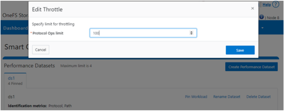
You can easily modify the limit value of a pinned workload with the following CLI syntax. For example, to set the limit to 100 Ops:
# isi performance workloads modify ds1 100 --limits protocol_ops:100
Or from the WebUI, by browsing to Cluster management > Smart QoS > Edit throttle:
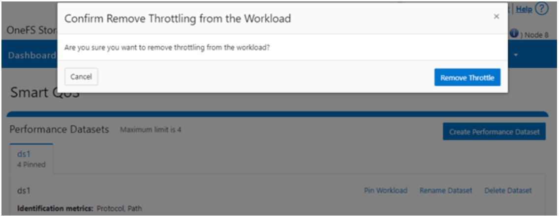
Similarly, you can use the following CLI command to easily remove a protocol ops limit for a pinned workload:
# isi performance workloads modify ds1 100 --no-protocol-ops-limit
Or from the WebUI, by browsing to Cluster management > Smart QoS > Remove throttle:
Author: Nick Trimbee