


OneFS Data Inlining – Performance and Monitoring

In the second of this series of articles on data inlining, we’ll shift the focus to monitoring and performance.
The storage efficiency potential of inode inlining can be significant for data sets comprising large numbers of small files, which would have required a separate inode and data blocks for housing these files prior to OneFS 9.3.
Latency-wise, the write performance for inlined file writes is typically comparable or slightly better as compared to regular files, because OneFS does not have to allocate extra blocks and protect them. This is also true for reads, because OneFS doesn’t have to search for and retrieve any blocks beyond the inode itself. This also frees up space in the OneFS read caching layers, as well as on disk, in addition to requiring fewer CPU cycles.
The following figure illustrates the levels of indirection a file access request takes to get to its data. Unlike a standard file, an inline file skips the later stages of the path, which involve the inode metatree redirection to the remote data blocks.
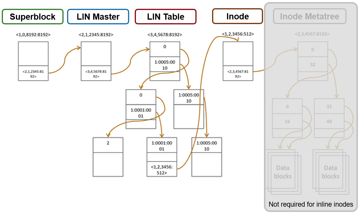
Access starts with the Superblock, which is located at multiple fixed block addresses on each drive in the cluster. The Superblock contains the address locations of the LIN Master block, which contains the root of the LIN B+ Tree (LIN table). The LIN B+Tree maps logical inode numbers to the actual inode addresses on disk, which, in the case of an inlined file, also contains the data. This saves the overhead of finding the address locations of the file’s data blocks and retrieving data from them.
For hybrid nodes with sufficient SSD capacity, using the metadata-write SSD strategy automatically places inlined small files on flash media. However, because the SSDs on hybrid nodes default to 512byte formatting, when using metadata read/write strategies, you must set the ‘–force-8k-inodes’ flag for these SSD metadata pools in order for files to be inlined. This can be a useful performance configuration for small file HPC workloads, such as EDA, for data that is not residing on an all-flash tier. But keep in mind that forcing 8KB inodes on a hybrid pool’s SSDs will result in a considerable reduction in available inode capacity than would be available with the default 512 byte inode configuration.
You can use the OneFS ‘isi_drivenum’ CLI command to verify the drive block sizes in a node. For example, the following output for a PowerScale Gen6 H-series node shows drive Bay 1 containing an SSD with 4KB physical formatting and 512byte logical sizes, and Bays A to E comprising hard disks (HDDs) with both 4KB logical and physical formatting.
# isi_drivenum -bz
Bay 1  Physical Block Size: 4096     Logical Block Size:   512
Bay 2  Physical Block Size: N/A     Logical Block Size:   N/A
Bay A0 Physical Block Size: 4096     Logical Block Size:   4096
Bay A1 Physical Block Size: 4096     Logical Block Size:   4096
Bay A2 Physical Block Size: 4096     Logical Block Size:   4096
Bay B0 Physical Block Size: 4096     Logical Block Size:   4096
Bay B1 Physical Block Size: 4096     Logical Block Size:   4096
Bay B2 Physical Block Size: 4096     Logical Block Size:   4096
Bay C0 Physical Block Size: 4096     Logical Block Size:   4096
Bay C1 Physical Block Size: 4096     Logical Block Size:   4096
Bay C2 Physical Block Size: 4096     Logical Block Size:   4096
Bay D0 Physical Block Size: 4096     Logical Block Size:   4096
Bay D1 Physical Block Size: 4096     Logical Block Size:   4096
Bay D2 Physical Block Size: 4096     Logical Block Size:   4096
Bay E0 Physical Block Size: 4096     Logical Block Size:   4096
Bay E1 Physical Block Size: 4096     Logical Block Size:   4096
Bay E2 Physical Block Size: 4096     Logical Block Size:   4096
Note that the SSD disk pools used in PowerScale hybrid nodes that are configured for meta-read or meta-write SSD strategies use 512 byte inodes by default. This can significantly save space on these pools, because they often have limited capacity, but it will prevent data inlining from occurring. By contrast, PowerScale all-flash nodepools are configured by default for 8KB inodes.
The OneFS ‘isi get’ CLI command provides a convenient method to verify which size inodes are in use in a given node pool. The command’s output includes both the inode mirrors size and the inline status of a file.
When it comes to efficiency reporting, OneFS 9.3 provides three CLI improved tools for validating and reporting the presence and benefits of data inlining, namely:
- The ‘isi statistics data-reduction’ CLI command has been enhanced to report inlined data metrics, including both a capacity saved and an inlined data efficiency ratio:
# isi statistics data-reduction
                      Recent Writes Cluster Data Reduction
                           (5 mins)
--------------------- ------------- ----------------------
Logical data                 90.16G                 18.05T
Zero-removal saved                0                      -
Deduplication saved           5.25G                624.51G
Compression saved             2.08G                303.46G
Inlined data saved            1.35G                  2.83T
Preprotected physical        82.83G                 14.32T
Protection overhead          13.92G                  2.13T
Protected physical           96.74G                 26.28T
Zero removal ratio         1.00 : 1                      -
Deduplication ratio        1.06 : 1               1.03 : 1
Compression ratio          1.03 : 1               1.02 : 1
Data reduction ratio       1.09 : 1               1.05 : 1
Inlined data ratio         1.02 : 1               1.20 : 1
Efficiency ratio           0.93 : 1               0.69 : 1
Be aware that the effect of data inlining is not included in the data reduction ratio because it is not actually reducing the data in any way – just relocating it and protecting it more efficiently. However, data inlining is included in the overall storage efficiency ratio.
The ‘inline data saved’ value represents the count of files which have been inlined, multiplied by 8KB (inode size). This value is required to make the compression ratio and data reduction ratio correct.
- The ‘isi_cstats’ CLI command now includes the accounted number of inlined files within /ifs, which is displayed by default in its console output.
# isi_cstats
Total files                 : 397234451
Total inlined files         : 379948336
Total directories           : 32380092
Total logical data          : 18471 GB
Total shadowed data         : 624 GB
Total physical data         : 26890 GB
Total reduced data          : 14645 GB
Total protection data       : 2181 GB
Total inode data            : 9748 GB
Current logical data        : 18471 GB
Current shadowed data       : 624 GB
Current physical data       : 26878 GB
Snapshot logical data       : 0 B
Snapshot shadowed data      : 0 B
Snapshot physical data      : 32768 B
Total inlined data savings  : 2899 GB
Total inlined data ratio    : 1.1979 : 1
Total compression savings   : 303 GB
Total compression ratio     : 1.0173 : 1
Total deduplication savings : 624 GB
Total deduplication ratio   : 1.0350 : 1
Total containerized data    : 0 B
Total container efficiency  : 1.0000 : 1
Total data reduction ratio  : 1.0529 : 1
Total storage efficiency    : 0.6869 : 1
Raw counts
{ type=bsin files=3889 lsize=314023936 pblk=1596633 refs=81840315 data=18449 prot=25474 ibyte=23381504 fsize=8351563907072 iblocks=0 }
{ type=csin files=0 lsize=0 pblk=0 refs=0 data=0 prot=0 ibyte=0 fsize=0 iblocks=0 }
{ type=hdir files=32380091 lsize=0 pblk=35537884 refs=0 data=0 prot=0 ibyte=1020737587200 fsize=0 iblocks=0 }
{ type=hfile files=397230562 lsize=19832702476288 pblk=2209730024 refs=81801976 data=1919481750 prot=285828971 ibyte=9446188553728 fsize=17202141701528 iblocks=379948336 }
{ type=sdir files=1 lsize=0 pblk=0 refs=0 data=0 prot=0 ibyte=32768 fsize=0 iblocks=0 }
{ type=sfile files=0 lsize=0 pblk=0 refs=0 data=0 prot=0 ibyte=0 fsize=0 iblocks=0 }- The ‘isi get’ CLI command can be used to determine whether a file has been inlined. The output reports a file’s logical ‘size’, but indicates that it consumes zero physical, data, and protection blocks. There is now also an ‘inlined data’ attribute further down in the output that also confirms that the file is inlined.
# isi get -DD file1
* Size:              2
* Physical Blocks:  0
* Phys. Data Blocks: 0
* Protection Blocks: 0
* Logical Size:      8192
PROTECTION GROUPS
* Dynamic Attributes (6 bytes):
*
ATTRIBUTE           OFFSET SIZE
Policy Domains      0      6
INLINED DATA
0,0,0:8192[DIRTY]#1
So, in summary, some considerations and recommended practices for data inlining in OneFS 9.3 include the following:
- Data inlining is opportunistic and is only supported on node pools with 8KB inodes.
- No additional software, hardware, or licenses are required for data inlining.
- There are no CLI or WebUI management controls for data inlining.
- Data inlining is automatically enabled on applicable nodepools after an upgrade to OneFS 9.3 is committed.
- However, data inlining occurs for new writes and OneFS 9.3 does not perform any inlining during the upgrade process. Any applicable small files are instead inlined upon their first write.
- Since inode inlining is automatically enabled globally on clusters running OneFS 9.3, OneFS recognizes any diskpools with 512 byte inodes and transparently avoids inlining data on them.
- In OneFS 9.3, data inlining is not performed on regular files during tiering, truncation, upgrade, and so on.
- CloudPools Smartlink stubs, sparse files, and writable snapshot files are also not candidates for data inlining in OneFS 9.3.
- OneFS shadow stores do not apply data inlining. As such:
- Small file packing is disabled for inlined data files.
- Cloning works as expected with inlined data files.
- Inlined data files do not apply deduping. Non-inlined data files that are once deduped will not inline afterwards.
- Certain operations may cause data inlining to be reversed, such as moving files from an 8KB diskpool to a 512 byte diskpool, forcefully allocating blocks on a file, sparse punching, and so on.
The new OneFS 9.3 data inlining feature delivers on the promise of small file storage efficiency at scale, providing significant storage cost savings, without sacrificing performance, ease of use, or data protection.
Author: Nick Trimbee
Related Blog Posts

OneFS Small File Data Inlining
Tue, 16 Nov 2021 19:41:09 -0000
|Read Time: 0 minutes
OneFS 9.3 introduces a new filesystem storage efficiency feature that stores a small file’s data within the inode, rather than allocating additional storage space. The principal benefits of data inlining in OneFS include:
- Reduced storage capacity utilization for small file datasets, generating an improved cost per TB ratio
- Dramatically improved SSD wear life
- Potential read and write performance improvement for small files
- Zero configuration, adaptive operation, and full transparency at the OneFS file system level
- Broad compatibility with other OneFS data services, including compression and deduplication
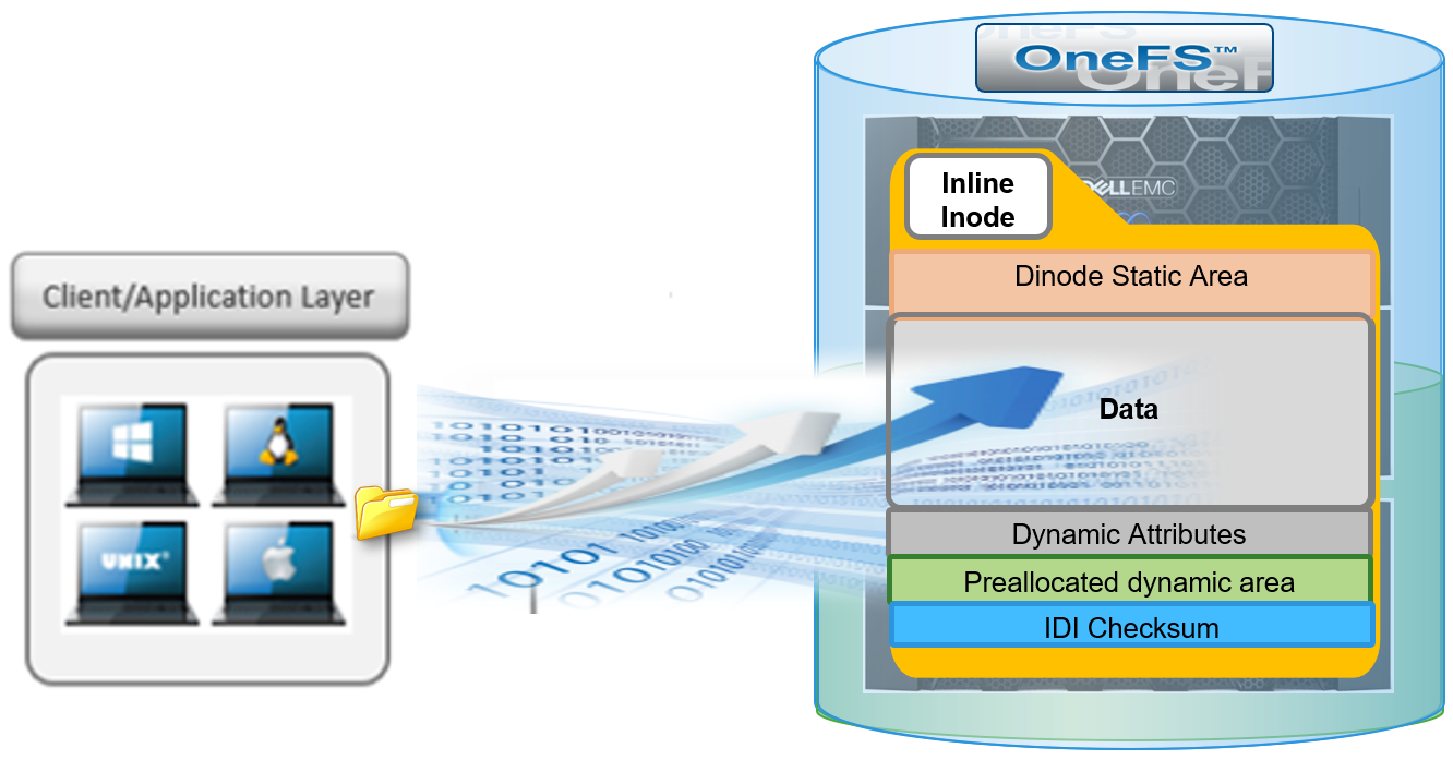
Data inlining explicitly avoids allocation during write operations because small files do not require any data or protection blocks for their storage. Instead, the file content is stored directly in unused space within the file’s inode. This approach is also highly flash media friendly because it significantly reduces the quantity of writes to SSD drives.
OneFS inodes, or index nodes, are a special class of data structure that store file attributes and pointers to file data locations on disk. They serve a similar purpose to traditional UNIX file system inodes, but also have some additional unique properties. Each file system object, whether it be a file, directory, symbolic link, alternate data stream container, or shadow store, is represented by an inode.
Within OneFS, SSD node pools in F series all-flash nodes always use 8KB inodes. For hybrid and archive platforms, the HDD node pools are either 512 bytes or 8KB in size, and this is determined by the physical and logical block size of the hard drives or SSDs in a node pool.
There are three different styles of drive formatting used in OneFS nodes, depending on the manufacturer’s specifications:
Drive Formatting | Characteristics |
Native 4Kn (native) | A native 4Kn drive has both a physical and logical block size of 4096B. |
512n (native) | A drive that has both physical and logical size of 512 is a native 512B drive. |
512e (emulated) | A 512e (512 byte-emulated) drive has a physical block size of 4096, but a logical block size of 512B. |
If the drives in a cluster’s nodepool are native 4Kn formatted, by default the inodes on this nodepool will be 8KB in size. Alternatively, if the drives are 512e formatted, then inodes by default will be 512B in size. However, they can also be reconfigured to 8KB in size if the ‘force-8k-inodes’ setting is set to true.
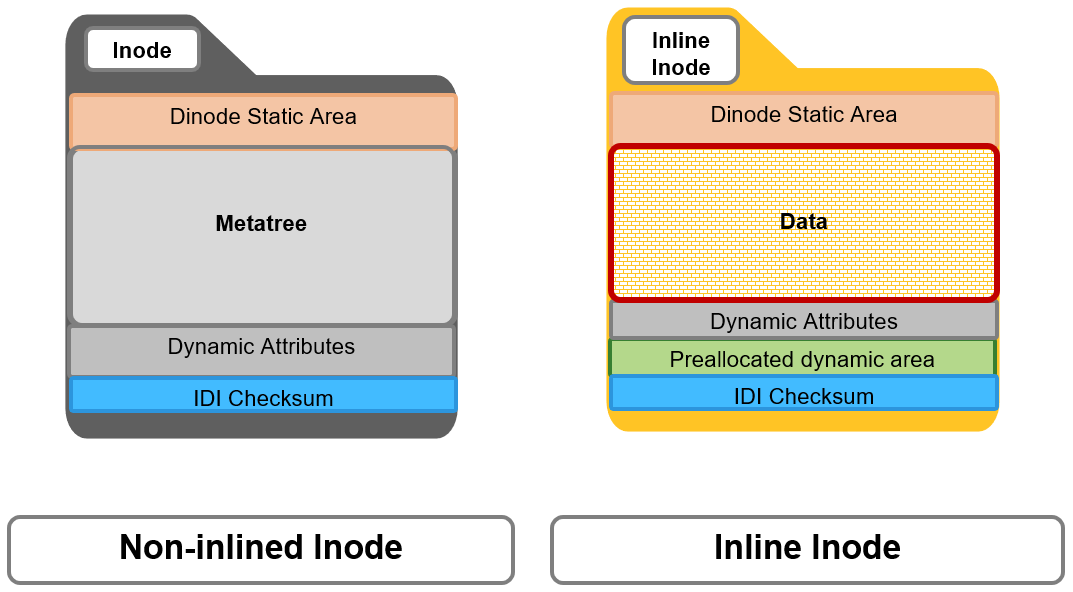
A OneFS inode is composed of several sections. These include:
- A static area, which is typically 134 bytes in size and contains fixed-width, commonly used attributes like POSIX mode bits, owner, and file size.
- Next, the regular inode contains a metatree cache, which is used to translate a file operation directly into the appropriate protection group. However, for inline inodes, the metatree is no longer required, so data is stored directly in this area instead.
- Following this is a preallocated dynamic inode area where the primary attributes, such as OneFS ACLs, protection policies, embedded B+ Tree roots, timestamps, and so on, are cached.
- And lastly a sector where the IDI checksum code is stored.
When a file write coming from the writeback cache, or coalescer, is determined to be a candidate for data inlining, it goes through a fast write path in BSW (BAM safe write - the standard OneFS write path). Compression will be applied, if appropriate, before the inline data is written to storage.

The read path for inlined files is similar to that for regular files. However, if the file data is not already available in the caching layers, it is read directly from the inode, rather than from separate disk blocks as with regular files.

Protection for inlined data operates the same way as for other inodes and involves mirroring. OneFS uses mirroring as protection for all metadata because it is simple and does not require the additional processing overhead of erasure coding. The number of inode mirrors is determined by the nodepool’s achieved protection policy, according to the following table:
OneFS Protection Level | Number of Inode Mirrors |
+1n | 2 inodes per file |
+2d:1n | 3 inodes per file |
+2n | 3 inodes per file |
+3d:1n | 4 inodes per file |
+3d:1n1d | 4 inodes per file |
+3n | 4 inodes per file |
+4d:1n | 5 inodes per file |
+4d:2n | 5 inodes per file |
+4n | 5 inodes per file |
Unlike file inodes above, directory inodes, which comprise the OneFS single namespace, are mirrored at one level higher than the achieved protection policy. The root of the LIN Tree is the most critical metadata type and is always mirrored at 8x.
Data inlining is automatically enabled by default on all 8KB formatted nodepools for clusters running OneFS 9.3, and does not require any additional software, hardware, or product licenses in order to operate. Its operation is fully transparent and, as such, there are no OneFS CLI or WebUI controls to configure or manage inlining.
In order to upgrade to OneFS 9.3 and benefit from data inlining, the cluster must be running a minimum OneFS 8.2.1 or later. A full upgrade commit to OneFS 9.3 is required before inlining becomes operational.
Be aware that data inlining in OneFS 9.3 does have some notable caveats. Specifically, data inlining will not be performed in the following instances:
- When upgrading to OneFS 9.3 from an earlier release which does not support inlining
- During restriping operations, such as SmartPools tiering, when data is moved from a 512 byte diskpool to an 8KB diskpool
- Writing CloudPools SmartLink stub files
- On file truncation down to non-zero size
- Sparse files (for example, NDMP sparse punch files) where allocated blocks are replaced with sparse blocks at various file offsets
- For files within a writable snapshot
Similarly, in OneFS 9.3 the following operations may cause inlined data inlining to be undone, or spilled:
- Restriping from an 8KB diskpool to a 512 byte diskpool
- Forcefully allocating blocks on a file (for example, using the POSIX ‘madvise’ system call)
- Sparse punching a file
- Enabling CloudPools BCM (BAM cache manager) on a file
These caveats will be addressed in a future release.
Author: Nick Trimbee

Setting Up PowerScale for Google Cloud SmartConnect
Wed, 29 Dec 2021 17:48:23 -0000
|Read Time: 0 minutes
In the Dell EMC PowerScale for Google Cloud solution, OneFS uses the cluster service FQDN as its SmartConnect Zone name with a round-robin client-connection balancing policy. The round-robin policy is a default setting and is recommended for most cases in OneFS. (For more details about the OneFS SmartConnect load-balancing policy, see the Load Balancing section of the white paper Dell EMC PowerScale: Network Design Considerations.)
After the cluster is deployed, you must find the OneFS SmartConnect service IP in the clusters page within Google Cloud Console. Then, configure your DNS server to delegate the cluster service FQDN zone to the OneFS Service IP. You need to configure a forwarding rule in Google Cloud DNS which forwards the cluster service FQDN query to the DNS server, and set up a zone delegation on the DNS server that points to the cluster service IP. The following figure shows the DNS query flow by leveraging Google Cloud DNS along with a DNS server in the project.
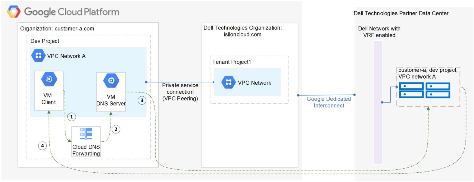
- VM clients send a DNS request for Cluster service FQDN to the Google Cloud DNS service.
- Google Cloud DNS forwards the request to the DNS server.
- The DNS server forwards the request to the cluster service IP. The service IP is responsible for translating the cluster service IP into an available node IP.
- SmartConnect returns a node IP to the client. The client can now access cluster data.
Because Google Cloud DNS cannot communicate with the OneFS cluster directly, we use a DNS server that is located in the authorized VPC network to forward the SmartConnect DNS request to the cluster. You can use either a Windows server or a Linux server. In this blog we use a Windows server to show the detailed steps.
Obtain required cluster information
The following information is required before setting up SmartConnect:
- Cluster service FQDN -- This is the OneFS SmartConnect zone name used by clients.
- Service IP -- This is the OneFS SmartConnect service IP that is responsible for resolving the client DNS request and returning an available node IP to clients.
- Authorized network -- By default, only the machines on an authorized VPC network can access a PowerScale cluster.
To obtain this required information, do the following:
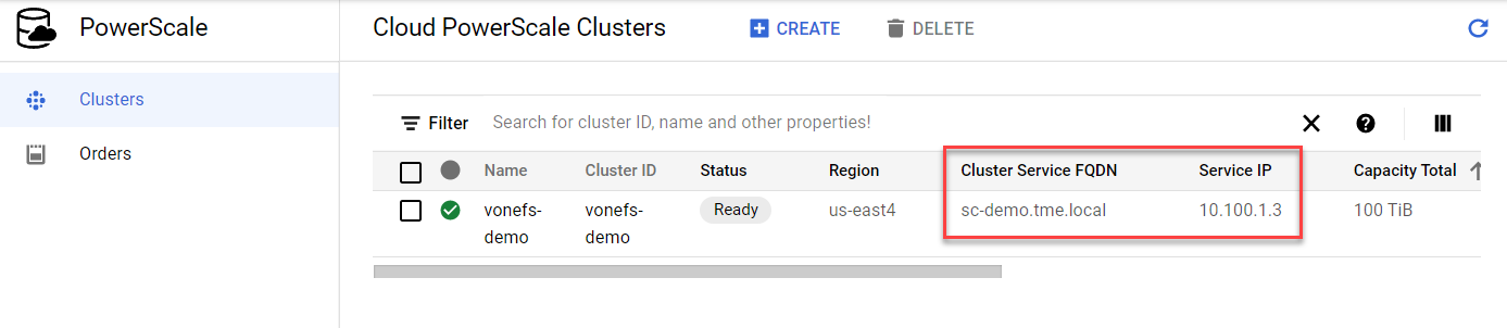
- In the Google Cloud Console navigation menu, click PowerScale and then click Clusters.
- Find your cluster row, where you can see the cluster service FQDN and service IP:
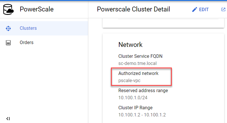
3. To find the authorized network information, click the name of the cluster. From the PowerScale Cluster Details page, find the authorized network from the Network information, highlighted here:
Set up a DNS server
If you already have an available DNS server that is connected to the cluster authorized network, you can use this existing DNS server and skip Step 1 and Step 2 below.
- In the Google Cloud Console navigation menu, click Compute Engine and then click VM instances. In this example, we are creating a Windows VM instance as a DNS server. Make sure your DNS server is connected to the cluster authorized network.
- Log into the DNS server and install DNS Server Role in the Windows machine. (If you are using a Linux machine, you can use Bind software instead.)
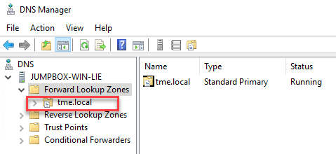
- Create a new DNS zone in the DNS server:
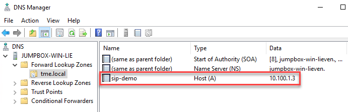
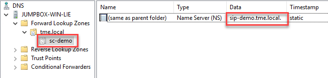
4. Create an (A) record for the cluster service IP. (See the section DNS delegation best practices of the white paper Dell EMC PowerScale: Network Design Considerations for more details.)
5. Create a new delegation for your cluster service FQDN (sc-demo.tme.local in this example) and point the delegation server to your cluster service IP (A) record created above (sip-demo.tme.local in this example), as shown here:
Configure Cloud DNS and firewall rules
- In the Google Cloud Console navigation menu, click Network services and then click Cloud DNS.
- Click the CREATE ZONE button.
- Choose the Private zone type and enter your Cluster Service FQDN in the DNS name field. Choose Forward queries to another server and your cluster authorized network, as shown here:
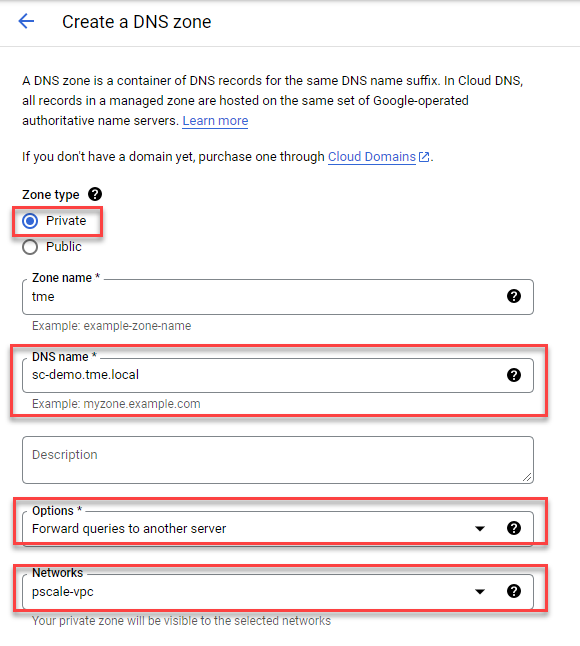
4. Obtain the DNS server IP address that you configured in the ‘Set up a DNS server’ step.
5. Point the destination DNS server to your own DNS server IP address, then click the Create button.

6. Add firewall rules to allow ingress DNS traffic to your DNS server from Cloud DNS. In the Google Cloud Console navigation menu, click VPC network and then click Firewall.
7. Click the CREATE FIREWALL RULE button.
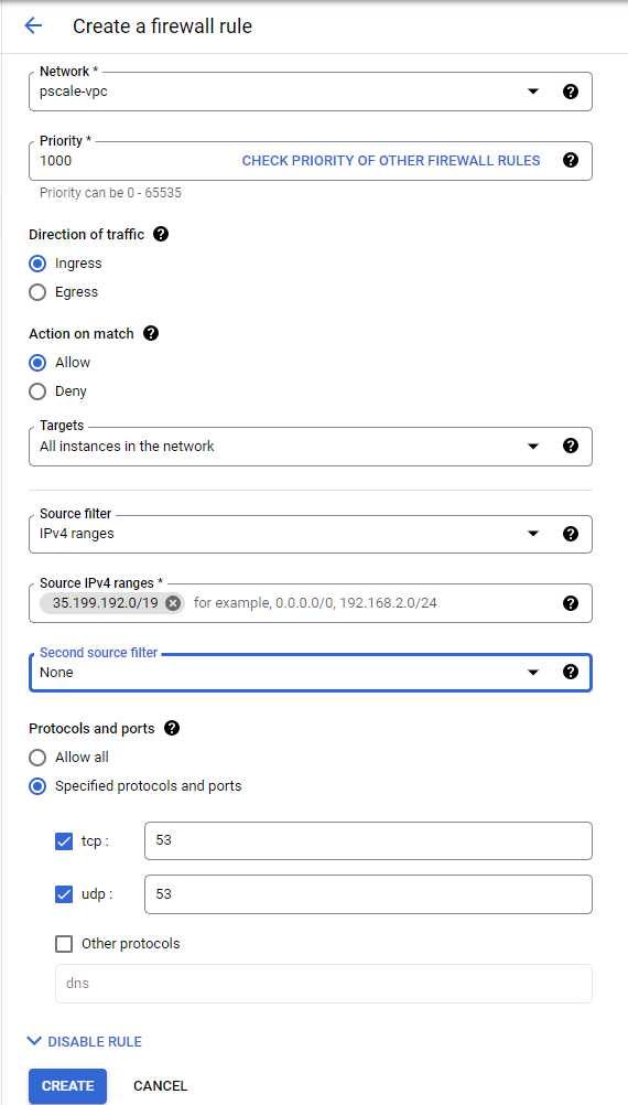
8. Create a new Firewall rule and include the following options:
- In the Network field, make sure the cluster authorized network is selected.
- Source filter: IPv4 ranges
- Source IPv4 ranges: 35.199.192.0/19. This is the IP range Cloud DNS requests will originate from. See Cloud DNS zones overview for more details.
- Protocols and ports: TCP 53 and UDP 53.
See the following example:
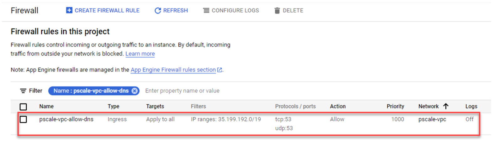
4. The resulting firewall rule in Google Cloud will appear as follows:
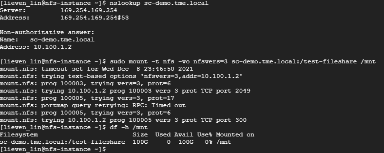
Verify your SmartConnect
- Log into a VM instance that is connected to an authorized network. (This example uses a Linux machine.)
- Resolve the cluster service FQDN via nslookup and mount a file share via NFS.
Conclusion
PowerScale cluster is a distributed file system composed of multiple nodes. We always recommend using the SmartConnect feature to balance the client connections to all cluster nodes. This way, you can maximize PowerScale cluster performance to provide maximum value to your business. Try it now in your Dell EMC PowerScale for Google Cloud solution.
Author: Lieven Lin