


OMNI Bulk Configuration Spreadsheet Part 2 of 2
Wed, 01 Dec 2021 19:07:54 -0000
|Read Time: 0 minutes
In part 2 of the Bulk Configuration blog, we will cover the creation of several server interface profiles using the Bulk Configuration spreadsheet.
Note: See the OMNI User Guide on the Dell EMC OpenManage Network Integration for VMware vCenter website for more details on other configuration options with the Bulk Configuration spreadsheet.
Gather server information
In this section, we will gather the MAC addresses associated with the vmnics of the ESXi hosts. OMNI requires the MAC address of the vmnics to facilitate automation for additional network creation. Once the initial server profiles are created, you can update or modify the interfaces using the server interface profiles, or through the configuration of the vDS in vCenter. OMNI monitors the vDS port group information and applies any changes made to port-groups on the physical network using the MAC addresses associated with the vmnics of the ESXi hosts.
There are two methods that can be used to gather the vmnic MAC addresses:
- Use the show lldp neighbors command on the switch CLI
- Use the ESXi Direct Console User Interface (DCUI)
Show LLDP neighbors
This section covers the use of the switch CLI to get the required MAC addresses.
- From the CLI of the SFS switch, enter the show lldp neighbors command to get the MAC address for the correct server.
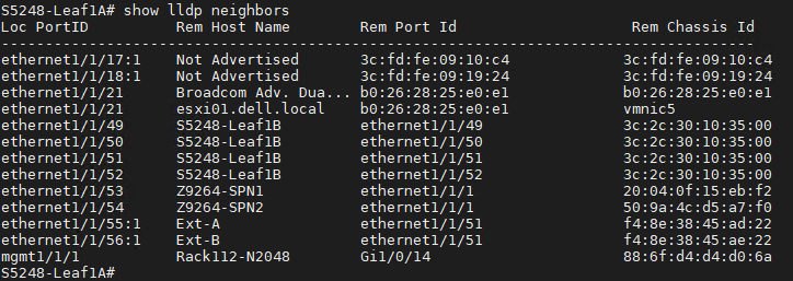
- Run the same command on each leaf switch to gather all MAC addresses associated with the required ESXi servers.
In this example, there is one connection to each leaf switch for the single ESXi host, esxi01. It is connected to ethernet 1/1/21 in the figure above.ESXi01 - NIC1
Leaf1A
b0262825e0e1
- NIC2
Leaf1B
b0262825e0e0
ESXi DCUI
Alternately, you can use the DCUI to get the details on the network adapters.
- Go to the specific server DCUI.
- Select the Configure Management Network option.
- Select Network Adapters.
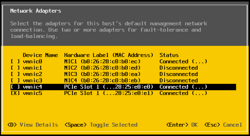
Note: If the full MAC is not visible, enter D to view the full details.
ESXi01 - NIC1 | b0262825e0e1 |
- NIC2 | b0262825e0e0 |
Create server interface profiles
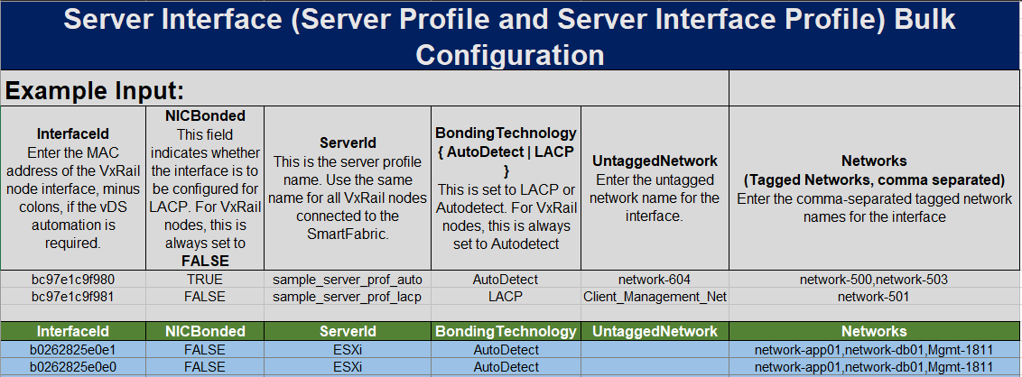
Now that all the MAC addresses have been gathered, enter the information into the Bulk Configuration spreadsheet. In this example, we are applying the previously created networks to a single ESXi server. For details, refer to Bulk Config Spreadsheet Part 1.
- Open the Bulk Configuration spreadsheet.
- Go to the ServerInterface tab.
- Enter the MAC address as the InterfaceId.
- Set the NICBonded type. This example uses False.
- Set a server profile name, ESXi.
- Set the Bonding Technology, AutoDetect.
- Set the Network Tagging. This example will set both networks 100 and 200 as tagged.
Note: The server interface profile uses the NetworkID field to set the tagging. Refer to the appropriate network tab in the spreadsheet or go to the OMNI UI to get the correct NetworkID. If there are existing networks associated with these interfaces, they must be included in the spreadsheet, as the spreadsheet will override the existing configuration on those interfaces.
- Save the spreadsheet. You can now upload the spreadsheet to create the server interface profiles and set the correct network tagging on the switch interfaces.
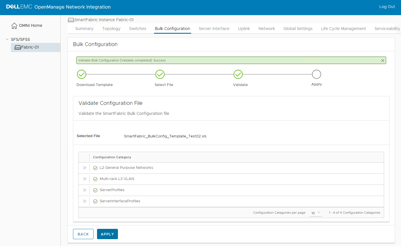
- From the OMNI UI, click the Bulk Configuration tab.
- Upload the spreadsheet and select Validate.
- Click Apply.
Note: If the networks from the Bulk Config Spreadsheet Part 1 blog are still in the spreadsheet, OMNI will revalidate those sections of the spreadsheet.
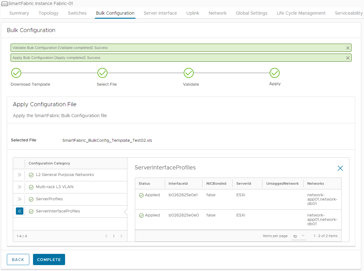
Validate the configuration
The final step will be to validate the configuration on the Fabric. This can be done in one of two ways:
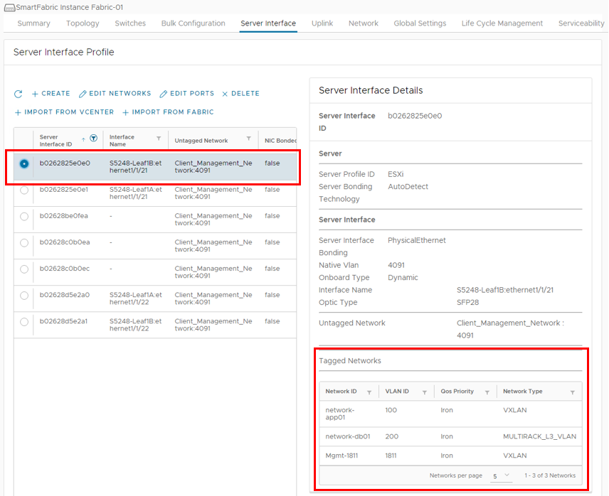
- Use the Server Interface tab in the OMNI UI.
- Use the MAC addresses to locate the correct server profiles. When the specific MAC address is selected, the associated networking configurations can be seen.
The changes made in this example are highlighted with the red boxes.
- Use the switch CLI.
- Use the show virtual network vlan command to verify General Purpose networks.
The network changes specified in the Bulk Configuration spreadsheet can be seen below, highlighted in yellow.
S5248-Leaf1A# show virtual-network vlan
Vlan                 Virtual Network     Interface
-------------------------------------------------
100                  100                 port-channel1000, ethernet1/1/21
1811                 1811                port-channel1, port-channel1000, ethernet1/1/21, ethernet1/1/22
3939                 3939                port-channel1000
4091                 4091                port-channel1000
-----------Output Truncated----------------------- Use the show vlan command to verify VLAN networks.
S5248-Leaf1A# show vlan
Codes: * - Default VLAN, M - Management VLAN, R - Remote Port Mirroring VLANs,
       @ - Attached to Virtual Network, P - Primary, C - Community, I - Isolated
Q: A - Access (Untagged), T - Tagged
    NUM    Status     Description                     Q Ports
    200    Active     database-01                     T Eth1/1/21
                                                      T Po1000
    4000   Active     vlan4000                        T Po97-98,1000
    4002   Active     vlan4002                        A Po97
    4003   Active     vlan4003                        A Po98
*   4089   Active     vlan4089                        A Po1000
    4090   Active     vlan4090                        T Po1000
    4094   Active                                     T Po1000
Related Blog Posts

OMNI Bulk Configuration Spreadsheet Part 1 of 2
Thu, 02 Dec 2021 15:43:35 -0000
|Read Time: 0 minutes
Today we will cover the use of the new Bulk Configuration spreadsheet offered in OMNI 2.1. The Bulk Configuration spreadsheet will be used to create networks on the Fabric. Refer to the OMNI User Guide on the Dell EMC OpenManage Network Integration for VMware vCenter website for more details on other configuration options with the Bulk Configuration spreadsheet.
Download the SmartFabric bulk configuration template
OMNI 2.1 adds the SmartFabric bulk configuration feature. This feature allows the entry of networks, IP addresses, server interface profiles, and eBGP information into a template in Microsoft Excel (.xls) format that is downloaded from OMNI. After entering the information, the template is uploaded into OMNI and all values are applied in one step. This significantly reduces the number of configuration steps required and saves time.
NOTE: The use of the bulk configuration template is optional. The same information can be entered manually using the OMNI UI as shown in the OpenManage Network Integration for SmartFabric Services User Guide, Release 2.1. The guide is available on the Dell EMC OpenManage Network Integration for VMware vCenter website.
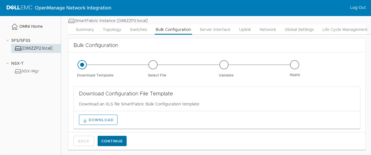
To download the template, perform the following steps:
- In the OMNI UI, select the SmartFabric instance in the left navigation panel.
- In the right navigation panel, select Bulk Configuration and click DOWNLOAD to download the template.
Configure networks
The first section will cover the addition of two different network types.
- General Purpose Network – Layer 2 (L2) or Layer 3 (L3) network that spans all racks in the Fabric.
- Multi-Rack L3 VLAN – L3 network that spans several racks, with a unique IP subnet per rack.
The General Purpose Network is the preferred network type in SmartFabric services. It can be configured as an L2 or L3 network. However, in some situations the Multi-Rack L3 VLAN is a better option. Refer to the Dell EMC Networking SmartFabric Services Deployment for VMware NSX-T deployment guide for more information on the specific use case for the Multi-Rack L3 VLAN.
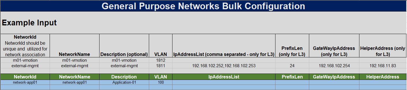
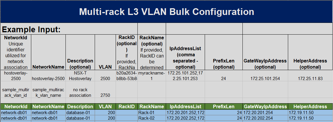
The General Purpose network used for this example has the values shown in the table below.
| Network Type | L2/L3 | NetworkID | Network Name | Description | VLAN |
|---|---|---|---|---|---|
General Purpose | L2 | network-app01 | network-app01 | Application-01 | 100 |
- Enter the specific network information into the Bulk Configuration spreadsheet on the General Purpose Network tab.
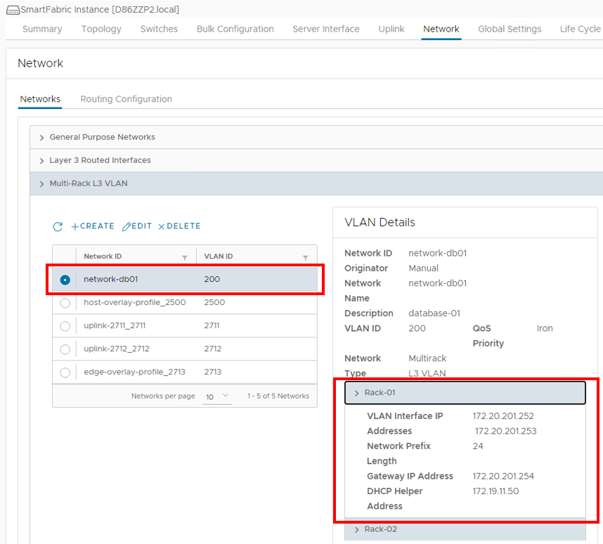
- Enter the information for our next network, which will be a Multi-Rack L3 VLAN. The values used for this example are listed in the table below.
Network Type NetworkID Network Name Description VLAN Rack-Name IP Address List Prefix Gateway IP Address IP Helper Address MultiRack-L3 VLAN network-db01 network-db01 Database-01 200 Rack-01 172.20.201.252,
172.20.201.25324 172.20.201.254 172.19.11.50 network-db01 network-db01 Database-01 200 Rack-02 172.20.201.252,
172.20.201.25324 172.20.201.254 172.19.11.50
- Enter the specific network information into the Bulk Configuration spreadsheet on the Multi-Rack L3 VLAN tab.
- Once all of the information has been put into the Bulk Configuration spreadsheet, save the spreadsheet.
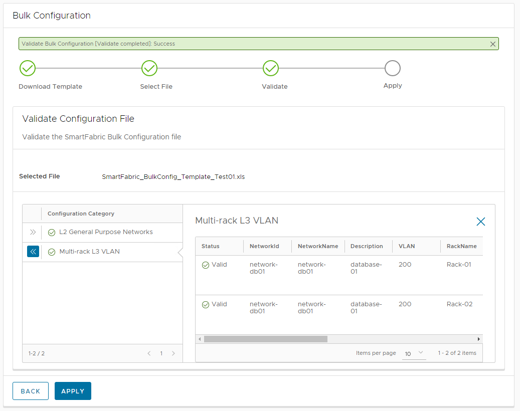
- Navigate back to the OMNI User Interface and upload the saved spreadsheet.
- Click Validate to validate the spreadsheet prior to Fabric configuration.
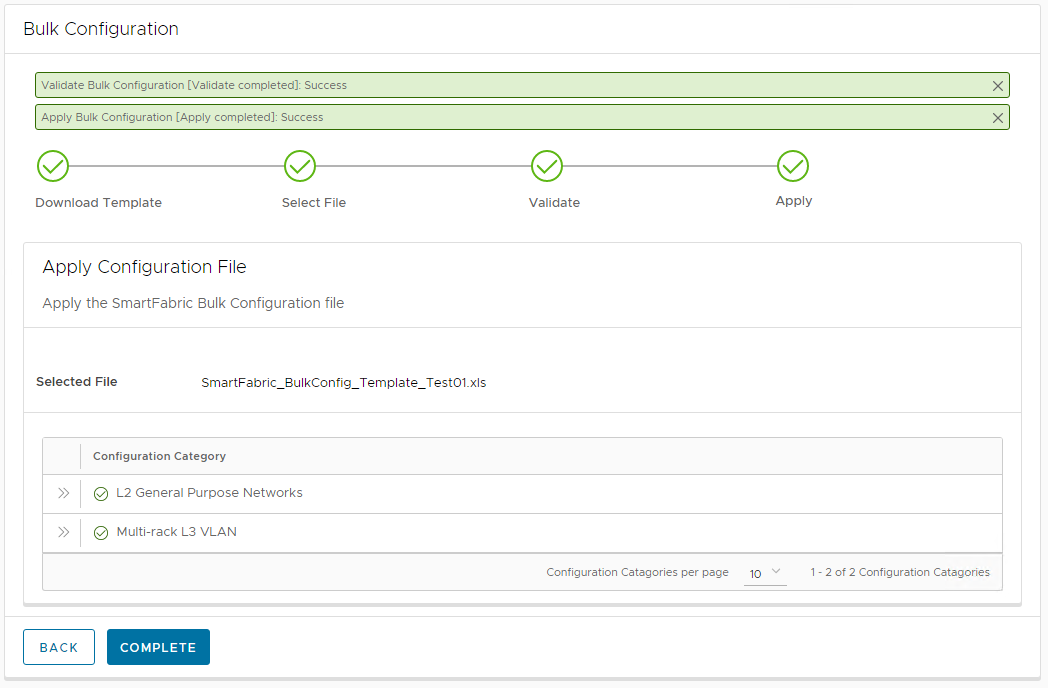
- Click Apply.
- Click Complete.
Validation of network creation
The network creation can be validated in two ways, through the OMNI UI or through the switch CLI.
Validate networks in the OMNI UI
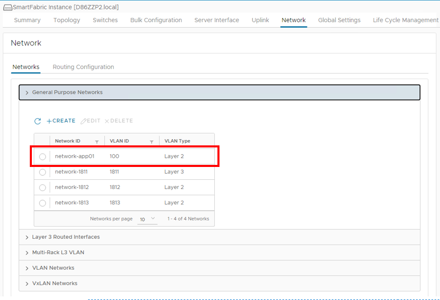
- To validate the networks through the OMNI UI, navigate to the OMNI Network tab.
- Expand the General Purpose Networks or Multi-Rack L3 VLAN tab.
The Application01 network that was specified in the Bulk Configuration spreadsheet can be seen below in the General Purpose Networks section of the OMNI UI.
The Database01 network that was specified in the Bulk Configuration spreadsheet can also be seen below in the Multi-Rack L3 VLAN section of the OMNI UI.
Validate networks in the switch CLI
Optionally, the networks may be validated using the switch CLI.
Navigate to the CLI of switches in the Fabric.
To verify the General Purpose networks, run the show smartfabric networks and show virtual-network vlan command. The output below is for one leaf in the Fabric. The output will be similar on the other leaf switches in the Fabric. The network items that were created using the Bulk Configuration spreadsheet can be seen below highlighted in yellow.
S5248F-Leaf1A# show smartfabric networks Name Type QosPriority NetworkId Vlan ------------------------------------------------------------------------------------------------------------------------------- network-app01 VXLAN IRON network-app01 100 vSAN Network 1813 VXLAN IRON network-1813 1813 uplink-2711_2711 MULTIRACK_L3_VLAN IRON uplink-2711_2711 2711 Client_Management_Network VXLAN IRON Client_Management_Network 4091 network-db01 MULTIRACK_L3_VLAN IRON network-db01 200 -----------------------Output Truncated---------------------------S5248F-Leaf1A# show virtual-network vlan Vlan Virtual Network Interface ------------------------------------------------- 100 100 port-channel1000 1811 1811 port-channel1000, ethernet1/1/1, ethernet1/1/2, ethernet1/1/3 1812 1812 port-channel1000, ethernet1/1/1, ethernet1/1/2, ethernet1/1/3 1813 1813 port-channel1000, ethernet1/1/1, ethernet1/1/2, ethernet1/1/3 3939 3939 port-channel1000, ethernet1/1/1, ethernet1/1/2, ethernet1/1/3 4091 4091 port-channel1000 S5248F-Leaf1A#
To verify the Multi-Rack L3 VLAN networks, run the show smartfabric networks and show vlan command. The output below is for one leaf in the Fabric. The output will be similar on the other leaf switches in the Fabric.
S5248F-Leaf1A# show smartfabric networks
Name                          Type                   QosPriority         NetworkId                               Vlan
--------------------------------------------------------------------
network-app01                 VXLAN                  IRON                network-app01                           100
vSAN Network 1813             VXLAN                  IRON                network-1813                            1813
uplink-2711_2711              MULTIRACK_L3_VLAN      IRON                uplink-2711_2711                        2711
Client_Management_Network     VXLAN                  IRON                Client_Management_Network               4091
network-db01                  MULTIRACK_L3_VLAN      IRON                network-db01                            200
-----------------------Output Truncated---------------------------
Note: The output of the show vlan command will not reflect the Multi-Rack L3 VLAN, if the networks are not applied to an interface through the server interface profiles in OMNI.
S5248F-Leaf1B# show vlan
Codes: * - Default VLAN, M - Management VLAN, R - Remote Port Mirroring VLANs,
       @ - Attached to Virtual Network, P - Primary, C - Community, I - Isolated
Q: A - Access (Untagged), T - Tagged
    NUM    Status     Description             Q Ports
    200    Active     database-01             T Eth1/1/2
    2500   Active                             T Eth1/1/1-1/1/3
                                              T Po1000
    2712   Active     vlan2712                T Eth1/1/1-1/1/3
    2713   Active                             T Eth1/1/1-1/1/3
                                              T Po1000
    4000   Active     vlan4000                T Po96-97,1000
    4001   Active     vlan4001                A Po96
    4002   Active     vlan4002                A Po97
*   4089   Active     vlan4089                A Po1000
    4090   Active     vlan4090                T Po1000
    4094   Active                             T Po1000
S5248F-Leaf1B#

SmartFabric Services Integration with VMware NSX-T
Tue, 13 Sep 2022 23:30:11 -0000
|Read Time: 0 minutes
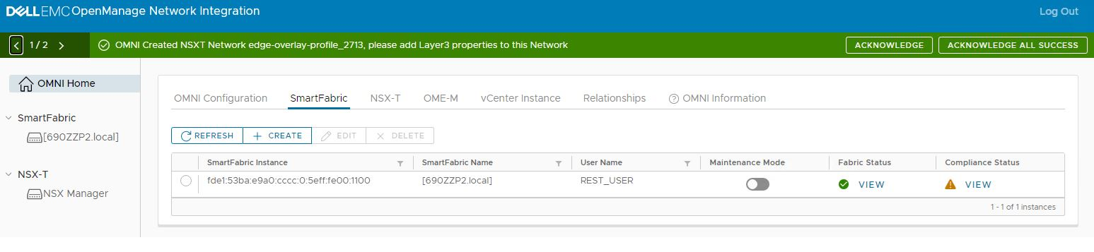
SmartFarbic Services (SFS) is automation software that is built into Dell EMC SmartFabric OS10. Open Manage Network Integration (OMNI) is an orchestration appliance that allows for the integration of SFS with various solutions and provides a single pane of management for multiple fabrics and solutions.
Note: For more information on SFS, see the Dell EMC SmartFabric Services blog, or the Dell EMC OpenManage Network Integration (OMNI) blog.
One of the solutions that OMNI is engineered to integrate with is VMware NSX-T Manager. The integration allows OMNI to automatically configure the physical underlay with the specific networking values that have been configured in the NSX-T Manager. The NSX-T Manager is deployed and configured for all relevant values, transport zones, uplink and transport profiles, transport nodes, tier-0 and tier-1 routers, and any segments. Once NSX-T is fully configured, it is integrated with OMNI. OMNI then reads the values in the NSX-T Manager and configures all Layer 3 (L3) VLANs and any BGP routing configurations.
Once OMNI configures the physical underlay with the values pulled from the NSX-T Manager, the user needs to go to the networks section of OMNI and add the relevant IP addresses to the host overlay and edge overlay networks. The required IP addresses for the uplink networks are automatically pulled from the NSX-T Manager and applied to the fabric.
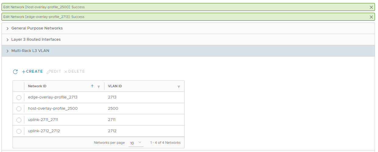 Image Caption
The example topology below uses a leaf-spine fabric for performance and scalability. SFS automates the deployment of this fabric, and OMNI automates the networking requirements for the NSX-T overlay.
NOTE: Step-by-step deployment of the SFS and VxRail environment is detailed in Dell EMC Networking SmartFabric Services Deployment with VxRail Deployment Guide. This NSX-T deployment uses L3 routed uplinks from the leaf switches in Rack 1 to the external switches.
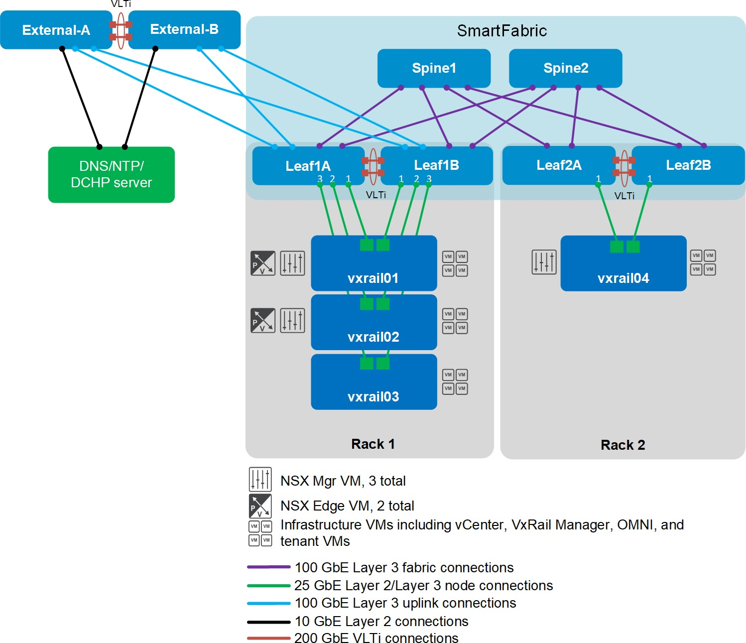 With SFS, two leaf switches are used in each rack for redundancy and performance. A Virtual-Link Trunking interconnect (VLTi) connects each pair of leaf switches. Every leaf switch has an L3 uplink to every spine switch. Equal-Cost Multi-Path routing (ECMP) is leveraged to use all available bandwidth on the leaf-spine connections.
SFS uses BGP-EVPN and VXLAN to stretch Layer 2 (L2) networks across the L3 leaf-spine fabric. This allows for the scalability of L3 networks with the VM mobility benefits of an L2 network. For example, a VM can be migrated from one rack to another without the need to change its IP address and gateway information.
Each VxRail node has two network adapter ports. The ports carry Management, VSAN, vMotion, and NSX-T traffic.
For high-availability, VMware recommends you deploy a cluster of three NSX Manager VMs and a cluster of two NSX Edge VMs. VM host rules are configured to keep the NSX Manager and NSX Edge VMs on separate hosts.
An additional rule is created to keep NSX Edge VMs on hosts that connect to the border leafs. The border leafs provide the physical uplink connections to the external network.
Only the NSX Edge VMs need to be on VxRail nodes in a specific rack. NSX Manager VMs, infrastructure VMs (such as vCenter Server, VxRail Manager, and OMNI), and tenant (or user) VMs may be on VxRail nodes in different racks as needed.