


Direct from Development - PowerEdge MX7000 Direct Orthogonal Connectors
Tue, 10 Nov 2020 16:54:16 -0000
|Read Time: 0 minutes
Summary
The trend of increasingly higher- power processors and DIMMs creates challenges for traditional midplane architectures, particularly with regard to airflow and cooling, high speed signal transmission, and power delivery.
The new PowerEdge MX7000 modular platform eliminates the midplane and instead uses Direct Orthogonal Connectors for internal interconnection of compute, storage and switch modules.
Elimination of the midplane greatly optimizes airflow and enhances cooling. Signal transmission and power delivery are also improved by this new, innovative design.
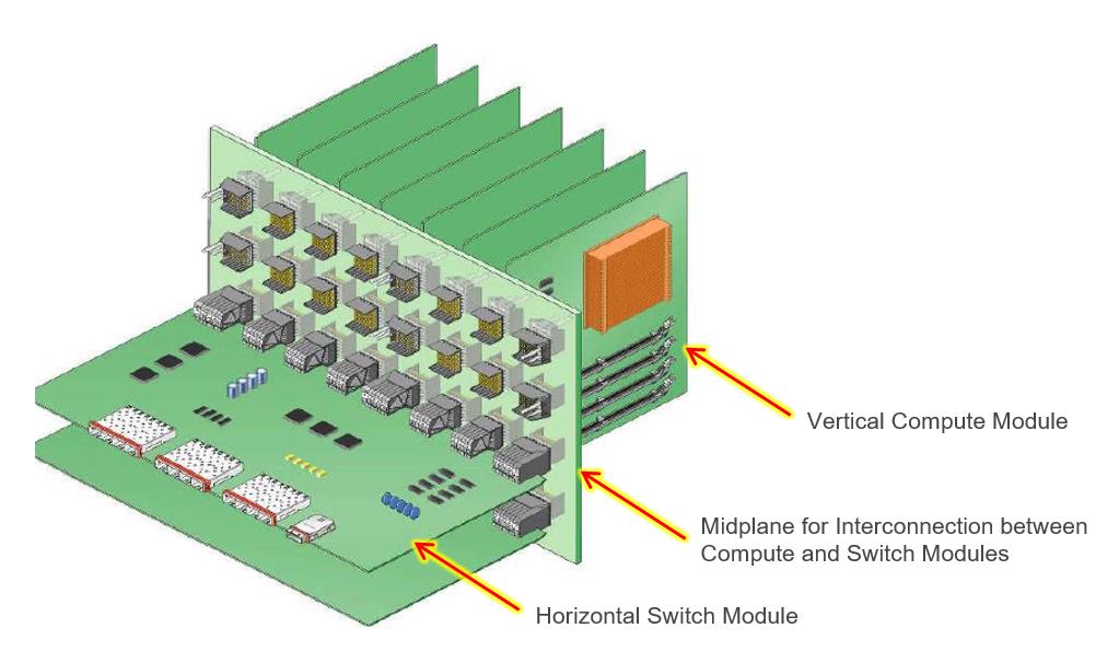
Modular systems (such as the Dell EMC PowerEdge M1000e blade enclosure) integrating both compute/storage modules and switch (I/O) modules require an intricate method of interconnection within the chassis. A traditional interconnect architecture contains vertical compute/storage modules and horizontal switch modules, and a midplane enabling interconnection between these modules, as shown in Figure 1 below.

Figure 1: A traditional interconnect architecture using a midplane for interconnection of compute and switch (I/O) modules
A traditional midplane architecture such as the above has been an effective means of interconnect for many generations of servers, but a number of design challenges have been apparent and need to be overcome. Airflow has been a key challenge. Proper airflow is critical in order to ensure cooling of the compute modules, especially with current and future systems with high-power processors and DIMM’s. One attempt to resolve this has been to incorporate vent holes into the midplane to allow airflow. However, due to signal and power routing within the midplane, properly sized and effective placement of the vent holes is not always feasible. Moreover, signal integrity (SI) may be impacted when routing high speed signal traces long distances within the midplane. Even the use of Low Loss PCB material (such as Megtron 6) for high speed signal traces has limitations.
Consequently, in the development of the PowerEdge MX7000 Modular Chassis, the elimination of the midplane was a key design goal to improve airflow and signal integrity. To accomplish this, the implementation of Direct Orthogonal Connectors was selected to provide the interconnection between compute modules and switch modules. Fundamentally, Orthogonal Connectors provide a direct, right angle interconnection between a vertical PWA (Printed Wiring Assembly, also known as a Printed Circuit Board Assembly, PCBA) such as a compute module, and a horizontal PWA, i.e. a switch module, without a midplane. This direct interconnection is shown in Figure 2 below:
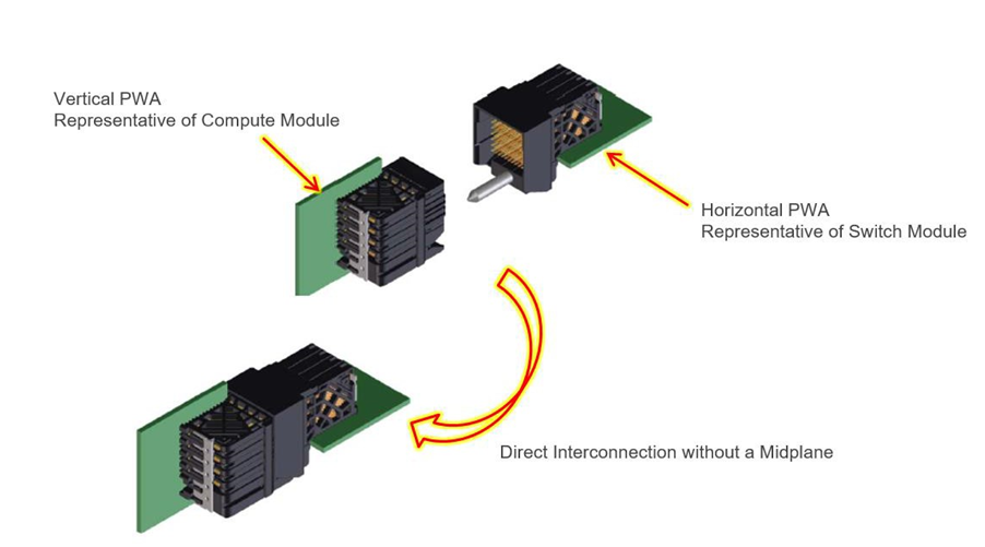
Figure 2: The PowerEdge MX7000 Orthogonal Connectors enable direct interconnection of compute/storage and switch (I/O) modules, liberating the architecture from the encumbrances and cost of a midplane.
The use of direct orthogonal connectors in the MX7000 eliminates airflow impedance caused by a midplane, and enhances overall airflow and cooling. The schematic in Figure 3 below illustrates how eliminating the midplane opens up internal areas of the PowerEdge MX7000 and improves airflow:
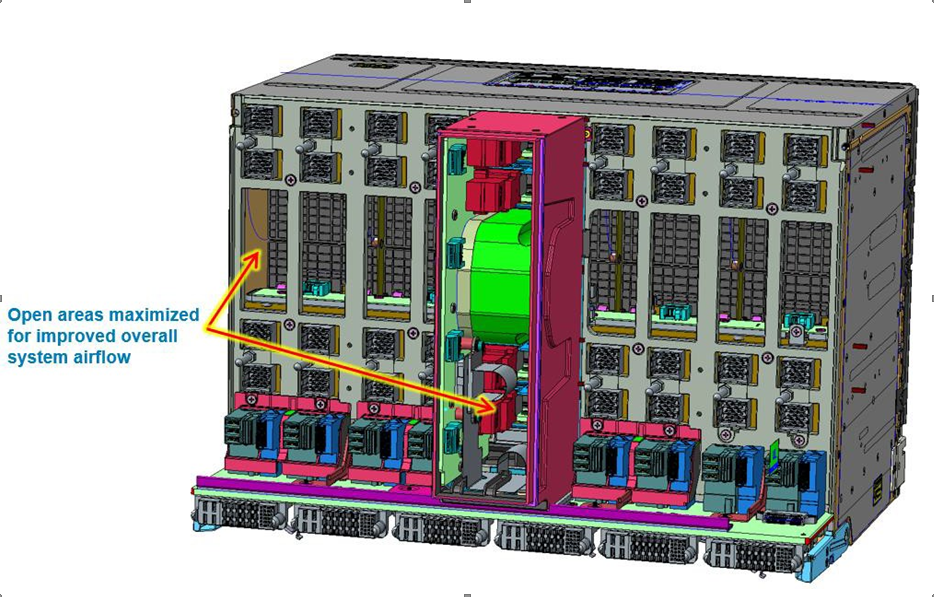
Figure 3: Elimination of the midplane in the PowerEdge MX7000 architecture opens up internal areas to improve airflow.
In addition to improving airflow and enhancing cooling, use of Direct Orthogonal Connectors in the PowerEdge MX7000 enables the formation of a comprehensive interconnection for high speed signal transmission between compute/storage modules and switch (I/O) modules, as well as for effective power delivery to these modules. Figure 4 below illustrates direct orthogonal interconnections between a vertical Compute Module and horizontal Switch Module, as well as power delivery using both Vertical and Horizontal Power Distribution PWA’s to those modules:
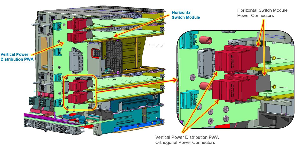
Figure 4: Schematic showing orthogonal power connectors for horizontal switch modules and vertical compute/storage modules.
Conclusion
While earlier servers and modular systems relied on a traditional midplane architecture, implementation of innovative Direct Orthogonal Connectors in the new PowerEdge MX7000 eliminates the midplane and greatly optimizes airflow through the compute and switch modules. This enhances cooling and ensures that current and future high-power processors and DIMM’s can be cooled more effectively, even at high ambient temperatures. Additionally, signal integrity will be optimal without being compromised by long Printed Circuit Board (PCB) traces, allowing for high speed signals (including PCIe Gen 4).
- For more information about airflow and cooling in the new PowerEdge MX7000, including its Multiple Airflow Zone design, see the Direct from Development tech note, PowerEdge MX7000 Chassis Thermal Airflow Architecture.
Related Blog Posts

Direct from Development – PowerEdge MX7000 At the Box Serial Access
Thu, 12 Nov 2020 19:26:21 -0000
|Read Time: 0 minutes
Summary
PowerEdge MX7000 comes with a Management Module that provides chassis management. This technical white paper describes the step by step “at- the-box” serial access feature of the chassis management firmware. A typical use of the serial access feature is for troubleshooting purpose when remote access to the management firmware is not available.
Preparation
What you need?
To prepare for serial access, you need the correct cable for connection. You will need a “micro-USB to USB” cable (Figure-1) long enough to connect your client system to the micro-USB port in the Management Module.
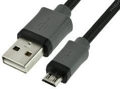
Figure 1 USB to Micro USB Cable
Where to connect?
The micro-USB port (Figure-2) for serial access is in the Management Module located at the rear of the chassis. If you see two Management Modules, look for the module that has the LED under “i” lit.
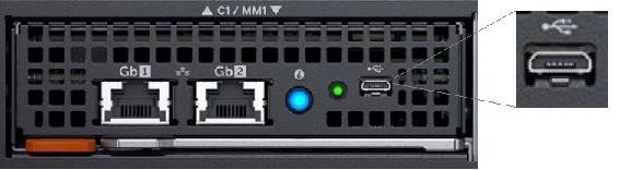
Figure 2 - Micro USB port to connect to
What you need in the client?
You can use any serial terminal client application of your choice, such as Tera Term or PuTTY.
Windows Client Host
If your client host system is running Windows, the default serial device driver should work. Open the Device Manager (type “devmgmt.msc” from command line) to determine which COM port Windows has created for your serial connection.
If Windows is not able to see the serial COM port or it is present but you are not able to connect, you may have to manually install the device driver. You can get this driver from a 3rd party vendor. Search for “cypress semiconductor usb serial driver download”. Look for the driver download link. After the manual driver installation, you should see the COM port for your connection (example in Figure-3).
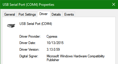
Figure 3 – 3rd party serial device driver in Windows
Linux Client Host
If your client host system is running Linux, the device driver to connect to the serial interface should already be installed. There is an extra step however that is required to correctly recognize the Management Module serial device.
The USB serial device is recognized by Linux as a “Thermometer” device and loads the cytherm kernel module. The following steps help to correctly recognize the Management Module serial device.
First, add this entry “blacklist cytherm” to the file “/etc/modprobe.d/blacklist.conf”. This will prevent loading the incorrect driver.
Next, connect the serial cable to the host system. If you have already connected the serial cable, you will need to unload the incorrect driver with the command “sudo rmmod cytherm”. Then re-connect the serial cable to the host system.
If you see “/dev/ttyACM0” then you are ready to connect. The “0” means it is the first serial device discovered.
Serial Console
Serial Console Menu
When a serial connection is established to the Management Module, the serial client application will be presented with the serial console’s main menu (Figure-4). It is populated with the available components to which serial connection can be made. On the upper right corner of the menu, it shows which Management Module you are connected to (the Active or the Standby). When you are finished, you may simply disconnect the cable and exit the serial client application.
The following sections describe each selection in the Main menu.
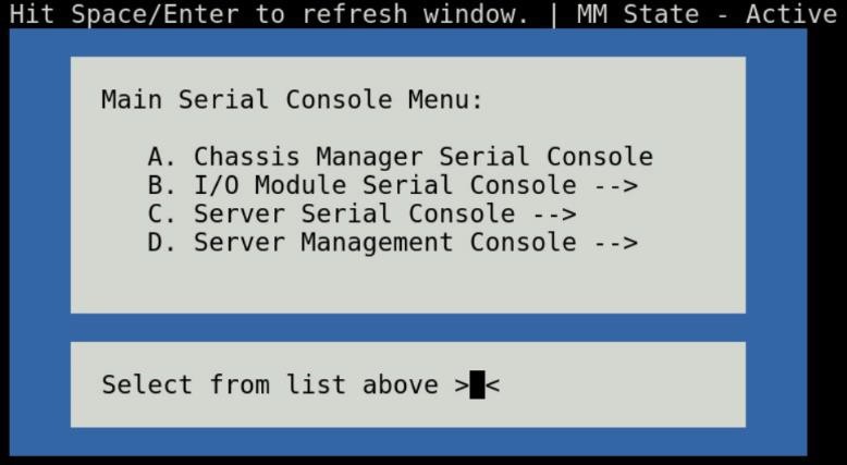
Figure 4 - Main menu
Chassis manager firmware console
Choosing option (A) from the Main menu takes you to the Chassis Manager firmware console. A serial session will open and a login prompt is displayed.
On successful login, you will have access to the Chassis Manager’s firmware racadm interface. To end the session, the exit sequence is “Ctrl-A Ctrl-X”. If using minicom in Linux, the exit sequence is “Ctrl-A Ctrl-A Ctrl-X”. Upon exit, you will see the Main menu.
I/O module firmware console
Choosing option (B) from the Main menu takes you to the I/O Module Console menu (Figure-5). The menu shows you the available I/O modules that support the serial interface.
Prior to selecting an I/O module, you will have the option to toggle the connection mode to either “binary” or non-binary” using option (B) from the menu. In “binary” mode, the terminal control characters from the client application are passed through the serial session.
Upon selection of an I/O module, a serial session will open and a login prompt is displayed. On successful login, you will have access to the I/O module firmware command line.
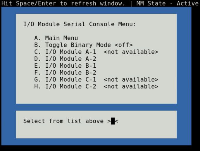
Figure 5 - I/O module console menu
To end a non-binary session, the exit sequence is “Ctrl-\”.
To end a binary session requires an extra step. The extra step is to login to the Chassis Manager’s web interface and go to Home > Troubleshoot > Terminate Serial Connection.
Server serial console
Choosing option (C) from the Main menu takes you to the Sled Host Serial Console menu (Figure-6). The menu shows you the available server host in a sled present in the chassis.
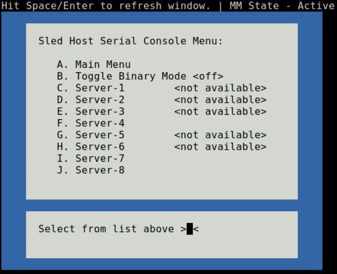
Figure 6 - Sled host serial menu
Prior to selecting a server sled, you will have the option to toggle the connection mode to either “binary” or non-binary” using option (B) from the menu. In “binary” mode, the terminal control characters from the client application are passed through the serial session.
Upon selection of a server sled, you will get access to the serial command line interface of the operating system running on the sled.
To end a non-binary session, the exit sequence is “Ctrl-\”. This exit sequence can be configured from the sled’s iDRAC UI.
To end a binary session requires an extra step. The extra step is to login to the Chassis Manager’s web interface and go to Home > Troubleshoot > Terminate Serial Connection.
Server management firmware console
Choosing option (D) from the Main menu takes you to the iDRAC Serial Console menu (Figure-7). The menu shows you the available iDRAC present in the chassis. iDRAC is the systems management firmware for a compute sled.
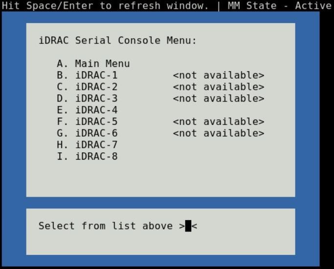
Figure 7- iDRAC console menu

Direct from Development – PowerEdge MX7000 LED Device Status
Thu, 12 Nov 2020 19:10:27 -0000
|Read Time: 0 minutes
Summary
The MX7000 chassis and modular devices in a MX7000 chassis are equipped with multi- purpose LEDs which can indicate the current health state of the device, provide identification or implement device specific features.
This whitepaper intends to provide a single point of comprehensive status information for LED behaviors on PowerEdge MX7000.
Users want to be able to look at the chassis and deduce its current health state when physically in front of the chassis. Most of the components that are present in the MX7000 chassis are able to display their current health state via LEDs.
Users also want to be able to accurately identify components in a chassis. A useful feature to do this is the Identify function that can be activated from the front panel, or remotely via the OpenManage Enterprise Modular GUI. This can be a very useful feature when you are managing a multi- chassis setup and want to remotely identify a particular device in the pool.
Some devices also implement their own specific LED behavior, for example PowerEdge MX5016s implement an LED feature that indicates mapping state. This document will cover these features.
Management Module LED Behavior
The Management Module (MM) is located at the rear of the chassis (Figure 1) and contains two LEDs: Power LED (Green only) and Status LED/Button (Blue or Amber).
Status LED/Button (Blue or Amber) is on the left and the Power LED (Green only) is on the right as shown by red highlights.
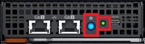
Figure 1: Management Module
The Power and Status LED (color is dependent on status) states are as follows:
Healthy Chassis
MM State | Power LED State | Status LED State |
Active | LED ON (Green) | LED ON (Blue-solid) |
Standby | LED ON (Green) | LED OFF |
Identify (Active) | LED ON (Green) | LED ON (Blue-blinking) |
Faulted Chassis
MM State | Power LED State | Status LED State |
Active | LED ON (Green) | LED ON (Amber-blinking) |
Identify (Active) | LED ON (Green) | LED ON (Blue-blinking) |
(Note: Only active MM will reflect faulted chassis state and provide identification functionality.)
Management Module Hardware Failure
Issue | Power LED State | Status LED State |
MM unable to power on | LED OFF | LED OFF |
MM unable to boot up | LED OFF | LED ON (Amber-solid) |
The Status LED/Button on the rear of the chassis changes to AMBER when any of the Front Panel iconic indicators shows AMBER. When the chassis/MM is in Identify State, the combo Status LED/Button shall always blink BLUE and override any other Status LED state.
IO Module LED Behavior
I/O Modules (IOMs) are inserted in the rear of the chassis and support a two-stacked arrangement of LEDS: Top = AMBER/GREEN, Bottom = BLUE.
Figure 2a – Typical Fab A/B IO Module: Power/Status LED on the top and Identification LED on bottom as shown by red highlights.

Figure 2b – Typical Fab C IO Module: Power/Status LED on the top and Identification LED on bottom as shown by red highlights.
The LEDs support the following functions:
IOM Health | Power/Status LED State | Identification LED State |
Healthy | LED ON (Green) | - |
Faulted | LED ON (Amber) | - |
Identify | - | LED ON (Blue-blinking) |
The green LED behavior can be overridden to indicate fabric mismatch. In case there is a fabric mismatch, green LED will blink for 2.5 seconds and then stay lit.
Sled LED Behavior
The Sleds are inserted in the front of the chassis and contain an LED for Power/Status/Identification via Blue or Amber colors.
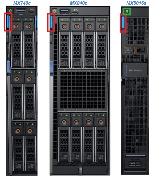
Figure 3: Current PowerEdge MX Sled Options
The Power/Status/Identification LED is on the top left highlighted in red.
The Power/Status/Identification (color is dependent on status) LED states for a sled device will be as follows:
Chassis manager firmware console
Sled Health | Power/Status/Identification LED State |
Off | LED_OFF |
Healthy | LED ON (Blue) |
Errors exist (System on/off) | LED ON (Amber-blinking) |
Identify | LED ON (Blue-blinking) |
Failsafe | LED ON (Amber-solid) |
For PowerEdge MX5016s (Figure 3), a cylindrical LED is also available marked with green highlight in the figure. Its behavior is as follows:
Mapping state | Cylinder LED on PowerEdge MX5016s |
Mapped to Compute that is powered ON | LED ON (Blinking) |
Unmapped | LED OFF |
All mapped compute sleds are off | LED OFF |
NOTE: It is unsafe to remove the PowerEdge MX5016s any time the LED is Blinking, as it is has active mappings to compute sleds that are powered on. To remove the PowerEdge MX5016s, either unmap storage from all compute sleds, or power down all compute sleds that are using this storage. See the User Guide for more information.
PSU LED Behavior
The Power Supply Units (PSUs) are inserted in the front of the chassis and utilize four LEDs: 3 on the front (figure below, left) and 1 in the back (figure below, right).

Figure 4 - Front and Rear PSU LEDs
The PSU LED states are as follows:
PSU State | Health LED (Front) | AC Present (Front) | DC Present (Front) | AC Present (Rear) |
Healthy | LED ON (Green) | LED ON | LED ON | LED ON |
Faulted | LED ON (Amber) | - | - | - |
On the front of the PSU, if the AC Present LED is illuminated, then AC is detected and within tolerance. If the DC Present LED is illuminated, then the PSU is supplying DC to the chassis. The AC Present LED on the rear of the chassis, when illuminated, indicates that AC is detected.
FAN LED Behavior
The Fans are inserted in the front and the back of the chassis (Figure 8) and contain one LED: Power/Status LED (Green or Amber).
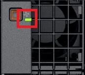
Figure 6 – Front Fans Power/Status LED
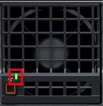
Figure 7 – Rear Fans Power/Status LED
The Power/Status/Identification (color is dependent on status) LED states will be as follows:
Fan Health | Power/Status LED State |
Off | LED_OFF |
Healthy | LED ON (Green) |
Fault | LED ON (Amber-blinking) |
Firmware Update in Progress | LED ON (Green-blinking) |
Conclusion: A thorough understanding of the physical LED status can ensure efficient health status and provide feedback for timely troubleshooting. The PowerEdge MX management module, compute sleds, storage sleds, IO Modules, power supply, and fans, each have LED state indicators that deliver identification on specific features.