


Direct from Development - PowerEdge MX7000 Chassis Thermal Airflow Architecture
Tue, 10 Nov 2020 23:06:50 -0000
|Read Time: 0 minutes
Summary
Creating a modular infrastructure that can efficiently cool the high-power, high- density workloads of today and tomorrow requires intelligent, scalable design.
Dell EMC’s PowerEdge MX7000 modular infrastructure meets these thermal challenges through an innovative, patent- pending chassis architecture design.
The Multiple Airflow Zone architecture of the new MX7000 chassis enables enhanced energy efficiency in the cooling of higher power and denser system configurations, extends the lifecycle of the chassis to accommodate multiple generations of future IT technology, and delivers excellent investment protection.
Modular infrastructures enable customers to be flexible in configuration, agile in management, and efficient in design, over several generations of compute, storage, and networking needs. The unique thermal design of the new Dell EMC PowerEdge MX7000 chassis ensures that customers can confidently grow over many generations of IT technology, satisfying forthcoming demands for scalable expansion and performance while providing excellent investment protection. The multiple airflow zone architecture of the MX7000 is engineered to ensure fresh air is delivered to each component of the chassis, enabling enhanced cooling of higher power and dense system configurations.
Chassis Architecture
The overall chassis architecture of the PowerEdge MX7000 uses dedicated, independent airflow paths for each critical subsystem (Compute, I/O, and Power Supplies) to provide fresh air to each individual zone. This design allows for expanded feature support, improved cooling efficiency, and the flexibility to scale with future needs. Figure 1 below provides a view of the front and rear of the MX7000 chassis with each zone highlighted.
- Zone 1 (Blue): Cooling air for the eight vertically-arranged Compute and Storage sled slots at the front of the chassis is drawn thru the chassis by five horizontally-arranged fans at the rear
- Zone 2 (Yellow): Four vertically arranged fans at the front of the chassis push cooling air into the I/O Modules (IOMs) at the rear of the chassis
- Zone 3 (Green): The bottom of the chassis is populated with up to six power supply units (PSUs) each with a dedicated fan and exhaust airflow path out the rear of the chassis
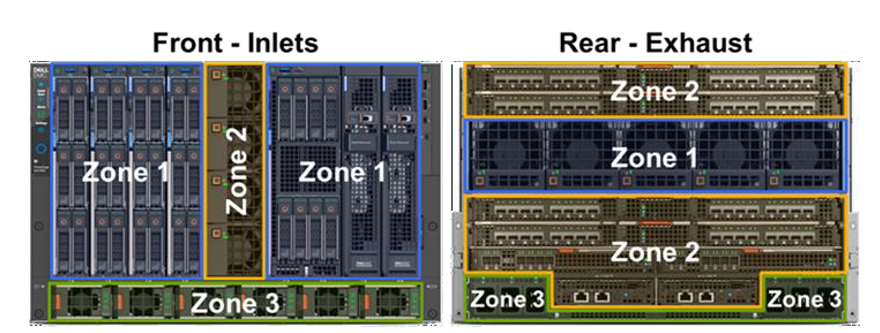
Figure 1: Front and rear view of PowerEdge MX7000 chassis with dedicated airflow zones highlighted
The orthogonal layout of these zones allows for simple, front-to-back airflow thru the chassis. By avoiding overly complex airflow paths to each subsystem, the overall chassis minimizes its impedance, allowing for increased airflow capability compared to traditional modular chassis architectures. Additionally, the independent airflow zones allow for more granular fan control algorithms which increase fan speeds only when and where it is needed to further increase efficiency.
Compute and Storage Sled Cooling
Compared with previous modular chassis from Dell and competitors, the MX7000 chassis contains no vertical midplane that would restrict the airflow through the chassis. Instead, sleds within the chassis mate directly with rear IOMs in A1/A2/B1/B2 slots through direct orthogonal interconnects. In the space between the A1/A2 and B1/B2 IOMs, the MX7000 80mm fan modules are directly ducted to the sleds to pull air through compute and/or storage sleds in Zone 1. Multiple chassis seals ensure that the low pressure generated by the rear 80mm fans stays within Zone 1. Containing the low pressure is critical in enabling the increased sled storage density with support for up to six 2.5” HDDs in the front end of the Dell EMC PowerEdge MX740c.
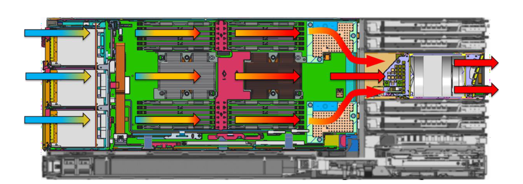
Figure 2 below provides a cross-sectional view of the chassis to highlight the Zone 1 airflow path thru a compute sled. Cool air enters thru the hard disk drive (HDD) bay of the sled before cooling the CPUs, memory, and peripheral components. The 80mm fan modules at the rear of the chassis pull air through the sleds and exhaust hot air out of the system. Fans are positioned in line with the critical heat loads, the CPUs, to avoid complex ducting and provide efficient cooling. Since there are no downstream components in this flow path, a large temperature difference is allowed across CPUs to maximize processor TDP support with headroom to scale with future generations.

Figure 2: Cross-sectional view of airflow through Zone 1 of the MX7000 chassis, showing cooling of Compute sleds. Air enters at front of chassis (on left) and exhausts thru rear of chassis (on right). Other airflow zones have been greyed out in this graphic.
Networking and I/O
Due to their internal layout, modular infrastructures have traditionally been forced to cool networking fabrics with preheated air from upstream components or through tortuous pathways that limit the amount of cooling airflow available. With limited airflow capability, the ability to support future networking and I/O technologies becomes more difficult as these technologies continue to advance at a rapid pace. In contrast, the MX7000 chassis has been designed for fresh inlet air delivery to all rear IOMs and Chassis Management Modules (CMMs) via four dedicated fan modules in the front of the chassis. The direct airflow path is shown in the cross-sectional graphic in Figure 3 (at the top of Page 3), which highlights airflow Zone 2. The four 60mm fan modules arranged vertically share a large plenum down the center of the chassis. An air ducts splits the airflow into an upper path which cools IOMs A1/A2 and a lower path to cool IOMs B1/B2/C1/C2 and CMMs. The fresh air entering these modules ensures the MX7000 chassis can run fans at lower speeds and operate over a wider range of environmental conditions as well as providing sufficient airflow capability for future networking technologies.
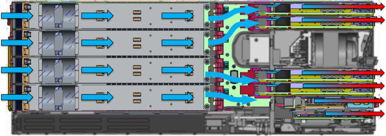
Figure 3: Airflow through Zone 2 of the MX7000 chassis, showing cooling of IOMs. Other airflow zones have been greyed out in this graphic.
Power Supplies
Power supplies in the MX7000 chassis benefit from a simple, independent airflow path at the bottom of the chassis, as shown in the cross sectional view of Figure 4 below. PSUs intake fresh air at the front of the chassis. Dedicated fans in the front of each PSU push airflow through dense electrical components and under the power connector at the back of the PSU. Since there are no downstream components to cool, PSUs can operate with very high exhaust temperatures of 60°C or higher. This thermal design helps ensure reliable delivery of up to 3000W supplied power in the dense form factor of each MX7000 PSU.
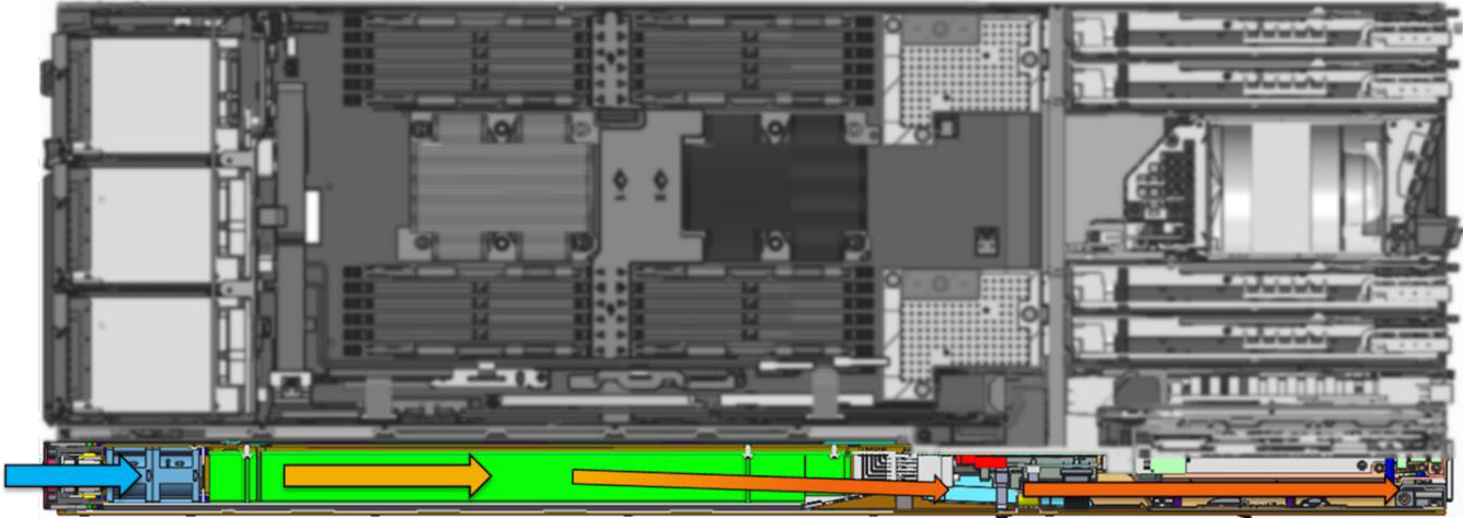
Figure 4: Airflow through Zone 3 of the MX7000 chassis, illustrating cooling of PSUs. Other airflow zones have been greyed out in this graphic
Conclusions
Traditional modular architectures have been characterized by complex airflow pathways that restrict airflow available to cool internal components, or require downstream components to operate within the constraints of preheated air from upstream components. This results in sub-optimal energy efficiency as well as places limitations on feature support, which in turn adversely impacts scalable growth for higher performance and/or capacity expansion.
The innovative multiple airflow zone architecture of the new PowerEdge MX7000 chassis overcomes these challenges and ensures that fresh air is delivered to each component in the chassis, enhancing cooling for higher power and denser system configurations. This design enables increased energy efficiency, extends the lifecycle of the chassis to accommodate multiple generations of future IT technology, and delivers excellent investment protection.
Related Blog Posts

Direct from Development – PowerEdge MX7000 At the Box Serial Access
Thu, 12 Nov 2020 19:26:21 -0000
|Read Time: 0 minutes
Summary
PowerEdge MX7000 comes with a Management Module that provides chassis management. This technical white paper describes the step by step “at- the-box” serial access feature of the chassis management firmware. A typical use of the serial access feature is for troubleshooting purpose when remote access to the management firmware is not available.
Preparation
What you need?
To prepare for serial access, you need the correct cable for connection. You will need a “micro-USB to USB” cable (Figure-1) long enough to connect your client system to the micro-USB port in the Management Module.

Figure 1 USB to Micro USB Cable
Where to connect?
The micro-USB port (Figure-2) for serial access is in the Management Module located at the rear of the chassis. If you see two Management Modules, look for the module that has the LED under “i” lit.
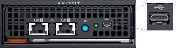
Figure 2 - Micro USB port to connect to
What you need in the client?
You can use any serial terminal client application of your choice, such as Tera Term or PuTTY.
Windows Client Host
If your client host system is running Windows, the default serial device driver should work. Open the Device Manager (type “devmgmt.msc” from command line) to determine which COM port Windows has created for your serial connection.
If Windows is not able to see the serial COM port or it is present but you are not able to connect, you may have to manually install the device driver. You can get this driver from a 3rd party vendor. Search for “cypress semiconductor usb serial driver download”. Look for the driver download link. After the manual driver installation, you should see the COM port for your connection (example in Figure-3).
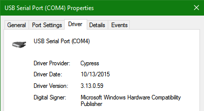
Figure 3 – 3rd party serial device driver in Windows
Linux Client Host
If your client host system is running Linux, the device driver to connect to the serial interface should already be installed. There is an extra step however that is required to correctly recognize the Management Module serial device.
The USB serial device is recognized by Linux as a “Thermometer” device and loads the cytherm kernel module. The following steps help to correctly recognize the Management Module serial device.
First, add this entry “blacklist cytherm” to the file “/etc/modprobe.d/blacklist.conf”. This will prevent loading the incorrect driver.
Next, connect the serial cable to the host system. If you have already connected the serial cable, you will need to unload the incorrect driver with the command “sudo rmmod cytherm”. Then re-connect the serial cable to the host system.
If you see “/dev/ttyACM0” then you are ready to connect. The “0” means it is the first serial device discovered.
Serial Console
Serial Console Menu
When a serial connection is established to the Management Module, the serial client application will be presented with the serial console’s main menu (Figure-4). It is populated with the available components to which serial connection can be made. On the upper right corner of the menu, it shows which Management Module you are connected to (the Active or the Standby). When you are finished, you may simply disconnect the cable and exit the serial client application.
The following sections describe each selection in the Main menu.
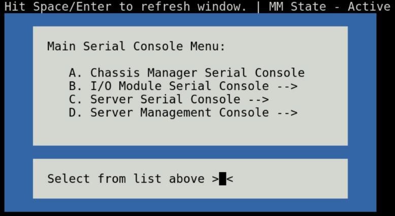
Figure 4 - Main menu
Chassis manager firmware console
Choosing option (A) from the Main menu takes you to the Chassis Manager firmware console. A serial session will open and a login prompt is displayed.
On successful login, you will have access to the Chassis Manager’s firmware racadm interface. To end the session, the exit sequence is “Ctrl-A Ctrl-X”. If using minicom in Linux, the exit sequence is “Ctrl-A Ctrl-A Ctrl-X”. Upon exit, you will see the Main menu.
I/O module firmware console
Choosing option (B) from the Main menu takes you to the I/O Module Console menu (Figure-5). The menu shows you the available I/O modules that support the serial interface.
Prior to selecting an I/O module, you will have the option to toggle the connection mode to either “binary” or non-binary” using option (B) from the menu. In “binary” mode, the terminal control characters from the client application are passed through the serial session.
Upon selection of an I/O module, a serial session will open and a login prompt is displayed. On successful login, you will have access to the I/O module firmware command line.
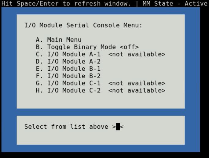
Figure 5 - I/O module console menu
To end a non-binary session, the exit sequence is “Ctrl-\”.
To end a binary session requires an extra step. The extra step is to login to the Chassis Manager’s web interface and go to Home > Troubleshoot > Terminate Serial Connection.
Server serial console
Choosing option (C) from the Main menu takes you to the Sled Host Serial Console menu (Figure-6). The menu shows you the available server host in a sled present in the chassis.
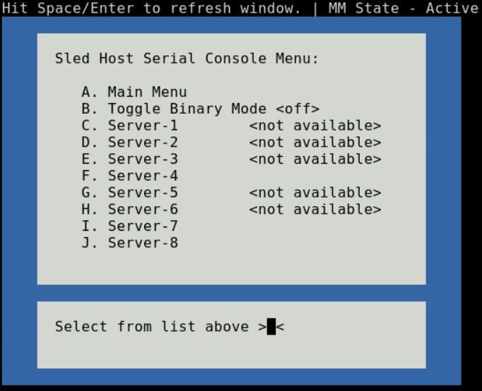
Figure 6 - Sled host serial menu
Prior to selecting a server sled, you will have the option to toggle the connection mode to either “binary” or non-binary” using option (B) from the menu. In “binary” mode, the terminal control characters from the client application are passed through the serial session.
Upon selection of a server sled, you will get access to the serial command line interface of the operating system running on the sled.
To end a non-binary session, the exit sequence is “Ctrl-\”. This exit sequence can be configured from the sled’s iDRAC UI.
To end a binary session requires an extra step. The extra step is to login to the Chassis Manager’s web interface and go to Home > Troubleshoot > Terminate Serial Connection.
Server management firmware console
Choosing option (D) from the Main menu takes you to the iDRAC Serial Console menu (Figure-7). The menu shows you the available iDRAC present in the chassis. iDRAC is the systems management firmware for a compute sled.
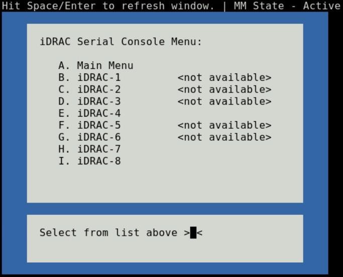
Figure 7- iDRAC console menu

Direct from Development – PowerEdge MX7000 LED Device Status
Thu, 12 Nov 2020 19:10:27 -0000
|Read Time: 0 minutes
Summary
The MX7000 chassis and modular devices in a MX7000 chassis are equipped with multi- purpose LEDs which can indicate the current health state of the device, provide identification or implement device specific features.
This whitepaper intends to provide a single point of comprehensive status information for LED behaviors on PowerEdge MX7000.
Users want to be able to look at the chassis and deduce its current health state when physically in front of the chassis. Most of the components that are present in the MX7000 chassis are able to display their current health state via LEDs.
Users also want to be able to accurately identify components in a chassis. A useful feature to do this is the Identify function that can be activated from the front panel, or remotely via the OpenManage Enterprise Modular GUI. This can be a very useful feature when you are managing a multi- chassis setup and want to remotely identify a particular device in the pool.
Some devices also implement their own specific LED behavior, for example PowerEdge MX5016s implement an LED feature that indicates mapping state. This document will cover these features.
Management Module LED Behavior
The Management Module (MM) is located at the rear of the chassis (Figure 1) and contains two LEDs: Power LED (Green only) and Status LED/Button (Blue or Amber).
Status LED/Button (Blue or Amber) is on the left and the Power LED (Green only) is on the right as shown by red highlights.
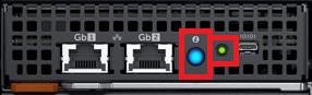
Figure 1: Management Module
The Power and Status LED (color is dependent on status) states are as follows:
Healthy Chassis
MM State | Power LED State | Status LED State |
Active | LED ON (Green) | LED ON (Blue-solid) |
Standby | LED ON (Green) | LED OFF |
Identify (Active) | LED ON (Green) | LED ON (Blue-blinking) |
Faulted Chassis
MM State | Power LED State | Status LED State |
Active | LED ON (Green) | LED ON (Amber-blinking) |
Identify (Active) | LED ON (Green) | LED ON (Blue-blinking) |
(Note: Only active MM will reflect faulted chassis state and provide identification functionality.)
Management Module Hardware Failure
Issue | Power LED State | Status LED State |
MM unable to power on | LED OFF | LED OFF |
MM unable to boot up | LED OFF | LED ON (Amber-solid) |
The Status LED/Button on the rear of the chassis changes to AMBER when any of the Front Panel iconic indicators shows AMBER. When the chassis/MM is in Identify State, the combo Status LED/Button shall always blink BLUE and override any other Status LED state.
IO Module LED Behavior
I/O Modules (IOMs) are inserted in the rear of the chassis and support a two-stacked arrangement of LEDS: Top = AMBER/GREEN, Bottom = BLUE.
Figure 2a – Typical Fab A/B IO Module: Power/Status LED on the top and Identification LED on bottom as shown by red highlights.

Figure 2b – Typical Fab C IO Module: Power/Status LED on the top and Identification LED on bottom as shown by red highlights.
The LEDs support the following functions:
IOM Health | Power/Status LED State | Identification LED State |
Healthy | LED ON (Green) | - |
Faulted | LED ON (Amber) | - |
Identify | - | LED ON (Blue-blinking) |
The green LED behavior can be overridden to indicate fabric mismatch. In case there is a fabric mismatch, green LED will blink for 2.5 seconds and then stay lit.
Sled LED Behavior
The Sleds are inserted in the front of the chassis and contain an LED for Power/Status/Identification via Blue or Amber colors.
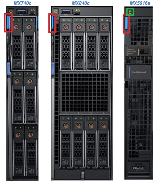
Figure 3: Current PowerEdge MX Sled Options
The Power/Status/Identification LED is on the top left highlighted in red.
The Power/Status/Identification (color is dependent on status) LED states for a sled device will be as follows:
Chassis manager firmware console
Sled Health | Power/Status/Identification LED State |
Off | LED_OFF |
Healthy | LED ON (Blue) |
Errors exist (System on/off) | LED ON (Amber-blinking) |
Identify | LED ON (Blue-blinking) |
Failsafe | LED ON (Amber-solid) |
For PowerEdge MX5016s (Figure 3), a cylindrical LED is also available marked with green highlight in the figure. Its behavior is as follows:
Mapping state | Cylinder LED on PowerEdge MX5016s |
Mapped to Compute that is powered ON | LED ON (Blinking) |
Unmapped | LED OFF |
All mapped compute sleds are off | LED OFF |
NOTE: It is unsafe to remove the PowerEdge MX5016s any time the LED is Blinking, as it is has active mappings to compute sleds that are powered on. To remove the PowerEdge MX5016s, either unmap storage from all compute sleds, or power down all compute sleds that are using this storage. See the User Guide for more information.
PSU LED Behavior
The Power Supply Units (PSUs) are inserted in the front of the chassis and utilize four LEDs: 3 on the front (figure below, left) and 1 in the back (figure below, right).

Figure 4 - Front and Rear PSU LEDs
The PSU LED states are as follows:
PSU State | Health LED (Front) | AC Present (Front) | DC Present (Front) | AC Present (Rear) |
Healthy | LED ON (Green) | LED ON | LED ON | LED ON |
Faulted | LED ON (Amber) | - | - | - |
On the front of the PSU, if the AC Present LED is illuminated, then AC is detected and within tolerance. If the DC Present LED is illuminated, then the PSU is supplying DC to the chassis. The AC Present LED on the rear of the chassis, when illuminated, indicates that AC is detected.
FAN LED Behavior
The Fans are inserted in the front and the back of the chassis (Figure 8) and contain one LED: Power/Status LED (Green or Amber).
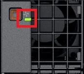
Figure 6 – Front Fans Power/Status LED
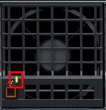
Figure 7 – Rear Fans Power/Status LED
The Power/Status/Identification (color is dependent on status) LED states will be as follows:
Fan Health | Power/Status LED State |
Off | LED_OFF |
Healthy | LED ON (Green) |
Fault | LED ON (Amber-blinking) |
Firmware Update in Progress | LED ON (Green-blinking) |
Conclusion: A thorough understanding of the physical LED status can ensure efficient health status and provide feedback for timely troubleshooting. The PowerEdge MX management module, compute sleds, storage sleds, IO Modules, power supply, and fans, each have LED state indicators that deliver identification on specific features.