


Direct from Development – PowerEdge MX Power Redundancy
Thu, 12 Nov 2020 18:38:08 -0000
|Read Time: 0 minutes
Summary
This blog discusses core details associated with the PowerEdge MX redundant power features. Specifically called out are the grid power options and associated redundancy features.
Power considerations are key to a successful kinetic infrastructure deployment and planning for sufficient power and redundancy. Discussed are the AC & DC options associated with the chassis deployment options.
Shared Power Infrastructure
MX7000 continues Dell EMC’s commitment to maximize performance-per-watt through the consolidation of servers and network switchgear into a single high- density chassis using 14th generation ultra-efficient power supplies and dynamic power-efficient fans.
A shared power infrastructure takes advantage of the aggregation of multiple servers by distributing power across the system without the wasted power margin seen with individual monolithic servers and switchgear. Shared resources allow for a common power policy across all servers in chassis.
The power distribution inside the PowerEdge MX7000 Modular Server System consists of a 3+3 redundant power supply system, located in the rear bottom of the chassis. Each power supply is rated at 3000W bringing total system redundant power is approximately 9000W in a 3+3 power supply configuration. Each power supply unit (PSU) is hot-swappable and are accessed from the front of the chassis with power cables that can stay permanently attached to the rear.
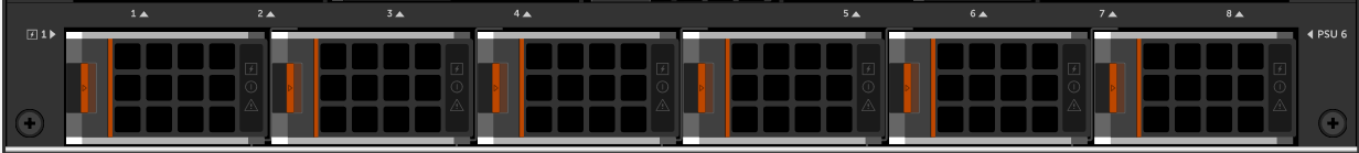
Figure 1 – PSUs Removable from the front of the chassis
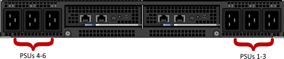
Figure 2 – AC power connected in the rear of the chassis
The chassis power supplies are on a common output bus so that, if any PSU fails, neighbor PSUs can pick up the load. Because of this, there are multiple PSU redundancy modes supported for the MX7000.
If there are two power grids feeding the data center racks, AC Grid Redundancy policy can provide the greatest protection against both AC loss or PSU failure:
- If Power Grid #1 fails, PSUs 4-6 will continue to operate from Power Grid #2
- If Power Grids #1 and #2 are operational, the system can suffer the failure of up to 3 PSUs in a 6-PSU configurations without affecting the operation of the chassis.
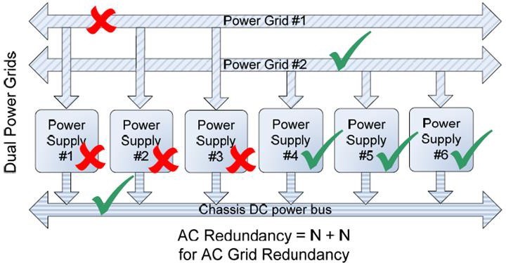
Figure 3 – AC Grid Redundancy – Loss of a power grid allows for uninterrupted operation.
Should either of these failure scenarios occur, the MX7000 will set a fault and can be configured to send notification of the issue.
Whether a single or dual AC Grid is employed, the MX7000 can be configured to support DC Redundancy. This configuration allows for 1 or more PSUs to fail yet keep the chassis fully operational.
As shown in Figure 4, the failure of one PSU will not cause failure of the chassis DC power bus. The likelihood of multiple power supplies failing at the same time is remote. If additional PSU capacity is installed (i.e. installing a fourth PSU in the bottom example of Figure 4), the chassis can suffer multiple PSU failures without affecting system operation.
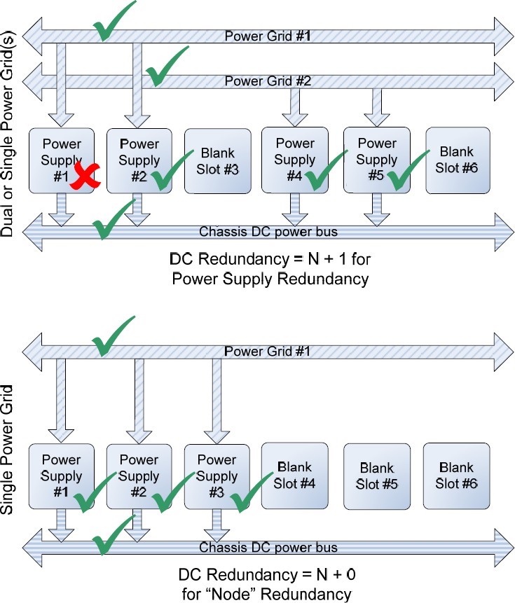
Figure 4 – DC Redundancy, 2 AC Grid or Single Grid
By default, the MX7000 is configured with no redundancy policy selected. If there is sufficient PSU capacity (i.e. extra PSUs above the capacity needed to operate the chassis), the system will continue to operate if there are any PSU failures. However, no fault will be raised.
Power Redundancy Policy Selection
Power Redundancy Policy selection can be changed via the MX7000 GUI. In the MX7000 web interface, click the Settings page. Then select the Redundancy Policy from the Redundancy Configuration section
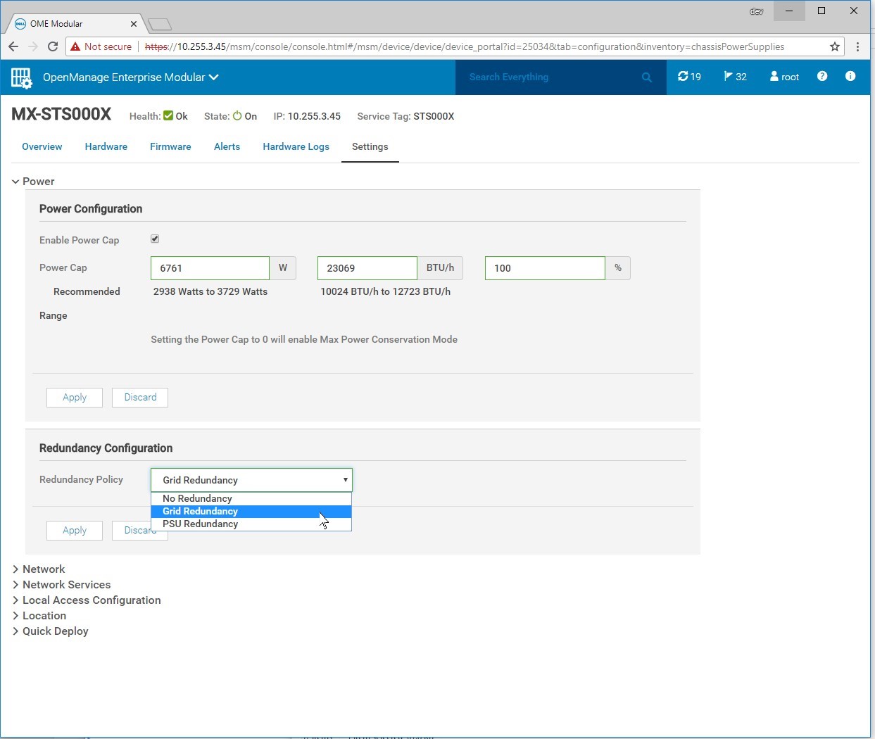
Figure 5 – Redundancy Configuration in the MX7000 Web Interface
Power Management
Shared power in modular systems take advantage of the power pool by distributing power without the waste seen in dedicated rack-mount servers and switchgear. The MX7000’s advanced power budget Inventory allows it to provide priority to powering infrastructure while guaranteeing computing resources can be used.
The Management Module and each server’s iDRAC management controller negotiates its required power, whether that be for simple power-on, AC recovery, or Wake-On-Lan. This inventory considers CPU, memory, storage, and other server I/O to provide additional margin should any power shortage occur.
Budgeting is transparent to the system administrator. The MX7000 automatically protects against using more power than is available by limiting which components can be powered on, as well as by dynamically limiting server power.
The MX7000 management module and the servers’ iDRAC modules work in concert to constantly monitor power conditions in the chassis. In the event of a power shortage, they will instantaneously limit power to servers, decreasing performance, but keeping the chassis online. Once the power shortage is corrected, servers will be allowed to return to their full performance.
Power Supply Fault Detection
The PowerEdge MX7000 logs failures of PSUs. Notifications will be sent per the configuration in the OpenManage Enterprise Modular web interface. The PSU utilizes four LEDs to help with issue identification: 3 on the front the PSU, one on the back:
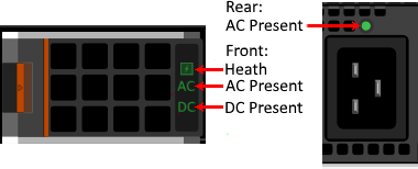
Figure 6 – PSU Fault LEDs in green
Front:
- Health – Green indicates the PSU is Healthy, Amber designates a fault
- AC Present – When illuminated, indicates that AC is detected and within tolerance.
- DC Present – When lit, shows that PSU is supplying DC to the chassis.
Rear:
AC Present – When illuminated, AC detected
Troubleshooting Tips:
- If the Rear AC Present LED fails to illuminate:
- Check to make sure the PSU in the front of the chassis is installed in the correct slot and is fully seated.
- Verify that the power cable is installed in an operating AC outlet/PDU
- If the Rear AC Present LED is illuminated but the Front AC Present LED is not:
- Verify that the AC power being provided by the utility is within tolerances.
- Check to make sure the PSU in the front of the chassis is installed in the correct slot and is fully seated.
- If the Health LED is Amber the PSU has a fault and needs to be cleared.
- Remove the PSU for a minimum of 30 seconds.
- Verify that nothing is obstructing the front outlet and the rear PSU pins are not damaged.
- Re-insert the PSU and verify that it is fully seated.
- If the Health LED blinks Amber multiple times and then turns off, PSU is indicating a capacity mismatch. Likely reasons for this are:
- PSU is connected to a different input voltage than the other PSUs (ex. 110 VAC instead of 208VAC).
- Input power power provided by the utility is not consistent or within tolerances.
- If the Health LED blinks Amber multiple times and then turns off, PSU is indicating a capacity mismatch. Likely reasons for this are:
- Re-insert the PSU and verify that it is fully seated.
Tolerances: 220VAC (single PSU runs 180V – 264VAC) or 110VAC input.
Related Blog Posts

Direct from Development – PowerEdge MX7000 At the Box Serial Access
Thu, 12 Nov 2020 19:26:21 -0000
|Read Time: 0 minutes
Summary
PowerEdge MX7000 comes with a Management Module that provides chassis management. This technical white paper describes the step by step “at- the-box” serial access feature of the chassis management firmware. A typical use of the serial access feature is for troubleshooting purpose when remote access to the management firmware is not available.
Preparation
What you need?
To prepare for serial access, you need the correct cable for connection. You will need a “micro-USB to USB” cable (Figure-1) long enough to connect your client system to the micro-USB port in the Management Module.
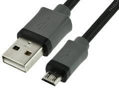
Figure 1 USB to Micro USB Cable
Where to connect?
The micro-USB port (Figure-2) for serial access is in the Management Module located at the rear of the chassis. If you see two Management Modules, look for the module that has the LED under “i” lit.
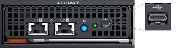
Figure 2 - Micro USB port to connect to
What you need in the client?
You can use any serial terminal client application of your choice, such as Tera Term or PuTTY.
Windows Client Host
If your client host system is running Windows, the default serial device driver should work. Open the Device Manager (type “devmgmt.msc” from command line) to determine which COM port Windows has created for your serial connection.
If Windows is not able to see the serial COM port or it is present but you are not able to connect, you may have to manually install the device driver. You can get this driver from a 3rd party vendor. Search for “cypress semiconductor usb serial driver download”. Look for the driver download link. After the manual driver installation, you should see the COM port for your connection (example in Figure-3).
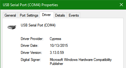
Figure 3 – 3rd party serial device driver in Windows
Linux Client Host
If your client host system is running Linux, the device driver to connect to the serial interface should already be installed. There is an extra step however that is required to correctly recognize the Management Module serial device.
The USB serial device is recognized by Linux as a “Thermometer” device and loads the cytherm kernel module. The following steps help to correctly recognize the Management Module serial device.
First, add this entry “blacklist cytherm” to the file “/etc/modprobe.d/blacklist.conf”. This will prevent loading the incorrect driver.
Next, connect the serial cable to the host system. If you have already connected the serial cable, you will need to unload the incorrect driver with the command “sudo rmmod cytherm”. Then re-connect the serial cable to the host system.
If you see “/dev/ttyACM0” then you are ready to connect. The “0” means it is the first serial device discovered.
Serial Console
Serial Console Menu
When a serial connection is established to the Management Module, the serial client application will be presented with the serial console’s main menu (Figure-4). It is populated with the available components to which serial connection can be made. On the upper right corner of the menu, it shows which Management Module you are connected to (the Active or the Standby). When you are finished, you may simply disconnect the cable and exit the serial client application.
The following sections describe each selection in the Main menu.
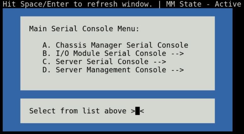
Figure 4 - Main menu
Chassis manager firmware console
Choosing option (A) from the Main menu takes you to the Chassis Manager firmware console. A serial session will open and a login prompt is displayed.
On successful login, you will have access to the Chassis Manager’s firmware racadm interface. To end the session, the exit sequence is “Ctrl-A Ctrl-X”. If using minicom in Linux, the exit sequence is “Ctrl-A Ctrl-A Ctrl-X”. Upon exit, you will see the Main menu.
I/O module firmware console
Choosing option (B) from the Main menu takes you to the I/O Module Console menu (Figure-5). The menu shows you the available I/O modules that support the serial interface.
Prior to selecting an I/O module, you will have the option to toggle the connection mode to either “binary” or non-binary” using option (B) from the menu. In “binary” mode, the terminal control characters from the client application are passed through the serial session.
Upon selection of an I/O module, a serial session will open and a login prompt is displayed. On successful login, you will have access to the I/O module firmware command line.
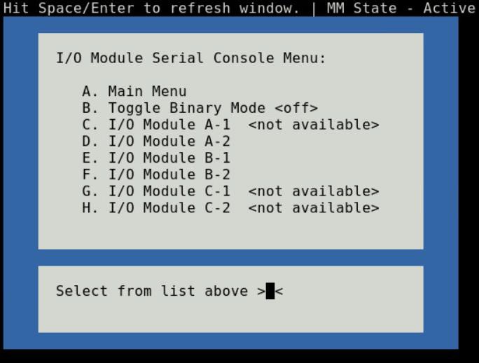
Figure 5 - I/O module console menu
To end a non-binary session, the exit sequence is “Ctrl-\”.
To end a binary session requires an extra step. The extra step is to login to the Chassis Manager’s web interface and go to Home > Troubleshoot > Terminate Serial Connection.
Server serial console
Choosing option (C) from the Main menu takes you to the Sled Host Serial Console menu (Figure-6). The menu shows you the available server host in a sled present in the chassis.
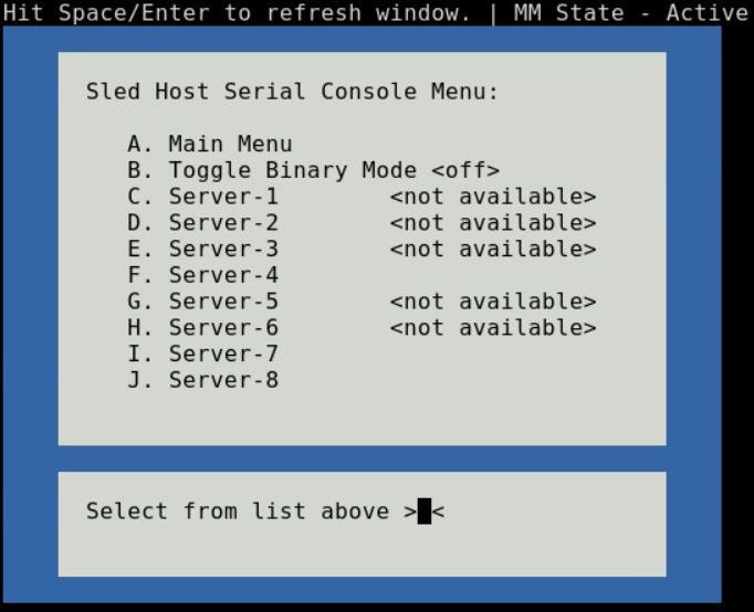
Figure 6 - Sled host serial menu
Prior to selecting a server sled, you will have the option to toggle the connection mode to either “binary” or non-binary” using option (B) from the menu. In “binary” mode, the terminal control characters from the client application are passed through the serial session.
Upon selection of a server sled, you will get access to the serial command line interface of the operating system running on the sled.
To end a non-binary session, the exit sequence is “Ctrl-\”. This exit sequence can be configured from the sled’s iDRAC UI.
To end a binary session requires an extra step. The extra step is to login to the Chassis Manager’s web interface and go to Home > Troubleshoot > Terminate Serial Connection.
Server management firmware console
Choosing option (D) from the Main menu takes you to the iDRAC Serial Console menu (Figure-7). The menu shows you the available iDRAC present in the chassis. iDRAC is the systems management firmware for a compute sled.
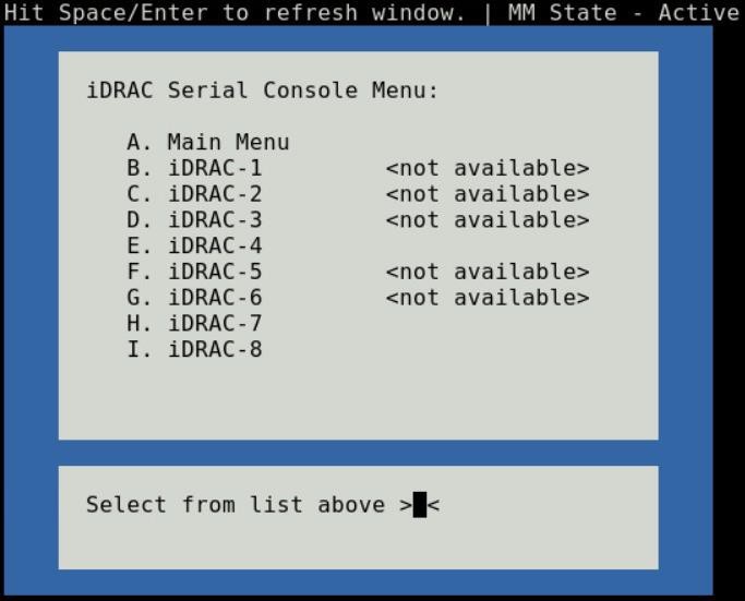
Figure 7- iDRAC console menu

Direct from Development – PowerEdge MX7000 LED Device Status
Thu, 12 Nov 2020 19:10:27 -0000
|Read Time: 0 minutes
Summary
The MX7000 chassis and modular devices in a MX7000 chassis are equipped with multi- purpose LEDs which can indicate the current health state of the device, provide identification or implement device specific features.
This whitepaper intends to provide a single point of comprehensive status information for LED behaviors on PowerEdge MX7000.
Users want to be able to look at the chassis and deduce its current health state when physically in front of the chassis. Most of the components that are present in the MX7000 chassis are able to display their current health state via LEDs.
Users also want to be able to accurately identify components in a chassis. A useful feature to do this is the Identify function that can be activated from the front panel, or remotely via the OpenManage Enterprise Modular GUI. This can be a very useful feature when you are managing a multi- chassis setup and want to remotely identify a particular device in the pool.
Some devices also implement their own specific LED behavior, for example PowerEdge MX5016s implement an LED feature that indicates mapping state. This document will cover these features.
Management Module LED Behavior
The Management Module (MM) is located at the rear of the chassis (Figure 1) and contains two LEDs: Power LED (Green only) and Status LED/Button (Blue or Amber).
Status LED/Button (Blue or Amber) is on the left and the Power LED (Green only) is on the right as shown by red highlights.
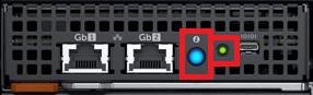
Figure 1: Management Module
The Power and Status LED (color is dependent on status) states are as follows:
Healthy Chassis
MM State | Power LED State | Status LED State |
Active | LED ON (Green) | LED ON (Blue-solid) |
Standby | LED ON (Green) | LED OFF |
Identify (Active) | LED ON (Green) | LED ON (Blue-blinking) |
Faulted Chassis
MM State | Power LED State | Status LED State |
Active | LED ON (Green) | LED ON (Amber-blinking) |
Identify (Active) | LED ON (Green) | LED ON (Blue-blinking) |
(Note: Only active MM will reflect faulted chassis state and provide identification functionality.)
Management Module Hardware Failure
Issue | Power LED State | Status LED State |
MM unable to power on | LED OFF | LED OFF |
MM unable to boot up | LED OFF | LED ON (Amber-solid) |
The Status LED/Button on the rear of the chassis changes to AMBER when any of the Front Panel iconic indicators shows AMBER. When the chassis/MM is in Identify State, the combo Status LED/Button shall always blink BLUE and override any other Status LED state.
IO Module LED Behavior
I/O Modules (IOMs) are inserted in the rear of the chassis and support a two-stacked arrangement of LEDS: Top = AMBER/GREEN, Bottom = BLUE.
Figure 2a – Typical Fab A/B IO Module: Power/Status LED on the top and Identification LED on bottom as shown by red highlights.

Figure 2b – Typical Fab C IO Module: Power/Status LED on the top and Identification LED on bottom as shown by red highlights.
The LEDs support the following functions:
IOM Health | Power/Status LED State | Identification LED State |
Healthy | LED ON (Green) | - |
Faulted | LED ON (Amber) | - |
Identify | - | LED ON (Blue-blinking) |
The green LED behavior can be overridden to indicate fabric mismatch. In case there is a fabric mismatch, green LED will blink for 2.5 seconds and then stay lit.
Sled LED Behavior
The Sleds are inserted in the front of the chassis and contain an LED for Power/Status/Identification via Blue or Amber colors.
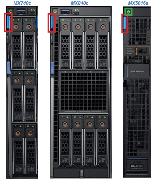
Figure 3: Current PowerEdge MX Sled Options
The Power/Status/Identification LED is on the top left highlighted in red.
The Power/Status/Identification (color is dependent on status) LED states for a sled device will be as follows:
Chassis manager firmware console
Sled Health | Power/Status/Identification LED State |
Off | LED_OFF |
Healthy | LED ON (Blue) |
Errors exist (System on/off) | LED ON (Amber-blinking) |
Identify | LED ON (Blue-blinking) |
Failsafe | LED ON (Amber-solid) |
For PowerEdge MX5016s (Figure 3), a cylindrical LED is also available marked with green highlight in the figure. Its behavior is as follows:
Mapping state | Cylinder LED on PowerEdge MX5016s |
Mapped to Compute that is powered ON | LED ON (Blinking) |
Unmapped | LED OFF |
All mapped compute sleds are off | LED OFF |
NOTE: It is unsafe to remove the PowerEdge MX5016s any time the LED is Blinking, as it is has active mappings to compute sleds that are powered on. To remove the PowerEdge MX5016s, either unmap storage from all compute sleds, or power down all compute sleds that are using this storage. See the User Guide for more information.
PSU LED Behavior
The Power Supply Units (PSUs) are inserted in the front of the chassis and utilize four LEDs: 3 on the front (figure below, left) and 1 in the back (figure below, right).

Figure 4 - Front and Rear PSU LEDs
The PSU LED states are as follows:
PSU State | Health LED (Front) | AC Present (Front) | DC Present (Front) | AC Present (Rear) |
Healthy | LED ON (Green) | LED ON | LED ON | LED ON |
Faulted | LED ON (Amber) | - | - | - |
On the front of the PSU, if the AC Present LED is illuminated, then AC is detected and within tolerance. If the DC Present LED is illuminated, then the PSU is supplying DC to the chassis. The AC Present LED on the rear of the chassis, when illuminated, indicates that AC is detected.
FAN LED Behavior
The Fans are inserted in the front and the back of the chassis (Figure 8) and contain one LED: Power/Status LED (Green or Amber).
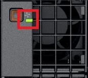
Figure 6 – Front Fans Power/Status LED
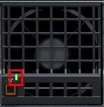
Figure 7 – Rear Fans Power/Status LED
The Power/Status/Identification (color is dependent on status) LED states will be as follows:
Fan Health | Power/Status LED State |
Off | LED_OFF |
Healthy | LED ON (Green) |
Fault | LED ON (Amber-blinking) |
Firmware Update in Progress | LED ON (Green-blinking) |
Conclusion: A thorough understanding of the physical LED status can ensure efficient health status and provide feedback for timely troubleshooting. The PowerEdge MX management module, compute sleds, storage sleds, IO Modules, power supply, and fans, each have LED state indicators that deliver identification on specific features.