


Deploying Tanzu Application Services on Dell EMC PowerFlex
Tue, 15 Dec 2020 14:35:58 -0000
|Read Time: 0 minutes
Introduction
Tanzu Application Service (TAS) architecture provides the best approach available today to enable agility at scale with the reliability that is must to address these challenges. PowerFlex family offers key value propositions of traditional and cloud-native production workloads, deployment flexibility, linear scalability, predictable high performance, and enterprise-grade resilience.
Tanzu Application Service (TAS)
The VMware Tanzu Application Service (TAS) is based on Cloud Foundry –an open-source cloud application platform that provides a choice of clouds, developer frameworks, and application services. Cloud Foundry is a multi-cloud platform for the deployment, management, and continuous delivery of applications, containers, and functions. TAS abstracts away the process of setting up and managing an application runtime environment so that developers can focus solely on their applications and associated data. Running a single command—cf push—creates a scalable environment for your application in seconds, which might otherwise take hours to spin up manually. TAS allows developers to deploy and deliver software quickly, without the need of managing the underlying infrastructure.
PowerFlex
PowerFlex (previously VxFlex OS) is the software foundation of PowerFlex software-defined storage. It is a unified compute, storage and networking solution delivering scale-out block storage service designed to deliver flexibility, elasticity, and simplicity with predictable high performance and resiliency at scale.
The PowerFlex platform is available in multiple consumption options to help customers meet their project and data center requirements. PowerFlex appliance and PowerFlex rack provide customers comprehensive IT Operations Management (ITOM) and life cycle management (LCM) of the entire infrastructure stack in addition to sophisticated high-performance, scalable, resilient storage services. PowerFlex appliance and PowerFlex rack are the two preferred and proactively marketed consumption options. PowerFlex is also available on VxFlex Ready Nodes for those customers interested in software-defined compliant hardware without the ITOM and LCM capabilities.
PowerFlex software-define storage with unified compute and networking offers flexibility of deployment architecture to help best meet the specific deployment and architectural requirements. PowerFlex can be deployed in a two-layer for asymmetrical scaling of compute and storage for “right-sizing capacities, single-layer (HCI), or in mixed architecture.
Deploying TAS on PowerFlex
For this example, a PowerFlex production cluster is set up using a Hyperconverged configuration. The production cluster has connectivity to the customer-data network and the private backend PowerFlex storage network. The PowerFlex production cluster consists of a minimum of four servers that host the workload and PowerFlex storage VMs. All the nodes are part of a single ESXi Cluster and part of the same PowerFlex Cluster. Each node contributes all their internal disk resources to PowerFlex cluster.
The PowerFlex management software manages the capacity of all of the disks and acts as a back-end for data access by presenting storage volumes to be consumed by the applications running on the nodes. PowerFlex Manager also provides the essential operational controls and lifecycle management tools. The production cluster hosts the compute nodes that are used for deployment of TAS VMs. TAS components are deployed across three dedicated compute clusters that are designated as three availability zones. These compute clusters are managed by the same 'compute workload' vCenter as the dedicated Edge cluster. The following figure depicts the layout in the lab environment:
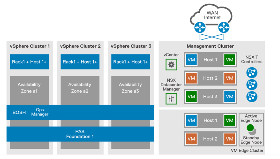
Figure 1. PowerFlex production cluster
The compute infrastructure illustrates the best practice architecture using 3 AZ’s using PowerFlex rack in hyperconverged configured nodes. This design ensures the high availability of nodes (i.e., nodes in AZ1 will still function if AZ2 or AZ3 goes down). A dedicated compute cluster in each AZ’s combines to form Isolation Zone (IZ). These AZ’s can be used to deploy and run the TAS stateful workloads requiring persistent storage. On the PowerFlex storage we have created volumes in the backend which are being mapped to vSphere as Datastores.
PowerFlex storage distributed data layout scheme is designed to maximize protection and optimize performance. A single volume is divided into chunks. These chunks will be distributed (striped) on physical disks throughout the cluster, in a balanced and random manner. Each chunk has a total of two copies for redundancy.
PowerFlex can be feature configured optionally to achieve additional data redundancy by enabling the feature Fault sets. Persistent Storage for each AZ could be its own PowerFlex cluster. By implementing PowerFlex feature Fault sets we can ensure that the persistent data availability all time. Fault Sets are subgroup of SDS s (Software defined Storage) installed on host servers within a Protection Domain. PowerFlex OS will mirror data for a Fault Set on SDSs that are outside the Fault Set. Thus, availability is assured even if all the servers within one Fault Set fail simultaneously.
PowerFlex enables flexible scale out capabilities for your data center also provides unparalleled elasticity and scalability. Start with a small environment for your proof of concept or a new application and add nodes as needed when requirements evolve.
The solution mentioned in this blog provides recommendations for deploying a highly available and production-ready Tanzu Application Service on Dell EMC PowerFlex rack infrastructure platform to meet the performance, scalability, resiliency, and availability requirements and describes its hardware and software components. For complete information, see Tanzu Application Services on PowerFlex rack - Solution Guide.
References
Related Blog Posts

Dell PowerFlex Bare Metal with Amazon Elastic Kubernetes Service Anywhere, and We Do Mean “Anywhere!”

Mon, 18 Jul 2022 15:52:39 -0000
|Read Time: 0 minutes
Anywhere, that’s a powerful statement, especially to someone who works in IT. That could be in a cloud, or in a set of virtual machines in your data center, or even physical hosts. What if you could run Amazon Elastic Kubernetes Service (EKS) Anywhere on a virtual machine or on bare-metal, anywhere, including your data center?
You might have read my previous blog where we discussed running Amazon EKS Anywhere on Dell PowerFlex in a virtual environment. This time we are going further and have validated Amazon EKS Anywhere on a bare-metal instance of PowerFlex.
The good old days
If you are old enough to remember, like I am, the days before virtualization, with stranded resources and data centers with enormous footprints to support all the discrete servers and siloed workloads, you might be curious: Why would anyone go back to bare-metal?
Having been part of the movement all the way back to 2006, it’s a good question. In simple terms, what we are seeing today is not a return to the bare-metal siloed data centers of 20 years ago. Instead, we are seeing an improved utilization of resources by leveraging micro services, be that in the cloud, in virtualized environments, or with bare-metal. In addition, it provides greater portability and scalability than could ever have been imagined 20 years ago. This is thanks to the use of containers and the way they isolate processes from each other. Additionally, with a bare-metal platform running containers, more system resources can be directed to workloads than if the containers were nested inside of a virtual environment.
This is central to the concept of a DevOps-ready platform. In the coming weeks, we will expand on how this enhances the productivity of native cloud operations for today’s modern businesses. You will find this on the Dell Digital blog with the title Customer Choice Comes First: Dell Technologies and AWS EKS Anywhere.
Beyond just the economics of this, there are scenarios where a bare-metal deployment can be helpful. This includes low latency and latency sensitive applications that need to run near the data origin. This of course can include edge scenarios where it is not practical to transmit vast quantities of data.
Data sovereignty and compliance can also be addressed as an Amazon EKS Anywhere solution. While data and associated processing can be done in the data center, to maintain compliance requirements, it can still be part of a holistic environment that is displayed in the Amazon EKS Console when the Amazon EKS Connector has been configured. This allows for monitoring of applications running anywhere in the environment.
Digging deeper
Digging deeper on this concept, PowerFlex is a software defined infrastructure (SDI) that provides a powerful tool in delivering the modern bare-metal or virtualized options that best suit application deployment needs. The hardware infrastructure becomes malleable to the needs of the data center and can take on various forms of modern infrastructure, from hyper-converged to bare-metal. This has always been a core tenet of PowerFlex.
When Amazon EKS Anywhere is deployed on PowerFlex, it becomes possible to optimize the IT environment precisely for the needs of the environment, instead of forcing it to conform to the limits of IT infrastructure. Bare-metal hosts can provide microservices for large applications, such as databases and websites, where a container instance may be created and destroyed rapidly and on a massive scale.
The architecture
Let’s look at the Amazon EKS Anywhere validated architecture in the following figure. It shows how PowerFlex delivers a unique software-defined 3-tier architecture that can asymmetrically scale compute separate from storage.
The bottom portion of the figure consists of PowerFlex – storage-only nodes (1U). In the middle of the diagram are the hosts used for the control plane and worker nodes. These are PowerFlex – compute-only nodes (2U). On the far left are the admin and Tinkerbell nodes that allow for administration of the environment. Lastly, in the top set of boxes, we have the control plane, at the top left, that provides operational control and orchestration. The worker nodes, at the top right, handle the workloads.
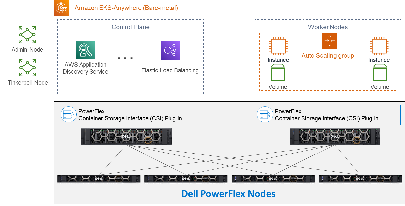
Let’s look at some important aspects of each area shown here, starting with the storage nodes. Each storage node contains five 1.4TB SAS SSD drives and eight 25GbE network links. For the validation, as shown here, four PowerFlex storage nodes were used to provide full redundancy.
For the compute nodes, we used two 2U nodes. These two hosts have the PowerFlex Container Storage Interface (CSI) Plug-in installed to provide access to the PowerFlex storage. This is deployed as part of the PXE boot process along with the Ubuntu OS. It’s important to note that there is no hypervisor installed and that the storage is provided by the four storage nodes. This creates a two-layer architecture which, as you can see, creates separate storage and compute layers for the environment.
Using a two-layer architecture makes it possible to scale resources independently as needed in the environment, which allows for optimal resource utilization. Thus, if more storage is needed, it can be scaled without increasing the amount of compute. And likewise, if the environment needs additional compute capacity, it can easily be added.
Cluster Creation
Outside of the Amazon EKS Anywhere instance are two nodes. Both are central to building the control plane and worker nodes. The admin node is where the user can control the Amazon EKS Anywhere instance and serves as a portal to upload inventory information to the Tinkerbell node. The Tinkerbell node serves as the infrastructure services stack and is key in the provisioning and PXE booting of the bare-metal workloads.
When a configuration file with the data center hardware has been uploaded, Tinkerbell generates a cluster configuration file. The hardware configuration and cluster configuration files, both in YAML format, are processed by Tinkerbell to create a boot strap kind cluster on the admin host to install the Cluster-API (CAPI) and the Cluster-API-Provider-Tinkerbell (CAPT).
With the base control environment operational, CAPI creates cluster node resources, and CAPT maps and powers on the corresponding bare-mental servers. The bare-metal servers PXE boot from the Tinkerbell node. The bare-metal servers then join the Kubernetes cluster. Cluster management resources are transferred from the bootstrap cluster to the target Amazon EKS Anywhere workload cluster. The local bootstrap kind cluster is then deleted from the admin machine. This creates both the Control Plane and Worker Nodes. With the cluster established, SDC drivers are installed on the Worker node(s) along with the Dell CSI Plug-in for PowerFlex. At this point, workloads can be deployed to the Worker node(s) as needed.
Cluster Provisioning
With the infrastructure deployed, our solutions engineers were able to test the Amazon EKS Anywhere environment. The testing included provisioning persistent volume claims (PVCs), expanding PVCs, and snapshotting them. All of this functionality relies on the Dell CSI Plugin for PowerFlex. Following this validation, a test workload can be deployed on the bare-metal Amazon EKS Anywhere environment.
If you would like to explore the deployment further, the Dell Solutions Engineering team is creating a white paper on the deployment of Amazon EKS Anywhere that covers these details in greater depth. When published, we will be sure to update this blog with a link to the white paper.
Anywhere
This validation enables the use of Amazon EKS Anywhere across bare-metal environments, expanding the use beyond the previous validation of virtual environments. This means that you can use Amazon EKS Anywhere anywhere, really!
With bare-metal deployments, it is possible to scale environments independently based on resource demands. PowerFlex software defined infrastructure not only supports a malleable environment like this, but also allows mixing environments to include hyper converged components. This means that an infrastructure can be tailored to the environment’s needs — instead of the environment being forced to conform to the infrastructure. It also creates an environment that unifies the competing demands of data sovereignty and cloud IT, by enabling data to maintain appropriate residence while unifying the control plane.
If you’re interested in finding out more about how you can leverage Amazon EKS Anywhere in your bare-metal PowerFlex environment, reach out to your Dell representative. Where is anywhere for you?
Resources
- Deploying a test workload
- Amazon Elastic Kubernetes Service Anywhere on Dell PowerFlex
- Introducing bare metal deployments for Amazon EKS Anywhere
- Blog: Customer Choice Comes First: Dell Technologies and AWS EKS Anywhere
Authors: Tony Foster
Twitter: @wonder_nerd
LinkedIn
Syed Abrar LinkedIn

Q1 2024 Update for Terraform Integrations with Dell Infrastructure

Tue, 02 Apr 2024 14:45:56 -0000
|Read Time: 0 minutes
This post covers all the new Terraform resources and data sources that have been released in the last two quarters: Q4’23 and Q1 ‘24. You can check out previous releases of Terraform providers here: Q1-2023, Q2-2023, and Q3-2023. I also covered the first release of PowerScale provider here.
Here is a summary of the Dell Terraform Provider versions released over the last two quarters:
- v1.1 and v1.2 of the provider for PowerScale
- v1.3 and v1.4 of the provider for PowerFlex
- v1.3 and v1.4 of the provider for PowerStore
- v1.2 of the Provider for OME
- v1.1 and v1.2 of the Provider for Redfish
PowerScale Provider v1.1 and v1.2
PowerScale received the most number of new Terraform capabilities in the last few months. New resources and corresponding data sources have been under the following workflow categories:
- Data Management
- User and Access Management
- Cluster Management
Data management
Following is the summary for the different resource-datasource pairs introduced to automate operations related to Data management on PowerScale:
Snapshots: CRUD operations for Snapshots
Here's an example of how to create a snapshot resource within a PowerScale storage environment using Terraform:
resource "powerscale_snapshot" "example_snapshot" {
  name        = "example-snapshot"
  filesystem  = powerscale_filesystem.example_fs.id
  description = "Example snapshot description"
  // Add any additional configurations as needed
}- name: Specifies the name of the snapshot to be created.
- filesystem: References the PowerScale filesystem for which the snapshot will be created.
- description: Provides a description for the snapshot.
Here's an example of how to retrieve information about existing snapshots within a PowerScale environment using Terraform:
data "powerscale_snapshot" "existing_snapshot" {
  name = "existing-snapshot"
}

output "snapshot_id" {
  value = data.powerscale_snapshot.existing_snapshot.id
}- name: Specifies the name of the existing snapshot to query.
Snapshot schedules: CRUD operations for Snapshot schedules
Following is an example of how to define a snapshot schedule resource:
resource "powerscale_snapshot_schedule" "example_schedule" {
  name                = "example-schedule"
  filesystem          = powerscale_filesystem.example_fs.id
  snapshot_type       = "weekly"
  retention_policy    = "4 weeks"
  snapshot_start_time = "23:00"
  // Add any additional configurations as needed
}- name: Specifies the name of the snapshot schedule.
- filesystem: References the PowerScale filesystem for which the snapshot schedule will be applied.
- snapshot_type: Specifies the type of snapshot schedule, such as "daily", "weekly", and so on.
- retention_policy: Defines the retention policy for the snapshots created by the schedule.
- snapshot_start_time: Specifies the time at which the snapshot creation process should begin.
Data Source Example:
The following example shows how to retrieve information about existing snapshot schedules within a PowerScale environment using Terraform. The powerscale_snapshot_schedule data source fetches information about the specified snapshot schedule. An output is defined to display the ID of the retrieved snapshot schedule:
data "powerscale_snapshot_schedule" "existing_schedule" {
  name = "existing-schedule"
}

output "schedule_id" {
  value = data.powerscale_snapshot_schedule.existing_schedule.id
}- name: Specifies the name of the existing snapshot schedule to query.
File Pool Policies: CRUD operations for File Pool Policies
File policies in PowerScale help establish policy-based workflows like file placement and tiering of files that match certain criteria. Following is an example of how the new file pool policy resource can be configured:
resource "powerscale_filepool_policy" "example_filepool_policy" {
  name = "filePoolPolicySample"
  is_default_policy = false

  file_matching_pattern = {
    or_criteria = [
      {
        and_criteria = [

          {
            operator = ">"
            type     = "size"
            units    = "B"
            value    = "1073741824"
          },
          {
            operator          = ">"
            type              = "birth_time"
             use_relative_time = true
            value             = "20"
          },
          {
            operator          = ">"
            type              = "metadata_changed_time"
             use_relative_time = false
            value             = "1704742200"
          },
          {
            operator          = "<"
            type              = "accessed_time"
             use_relative_time = true
            value             = "20"
          }
        ]
      },
      {
        and_criteria = [
          {
            operator          = "<"
            type              = "changed_time"
             use_relative_time = false
            value             = "1704820500"
          },
          {
             attribute_exists = false
            field            = "test"
            type             = "custom_attribute"
            value            = ""
          },
          {
            operator = "!="
            type     = "file_type"
            value    = "directory"
          },
          {
             begins_with    = false
            case_sensitive = true
            operator       = "!="
            type           = "path"
            value          = "test"
          },
          {
            case_sensitive = true
            operator       = "!="
            type           = "name"
            value          = "test"
          }
        ]
      }
    ]
  }
  # A list of actions to be taken for matching files. (Update Supported)
  actions = [

    {
       data_access_pattern_action = "concurrency"
      action_type                = "set_data_access_pattern"
    },
    {
       data_storage_policy_action = {
        ssd_strategy = "metadata"
        storagepool  = "anywhere"
      }
      action_type = "apply_data_storage_policy"
    },
    {
       snapshot_storage_policy_action = {
        ssd_strategy = "metadata"
        storagepool  = "anywhere"
      }
      action_type = "apply_snapshot_storage_policy"
    },
    {
       requested_protection_action = "default"
      action_type                 = "set_requested_protection"
    },
    {
       enable_coalescer_action = true
      action_type             = "enable_coalescer"
    },
    {
      enable_packing_action = true,
      action_type           = "enable_packing"
    },
    {
      action_type = "set_cloudpool_policy"
       cloudpool_policy_action = {
         archive_snapshot_files = true
        cache = {
          expiration = 86400
          read_ahead = "partial"
          type       = "cached"
        }
        compression                  = true
        data_retention               = 604800
        encryption                   = true
         full_backup_retention        = 145152000
         incremental_backup_retention = 145152000
        pool                         = "cloudPool_policy"
         writeback_frequency          = 32400
      }
    }
  ]

  description = "filePoolPolicySample description"

  apply_order = 1
}
You can import existing file pool policies using the file pool policy ID:
terraform import powerscale_filepool_policy.example_filepool_policy <policyID>
or by simply referencing the default policy:
terraform import powerscale_filepool_policy.example_filepool_policy is_default_policy=true
The data source can be used to get a handle to a particular file pool policy:
data "powerscale_filepool_policy" "example_filepool_policy" {
  filter {
    # Optional list of names to filter upon
    names = ["filePoolPolicySample", "Default policy"]
  }
}
or to get the complete list of policies including the default policy:
data "powerscale_filepool_policy" "all" {
}
You can then deference into the data structure as needed.
User and Access management
Following is a summary of the different resource-datasource pairs introduced to automate operations related to User and Access management on PowerScale:
LDAP Providers: CRUD operations
To create and manage LDAP providers, you can use the new resource as follows:
resource "powerscale_ldap_provider" "example_ldap_provider" {
  # Required params for creating and updating.
  name = "ldap_provider_test"
  # root of the tree in which to search identities.
  base_dn = "dc=tthe,dc=testLdap,dc=com"
  # Specifies the server URIs. Begin URIs with ldap:// or ldaps://
  server_uris = ["ldap://10.225.108.54"]
}
You can import existing LDAP providers using the provider name:
terraform import powerscale_ldap_provider.example_ldap_provider <ldapProviderName>
and also get a handle using the corresponding data source using a variety of criteria:
data "powerscale_ldap_provider" "example_ldap_provider" {
  filter {
    names = ["ldap_provider_name"]
    # If specified as "effective" or not specified, all fields are returned. If specified as "user", only fields with non-default values are shown. If specified as "default", the original values are returned.
    scope = "effective"
  }
}
ACL Settings: CRUD operations
PowerScale OneFS provides very powerful ACL capabilities, including a single namespace for multi-protocol access and its own internal ACL representation to perform access control. The internal ACL is presented as protocol-specific views of permissions so that NFS exports display POSIX mode bits for NFSv3 and shows ACL for NFSv4 and SMB. Now, we have a new resource to manage the global ACL settings for a given cluster:
resource "powerscale_aclsettings" "example_acl_settings" {
  # Optional fields both for creating and updating
  # Please check the acceptable inputs for each setting in the documentation
  #     access                  = "windows"
  #     calcmode                = "approx"
  #     calcmode_group          = "group_aces"
  #     calcmode_owner          = "owner_aces"
  #     calcmode_traverse       = "ignore"
  #     chmod                   = "merge"
  #     chmod_007               = "default"
  #     chmod_inheritable       = "no"
  #     chown                   = "owner_group_and_acl"
  #     create_over_smb         = "allow"
  #     dos_attr                = "deny_smb"
  #     group_owner_inheritance = "creator"
  #     rwx                     = "retain"
  #     synthetic_denies        = "remove"
  #     utimes                  = "only_owner"
}
Import is supported, and there is corresponding data source for the resource as well.
Smart Quotas: CRUD operations
Following is an example that shows how to define a quota resource:
resource "powerscale_quota" "example_quota" {
  name         = "example-quota"
  filesystem   = powerscale_filesystem.example_fs.id
  size         = "10GB"
  soft_limit   = "8GB"
  hard_limit   = "12GB"
  grace_period = "7d"
  // Add any additional configurations as needed
}- name: Specifies the name of the quota.
- filesystem: References the PowerScale filesystem to associate with the quota.
- size: Sets the size of the quota.
- soft_limit: Defines the soft limit for the quota.
- hard_limit: Defines the hard limit for the quota.
- grace_period: Specifies the grace period for the quota.
Data Source Example:
The following code snippet illustrates how to retrieve information about existing smart quotas within a PowerScale environment using Terraform. The powerscale_quota data source fetches information about the specified quota. An output is defined to display the ID of the retrieved quota:
data "powerscale_quota" "existing_quota" {
  name = "existing-quota"
}

output "quota_id" {
  value = data.powerscale_quota.existing_quota.id
}- name: Specifies the name of the existing smart quota to query.
Cluster management
Groupnet: CRUD operations
Following is an example that shows how to define a GroupNet resource:
resource "powerscale_groupnet" "example_groupnet" {
  name       = "example-groupnet"
  subnet     = powerscale_subnet.example_subnet.id
  gateway    = "192.168.1.1"
  netmask    = "255.255.255.0"
  vlan_id    = 100
  // Add any additional configurations as needed
}- name: Specifies the name of the GroupNet.
- subnet: References the PowerScale subnet to associate with the GroupNet.
- gateway: Specifies the gateway for the GroupNet.
- netmask: Defines the netmask for the GroupNet.
- vlan_id: Specifies the VLAN ID for the GroupNet.
Data Source Example:
The following code snippet illustrates how to retrieve information about existing GroupNets within a PowerScale environment using Terraform. The powerscale_groupnet data source fetches information about the specified GroupNet. An output is defined to display the ID of the retrieved GroupNet:
data "powerscale_groupnet" "existing_groupnet" {
  name = "existing-groupnet"
}

output "groupnet_id" {
  value = data.powerscale_groupnet.existing_groupnet.id
}- name: Specifies the name of the existing GroupNet to query.
Subnet: CRUD operations
Resource Example:
The following code snippet shows how to provision a new subnet:
resource "powerscale_subnet" "example_subnet" {
  name         = "example-subnet"
  ip_range     = "192.168.1.0/24"
  network_mask = 24
  gateway      = "192.168.1.1"
  dns_servers  = ["8.8.8.8", "8.8.4.4"]
  // Add any additional configurations as needed
}- name: Specifies the name of the subnet to be created.
- ip_range: Defines the IP range for the subnet.
- network_mask: Specifies the network mask for the subnet.
- gateway: Specifies the gateway for the subnet.
- dns_servers: Lists the DNS servers associated with the subnet.
Data Source Example:
The powerscale_subnet data source fetches information about the specified subnet. The following code snippet illustrates how to retrieve information about existing subnets within a PowerScale environment. An output block is defined to display the ID of the retrieved subnet:
data "powerscale_subnet" "existing_subnet" {
  name = "existing-subnet"
}

output "subnet_id" {
  value = data.powerscale_subnet.existing_subnet.id
}- name: Specifies the name of the existing subnet to query. The result is stored in the data object called existing_subnet.
Network pool
Following is an example demonstrating how to define a network pool resource:
resource "powerscale_networkpool" "example_network_pool" {
  name       = "example-network-pool"
  subnet     = powerscale_subnet.example_subnet.id
  gateway    = "192.168.1.1"
  netmask    = "255.255.255.0"
  start_addr = "192.168.1.100"
  end_addr   = "192.168.1.200"
  // Add any additional configurations as needed
}- name: Specifies the name of the network pool.
- subnet: References the PowerScale subnet to associate with the network pool.
- gateway: Specifies the gateway for the network pool.
- netmask: Defines the netmask for the network pool.
- start_addr and end_addr: Specify the starting and ending IP addresses for the network pool range.
Data Source Example:
The following code snippet illustrates how to retrieve information about existing network pools. The powerscale_networkpool data source fetches information about the specified network pool. An output is defined to display the ID of the retrieved network pool:
data "powerscale_networkpool" "existing_network_pool" {
  name = "existing-network-pool"
}

output "network_pool_id" {
  value = data.powerscale_networkpool.existing_network_pool.id
}- name: Specifies the name of the existing network pool to query.
SmartPool settings
Here's an example that shows how to configure SmartPool settings within a PowerScale storage environment using Terraform:
resource "powerscale_smartpool_settings" "example_smartpool_settings" {
  name                    = "example-smartpool-settings"
  default_policy          = "balanced"
  compression             = true
  deduplication           = true
  auto_tiering            = true
  auto_tiering_policy     = "performance"
   auto_tiering_frequency  = "weekly"
  // Add any additional configurations as needed
}- name: Specifies the name of the SmartPool settings.
- default_policy: Sets the default policy for SmartPool.
- compression: Enables or disables compression.
- deduplication: Enables or disables deduplication.
- auto_tiering: Enables or disables auto-tiering.
- auto_tiering_policy: Sets the policy for auto-tiering.
- auto_tiering_frequency: Sets the frequency for auto-tiering.
Data Source Example:
The following example shows how to retrieve information about existing SmartPool settings within a PowerScale environment using Terraform. The powerscale_smartpool_settings data source fetches information about the specified SmartPool settings. An output is defined to display the ID of the retrieved SmartPool settings:
data “powerscale_smartpool_settings” “existing_smartpool_settings” {
  name = “existing-smartpool-settings”
}

output “smartpool_settings_id” {
  value = data.powerscale_smartpool_settings.existing_smartpool_settings.id
}- name: Specifies the name of the existing SmartPool settings to query.
New resources
New resources and datasources are also available for the following entities:
- NTP Server
- NTP Settings
- Cluster Email Settings
In addition to the previously mentioned resource-datasource pairs for PowerScale Networking, an option to enable or disable “Source based networking” has been added to the Network settings resource. The corresponding datasources can retrieve this setting on a PowerScale cluster.
PowerFlex Provider v1.3 and v1.4
The following new resources and corresponding datasources have been added to PowerFlex:
Fault Sets: CRUD and Import operations
The following is an example that shows how to define a Fault Set resource within a PowerFlex storage environment using Terraform:
resource "powerflex_fault_set" "example_fault_set" {
  name           = "example-fault-set"
  protection_domain_id = powerflex_protection_domain.example_pd.id
  fault_set_type = "RAID-1"
  // Add any additional configurations as needed
}- name: Specifies the name of the Fault Set.
- protection_domain_id: References the PowerFlex Protection Domain to associate with the Fault Set.
- fault_set_type: Defines the type of Fault Set, such as "RAID-1".
If you would like to bring an existing fault set resource into Terraform state management, you can import it using the fault set id:
terraform import powerflex_fault_set.fs_import_by_id "<id>"
Data Source Example:
The following code snippet illustrates how to retrieve information about existing Fault Sets within a PowerFlex environment using Terraform. The powerflex_fault_set data source fetches information about the specified Fault Set. An output is defined to display the ID of the retrieved Fault Set:
Ldata "powerflex_fault_set" "existing_fault_set" {
  name = "existing-fault-set"
}

output "fault_set_id" {
  value = data.powerflex_fault_set.existing_fault_set.id
}- name: Specifies the name of the existing Fault Set to query.
Snapshot policies: CRUD operations
- Snapshot policy resource – create, update, and delete.
- Snapshot policy data source – to get information of an existing policy.
Two new data sources
- powerflex_node: to get complete information related to a PowerFlex node firmware, hardware, and node health details.
- powerflex_template: this is a massive object that has information categorized into multiple groups within this object.
OME Provider v1.2
Following are the new resources to support Firmware baselining and compliance that have been added to the Dell OME Provider:
- Firmware Catalog
- Firmware Baselines
Firmware Catalog
Here is an example of how the catalog resource can be used to create or update catalogs:
# Resource to manage a new firmware catalog
resource "ome_firmware_catalog" "firmware_catalog_example" {
  # Name of the catalog required
  name = "example_catalog_1"

  # Catalog Update Type required.
  # Sets to Manual or Automatic on schedule catalog updates of the catalog.
  # Defaults to manual.
  catalog_update_type = "Automatic"

  # Share type required.
  # Sets the different types of shares (DELL_ONLINE, NFS, CIFS, HTTP, HTTPS)
  # Defaults to DELL_ONLINE
  share_type = "HTTPS"

  # Catalog file path, required for share types (NFS, CIFS, HTTP, HTTPS)
  # Start directory path without leading '/' and use alphanumeric characters.
  catalog_file_path = "catalogs/example_catalog_1.xml"

  # Share Address required for share types (NFS, CIFS, HTTP, HTTPS)
  # Must be a valid ipv4 (x.x.x.x), ipv6(xxxx:xxxx:xxxx:xxxx:xxxx:xxxx:xxxx:xxxx), or fqdn(example.com)
  # And include the protocol prefix ie (https://)
  share_address = "https://1.2.2.1"

  # Catalog refresh schedule, Required for catalog_update_type Automatic.
  # Sets the frequency of the catalog refresh.
  # Will be ignored if catalog_update_type is set to manual.
  catalog_refresh_schedule = {
    # Sets to (Weekly or Daily)
    cadence = "Weekly"
    # Sets the day of the week (Monday, Tuesday, Wednesday, Thursday, Friday, Saturday, Sunday)
    day_of_the_week = "Wednesday"
    # Sets the hour of the day (1-12)
    time_of_day = "6"
    # Sets (AM or PM)
    am_pm = "PM"
  }

  # Domain optional value for the share (CIFS), for other share types this will be ignored
  domain = "example"

  # Share user required value for the share (CIFS), optional value for the share (HTTPS)
  share_user = "example-user"

  # Share password required value for the share (CIFS), optional value for the share (HTTPS)
  share_password = "example-pass"
}
Existing catalogs can be imported into the Terraform state with the import command:
# terraform import ome_firmware_catalog.cat_1 <id>
terraform import ome_firmware_catalog.cat_1 1
After running the import command, populate the name field in the config file to start managing this resource.
Firmware Baseline
Here is an example that shows how a baseline can be compared to an array of individual devices or device groups:
# Resource to manage a new firmware baseline
resource "ome_firmware_baseline" "firmware_baseline" {
  // Required Fields
  # Name of the catalog
  catalog_name = "tfacc_catalog_dell_online_1"
  # Name of the Baseline
  name = "baselinetest"

  // Only one of the following fields (device_names, group_names , device_service_tags) is required
  # List of the Device names to associate with the firmware baseline.
  device_names = ["10.2.2.1"]

  # List of the Group names to associate with the firmware baseline.
  # group_names = ["HCI Appliances","Hyper-V Servers"]

  # List of the Device service tags to associate with the firmware baseline.
  # device_service_tags = ["HRPB0M3"]

  // Optional Fields
  // This must always be set to true. The size of the DUP files used is 64 bits."
  #is_64_bit = true

  // Filters applicable updates where no reboot is required during create baseline for firmware updates. This field is set to false by default.
   #filter_no_reboot_required = true

  # Description of the firmware baseline
  description = "test baseline"
}
Although the resource supports terraform import, in most cases a new baseline can be created using a Firmware catalog entry.
Following is a list of new data sources and supported operations in Terraform Provider for Dell OME:
- Firmware Repository
- Firmware Baseline Compliance Report
- Firmware Catalog
- Device Compliance Report
RedFish Provider v1.1 and 1.2
Several new resources have been added to the Redfish provider to access and set different iDRAC attribute sets. Following are the details:
Certificate Resource
This is a resource for the import of the ssl certificate to iDRAC based on the input parameter Type. After importing the certificate, the iDRAC will automatically restart. By default, iDRAC comes with a self-signed certificate for its web server. If the user wants to replace with his/her own server certificate (signed by Trusted CA), two kinds of SSL certificates are supported: (1) Server certificate and (2) Custom certificate. Following are the steps to generate these certificates:
- Server Certificate:
- Generate the CSR from iDRAC.
- Create the certificate using CSR and sign with trusted CA.
- The certificate should be signed with hashing algorithm equivalent to sha256
- Custom Certificate:
- An externally created custom certificate which can be imported into the iDRAC.
- Convert the external custom certificate into PKCS#12 format, and it should be encoded via base64. The conversion requires passphrase which should be provided in 'passphrase' attribute.
Boot Order Resource
This Terraform resource is used to configure Boot Order and enable/disable Boot Options of the iDRAC Server. We can read the existing configurations or modify them using this resource.
Boot Source Override Resource
This Terraform resource is used to configure Boot sources of the iDRAC Server. If the state in boot_source_override_enabled is set once or continuous, the value is reset to disabled after the boot_source_override_target actions have completed successfully. Changes to these options do not alter the BIOS persistent boot order configuration.
Manager Reset
This resource is used to reset the manager.
Lifecycle Controller Attributes Resource
This Terraform resource is used to get and set the attributes of the iDRAC Lifecycle Controller.
System Attributes Resource
This Terraform resource is used to configure System Attributes of the iDRAC Server. We can read the existing configurations or modify them using this resource. Import is also supported for this resource to include existing System Attributes in Terraform state.
iDRAC Firmware Update Resource
This Terraform resource is used to update the firmware of the iDRAC Server based on a catalog entry.
Resources
Here are the link sets for key resources for each of the Dell Terraform providers:
- Provider for PowerScale
- Provider for PowerFlex
- Provider for PowerStore
- Provider for Redfish
Author: Parasar Kodati, Engineering Technologist, Dell ISG