


Deploying Microsoft SQL Server Big Data Clusters on OpenShift platform using PowerFlex

Introduction
Microsoft SQL Server 2019 introduced a groundbreaking data platform with SQL Server 2019 Big Data Clusters (BDC). SQL Server BDC are designed to solve the big data challenge faced by most organizations today. You can use SQL Server BDC to organize and analyze large volumes of data, you can also combine high value relational data with big data. In this blog, I will describe the deployment of Microsoft SQL Server BDC on an OpenShift container platform using Dell EMC PowerFlex software-defined storage.
PowerFlex
PowerFlex (previously VxFlex OS) is the software foundation of PowerFlex software-defined storage. It is a unified compute storage and networking solution delivering scale-out block storage service designed to deliver flexibility, elasticity, and simplicity with predictable high performance and resiliency at scale.
The PowerFlex platform is available in multiple consumption options to help customers meet their project and data center requirements. PowerFlex appliance and PowerFlex rack provide customers comprehensive IT Operations Management (ITOM) and life cycle management (LCM) of the entire infrastructure stack in addition to sophisticated high-performance, scalable, resilient storage services. PowerFlex appliance and PowerFlex rack are the two preferred and proactively marketed consumption options. PowerFlex is also available on VxFlex Ready Nodes for those customers interested in software-defined compliant hardware without the ITOM and LCM capabilities.
PowerFlex software-define storage with unified compute and networking offers flexibility of deployment architecture to help best meet the specific deployment and architectural requirements. PowerFlex can be deployed in a two-layer for asymmetrical scaling of compute and storage for “right-sizing capacities, single-layer (HCI), or in mixed architecture.
OpenShift Container Platform
Red Hat® OpenShift® Container Platform is a platform to deploy and create containerized applications. OpenShift Container Platform provides administrators and developers with the tools they require to deploy and manage applications and services at scale. OpenShift Container Platform offers enterprises full control over their Kubernetes environments, whether they are on-premises or in the public cloud, giving you the freedom to build and run applications anywhere.
Microsoft SQL Server Big Data Clusters Overview
Microsoft SQL Server Big Data Clusters are designed to address big data challenges in a unique way, BDC solves many traditional challenges faced in building big-data and data-lake environments. You can query external data sources, store big data in HDFS managed by SQL Server, or query data from multiple external data sources using the cluster. See an overview of Microsoft SQL Server 2019 Big Data Clusters on the Microsoft page Microsoft SQL Server BDC details and on the GitHub page SQL Server BDC Workshops.
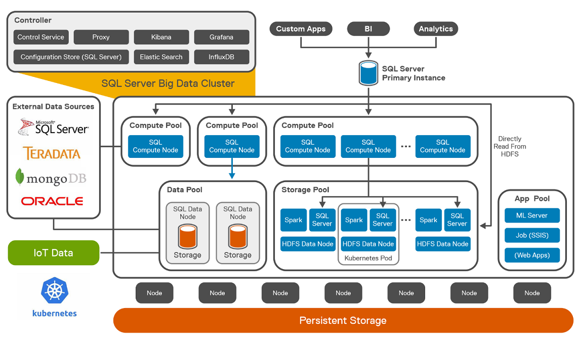 SQL Server Big Data Cluster components
Deploying OpenShift Container Platform on PowerFlex
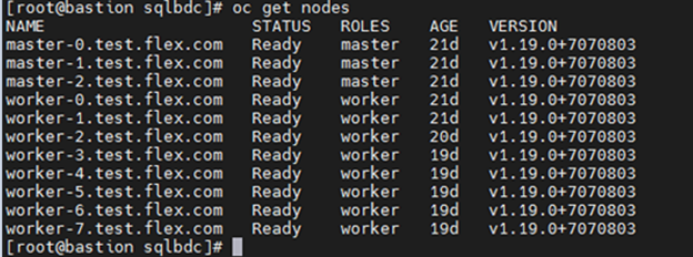
The OpenShift cluster is configured with three master nodes and eight worker nodes. To install OpenShift Container Platform on PowerFlex, see OpenShift Installation.
The following figure shows the logical architecture of Red Hat OpenShift 4.6.x deployed on PowerFlex. The CSAH node is configured with the required services like DNS, DHCP, HTTP Server, and HA Proxy. It also hosts PowerFlex Gateway and PowerFlex GUI. 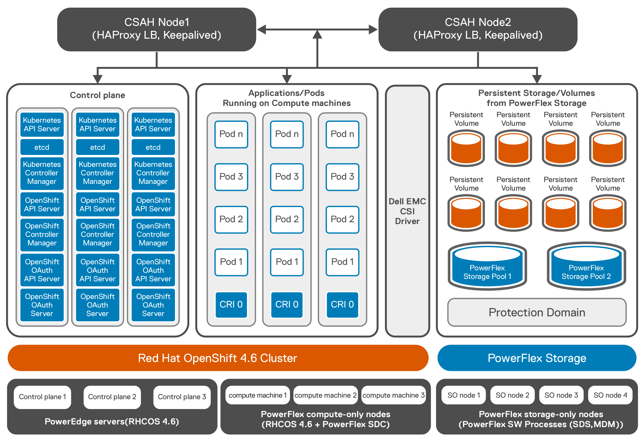 Logical architecture of Red Hat OpenShift 4.6.x deployed on PowerFlex
The following example shows OpenShift cluster with three master and eight worker nodes.
Once OpenShift installation is complete, CSI 1.4 is deployed on the OCP cluster. The CSI driver controller pod is deployed on one of the worker nodes and there are eight vxflexos-node pods that are deployed across eight worker nodes.
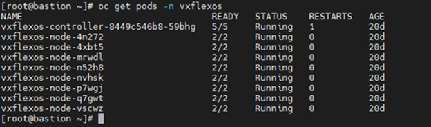
For more information about installation of CSI on OpenShift, see the GitHub page CSI installation.
Deploying Microsoft SQL Server BDC on OpenShift Container Platform
Microsoft SQL Server BDC cluster is deployed using OpenShift Container Platform as shown in the architecture diagram below by following instructions available at installation.
The following steps are performed to deploy Microsoft SQL Server BDC cluster using OpenShift Container Platform:
- The Azure Data CLI is installed on the client machine.
- All the pre-requisites for Microsoft SQL Server BDC on OpenShift cluster are performed. For this solution, openshift-prod was selected as the source for the configuration template from the list of available templates.
- All the OpenShift worker nodes are labeled before the Microsoft SQL Server BDC is installed.
- The control.json and bdc.json files are generated.
- The bdc.json is modified from the default settings to use cluster resources and to address the workload requirements. For example, the bdc.json looks like:
"spec": {
"type": "Master",
"replicas": 3,
"endpoints": [
{
"name": "Master",
"serviceType": "NodePort",
"port": 31433
},
{
"name": "MasterSecondary",
"serviceType": "NodePort",
"port": 31436
}
],
"settings": {
"sql": {
"hadr.enabled": "true"
}
},
……………
}
- The SQL image deployed in the control.json is 2019-CU9-ubuntu-16.04. To scale out the BDC resource pools, the number of replicas is adjusted to fully leverage the resources of the cluster. The following figure shows the logical architecture of Microsoft SQL Server BDC on OpenShift Container Platform with PowerFlex:7. SQL Server HA deployment is configured along with two data and two compute pods. Three storage pods are also configured. This type of configuration is used for TPC-C, and TPC-H like deployment as SQL is at HA mode with a single primary and couple of replicas. The following figure shows the pod placements across the eight worker nodes.
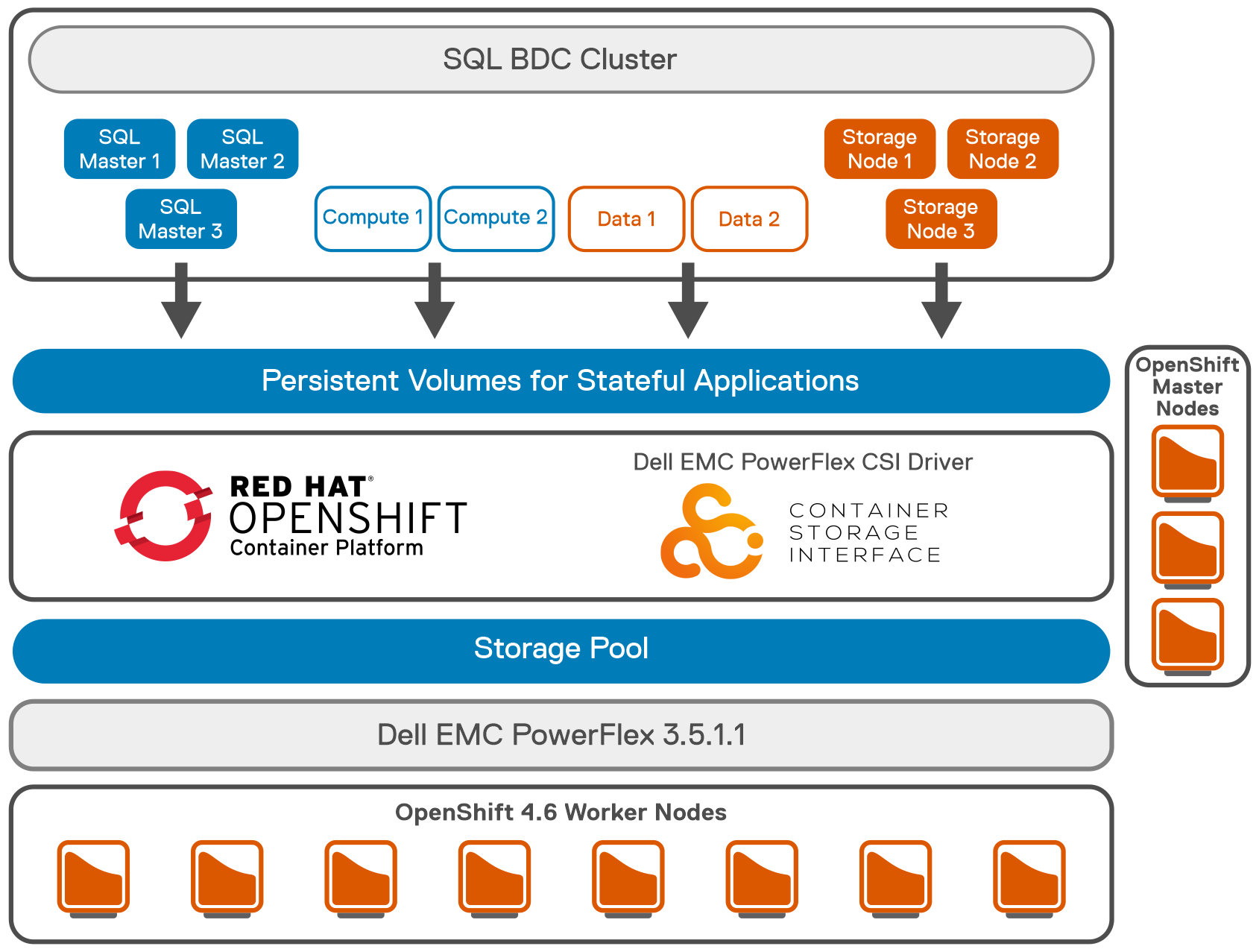 Logical architecture of Microsoft SQL Server BDC on OpenShift Container with PowerFlex
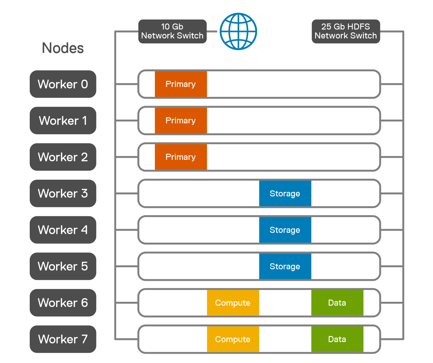 Pod placement across worker nodes
- To achieve the performance tuning of Microsoft SQL Server BDC cluster, see Microsoft performance guidelines.
- Tune the Microsoft SQL Server master instance based on the recommended guidelines.
- A testing tool like HammerDB documentation is run to validate the Microsoft SQL Server BDC for TPROC-H queries. HammerDB queries are run against the SQL Master instance.
- Follow the HammerDB best practices for SQL server guidelines to get the optimum performance. Although the results met the performance capabilities of the test system, the purpose of the testing was to validate Microsoft SQL Server BDC cluster and ensure that all best practices are implemented.
Conclusion
The validation was performed with a minimum lab hardware. For 1.2 TB of data loaded into Microsoft SQL Server, the QpH@Size was achieved at 220,800 for five virtual users as shown in the figure below. The overall test was completed for all the users in less than 30 minutes. It was observed that the PowerFlex system was not highly utilized while the test was carried out, including the PowerFlex storage, CPU, and memory, allowing the system to accommodate additional potential workload.
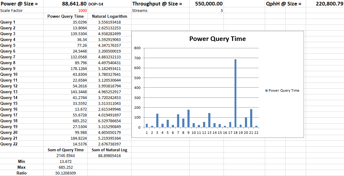 SQL Server BDC on PowerFlex validation
 The above test results show that SQL Server BDC deployed in a PowerFlex environment can provide a strong analytics platform for Data Warehousing type operations in addition to Big Data solutions.
To understand SQL Server BDC on upstream Kubernetes platform, see the paper SQL Server 2019 BDC on K8s.
References
Related Blog Posts

Deploying Microsoft SQL Server Big Data Clusters on Kubernetes platform using PowerFlex
Wed, 15 Dec 2021 12:20:15 -0000
|Read Time: 0 minutes
Introduction
Microsoft SQL Server 2019 introduced a groundbreaking data platform with SQL Server 2019 Big Data Clusters (BDC). Microsoft SQL Server Big Data Clusters are designed to solve the big data challenge faced by most organizations today. You can use SQL Server BDC to organize and analyze large volumes of data, you can also combine high value relational data with big data. This blog post describes the deployment of SQL Server BDC on a Kubernetes platform using Dell EMC PowerFlex software-defined storage.
PowerFlex
Dell EMC PowerFlex (previously VxFlex OS) is the software foundation of PowerFlex software-defined storage. It is a unified compute storage and networking solution delivering scale-out block storage service that is designed to deliver flexibility, elasticity, and simplicity with predictable high performance and resiliency at scale.
The PowerFlex platform is available in multiple consumption options to help customers meet their project and data center requirements. PowerFlex appliance and PowerFlex rack provide customers comprehensive IT Operations Management (ITOM) and life cycle management (LCM) of the entire infrastructure stack in addition to sophisticated high-performance, scalable, resilient storage services. PowerFlex appliance and PowerFlex rack are the preferred and proactively marketed consumption options. PowerFlex is also available on VxFlex Ready Nodes for those customers who are interested in software-defined compliant hardware without the ITOM and LCM capabilities.
PowerFlex software-define storage with unified compute and networking offers flexibility of deployment architecture to help best meet the specific deployment and architectural requirements. PowerFlex can be deployed in a two-layer for asymmetrical scaling of compute and storage for “right-sizing capacities, single-layer (HCI), or in mixed architecture.
Microsoft SQL Server Big Data Clusters Overview
Microsoft SQL Server Big Data Clusters are designed to address big data challenges in a unique way, BDC solves many traditional challenges through building big-data and data-lake environments. You can query external data sources, store big data in HDFS managed by SQL Server, or query data from multiple external data sources using the cluster.
SQL Server Big Data Clusters is an additional feature of Microsoft SQL Server 2019. You can query external data sources, store big data in HDFS managed by SQL Server, or query data from multiple external data sources using the cluster.
For more information, see the Microsoft page SQL Server Big Data Clusters partners.
You can use SQL Server Big Data Clusters to deploy scalable clusters of SQL Server and Apache SparkTM and Hadoop Distributed File System (HDFS), as containers running on Kubernetes.
For an overview of Microsoft SQL Server 2019 Big Data Clusters, see Microsoft’s Introducing SQL Server Big Data Clusters and on GitHub, see Workshop: SQL Server Big Data Clusters - Architecture.
Deploying Kubernetes Platform on PowerFlex
For this test, PowerFlex 3.6.0 is built in a two-layer configuration with six Compute Only (CO) nodes and eight Storage Only (SO) nodes. We used PowerFlex Manager to automatically provision the PowerFlex cluster with CO nodes on VMware vSphere 7.0 U2, and SO nodes with Red Hat Enterprise Linux 8.2.
The following figure shows the logical architecture of SQL Server BDC on Kubernetes platform with PowerFlex.
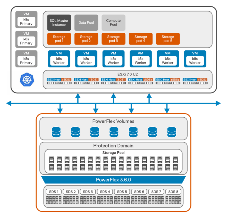
Figure 1: Logical architecture of SQL BDC on PowerFlex
From the storage perspective, we created a single protection domain from eight PowerFlex nodes for SQL BDC. Then we created a single storage pool using all the SSDs installed in each node that is a member of the protection domain.
After we deployed the PowerFlex cluster, we created eleven virtual machines on the six identical CO nodes with Ubuntu 20.04 on them, as shown in the following table.
Table 1: Virtual machines for CO nodes
Item | Node 1 | Node 2 | Node 3 | Node 4 | Node 5 | Node 6 |
Physical node | esxi70-1 | esxi70-2 | esxi70-3 | esxi70-4 | esxi70-5 | esxi70-6 |
H/W spec | 2 x Intel Gold 6242 R, 20 cores | 2 x Intel Gold 6242R, 20 cores | 2 x Intel Gold 6242R, 20 cores | 2 x Intel Gold 6242R, 20 cores | 2 x Intel Gold 6242R, 20 cores | 2 x Intel Gold 6242R, 20 cores |
Virtual machines | k8w1 | lb01 | lb02 | k8m1 | k8m2 | k8m3 |
k8w2 | k8w3 | k8w4 | k8w5 | k8w6 |
We manually installed the SDC component of PowerFlex on the worker nodes of Kubernetes. We then configured a Kubernetes cluster (v 1.20) on the virtual machines with three master nodes and eight worker nodes:
$ kubectl get nodes
NAME STATUS ROLES AGE VERSION
k8m1 Ready control-plane,master 10d v1.20.10
k8m2 Ready control-plane,master 10d v1.20.10
k8m3 Ready control-plane,master 10d v1.20.10
k8w1 Ready <none> 10d v1.20.10
k8w2 Ready <none> 10d v1.20.10
k8w3 Ready <none> 10d v1.20.10
k8w4 Ready <none> 10d v1.20.10
k8w5 Ready <none> 10d v1.20.10
k8w6 Ready <none> 10d v1.20.10
Dell EMC storage solutions provide CSI plugins that allow customers to deliver persistent storage for container-based applications at scale. The combination of the Kubernetes orchestration system and the Dell EMC PowerFlex CSI plugin enables easy provisioning of containers and persistent storage.
In the solution, after we installed the Kubernetes cluster, CSI 2.0 was provisioned to enable persistent volumes for SQL BDC workload.
For more information about PowerFlex CSI supported features, see Dell CSI Driver Documentation.
For more information about PowerFlex CSI installation using Helm charts, see PowerFlex CSI Documentation.
Deploying Microsoft SQL Server BDC on Kubernetes Platform
When the Kubernetes cluster with CSI is ready, Azure data CLI is installed on the client machine. To create base configuration files for deployment, see deploying Big Data Clusters on Kubernetes . For this solution, we used kubeadm-dev-test as the source for the configuration template.
Initially, using kubectl, each node is labelled to ensure that the pods start on the correct node:
$ kubectl label node k8w1 mssql-cluster=bdc mssql-resource=bdc-master --overwrite=true
$ kubectl label node k8w2 mssql-cluster=bdc mssql-resource=bdc-compute-pool --overwrite=true
$ kubectl label node k8w3 mssql-cluster=bdc mssql-resource=bdc-compute-pool --overwrite=true
$ kubectl label node k8w4 mssql-cluster=bdc mssql-resource=bdc-compute-pool --overwrite=true
$ kubectl label node k8w5 mssql-cluster=bdc mssql-resource=bdc-compute-pool --overwrite=true
$ kubectl label node k8w6 mssql-cluster=bdc mssql-resource=bdc-compute-pool --overwrite=true
To accelerate the deployment of BDC, we recommend that you use an offline installation method from a local private registry. While this means some extra work in creating and configuring a registry, it eliminates the network load of every BDC host pulling container images from the Microsoft repository. Instead, they are pulled once. On the host that acts as a private registry, install Docker and enable the Docker repository.
The BDC configuration is modified from the default settings to use cluster resources and address the workload requirements. For complete instructions about modifying these settings, see Customize deployments section in the Microsoft BDC website. To scale out the BDC resource pools, the number of replicas are adjusted to use the resources of the cluster.
The values shown in the following table are adjusted in the bdc.json file.
Table 2: Cluster resources
Resource | Replicas | Description |
nmnode-0 | 2 | Apache Knox Gateway |
sparkhead | 2 | Spark service resource configuration |
zookeeper | 3 | Keeps track of nodes within the cluster |
compute-0 | 1 | Compute Pool |
data-0 | 1 | Data Pool |
storage-0 | 5 | Storage Pool |
The configuration values for running Spark and Apache Hadoop YARN are also adjusted to the compute resources available per node. In this configuration, sizing is based on 768 GB of RAM and 72 virtual CPU cores available per PowerFlex CO node. Most of this configuration is estimated and adjusted based on the workload. In this scenario, we assumed that the worker nodes were dedicated to running Spark workloads. If the worker nodes are performing other operations or other workloads, you may need to adjust these values. You can also override Spark values as job parameters.
For further guidance about configuration settings for Apache Spark and Apache Hadoop in Big Data Clusters, see Configure Apache Spark & Apache Hadoop in the SQL Server BDC documentation section.
The following table highlights the spark settings that are used on the SQL Server BDC cluster.
Table 3: Spark settings
Settings | Value |
spark-defaults-conf.spark.executor.memoryOverhead | 484 |
yarn-site.yarn.nodemanager.resource.memory-mb | 440000 |
yarn-site.yarn.nodemanager.resource.cpu-vcores | 50 |
yarn-site.yarn.scheduler.maximum-allocation-mb | 54614 |
yarn-site.yarn.scheduler.maximum-allocation-vcores | 6 |
yarn-site.yarn.scheduler.capacity.maximum-am- resource-percent | 0.34 |
The SQL Server BDC 2019 CU12 release notes state that Kubernetes API 1.20 is supported. Therefore, for this test, the image that was deployed on the SQL master pod was 2019-CU12-ubuntu-16.04. A storage of 20 TB was provisioned for SQL master pod, with 10 TB as log space:
"nodeLabel": "bdc-master",
"storage": {
"data": {
"className": "vxflexos-xfs",
"accessMode": "ReadWriteOnce",
"size": "20Ti"
},
"logs": {
"className": "vxflexos-xfs",
"accessMode": "ReadWriteOnce",
"size": "10Ti"
}
}
Because the test involved running the TPC-DS workload, we provisioned a total of 60 TB of space for five storage pods:
"storage-0": {
"metadata": {
"kind": "Pool",
"name": "default"
},
"spec": {
"type": "Storage",
"replicas": 5,
"settings": {
"spark": {
"includeSpark": "true"
}
},
"nodeLabel": "bdc-compute-pool",
"storage": {
"data": {
"className": "vxflexos-xfs",
"accessMode": "ReadWriteOnce",
"size": "12Ti"
},
"logs": {
"className": "vxflexos-xfs",
"accessMode": "ReadWriteOnce",
"size": "4Ti"
}
}
}
}
Validating SQL Server BDC on PowerFlex
To validate the configuration of the Big Data Cluster that is running on PowerFlex and to test its scalability, we ran the TPC-DS workload on the cluster using the Databricks® TPC-DS Spark SQL kit. The toolkit allows you to submit an entire TPC-DS workload as a Spark job that generates the test dataset and runs a series of analytics queries across it. Because this workload runs entirely inside the storage pool of the SQL Server Big Data Cluster, the environment was scaled to run the recommended maximum of five storage pods.
We assigned one storage pod to each worker node in the Kubernetes environment as shown in the following figure.
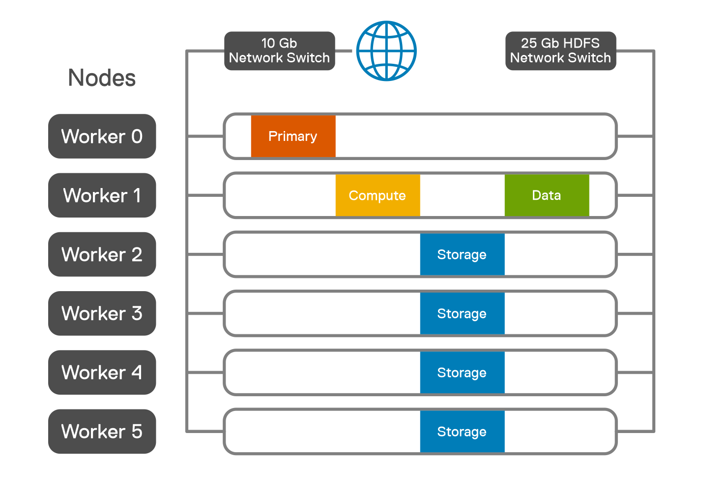
Figure 2: Pod placement across worker nodes
In this solution, Spark SQL TPC-DS workload is adopted to simulate a database environment that models several applicable aspects of a decision support system, including queries and data maintenance. Characterized by high CPU and I/O load, a decision support workload places a load on the SQL Server BDC cluster configuration to extract maximum operational efficiencies in areas of CPU, memory, and I/O utilization. The standard result is measured by the query response time and the query throughput.
A Spark JAR file is uploaded into a specified directory in HDFS, for example, /tpcds. The spark-submit is done by CURL, which uses the Livy server that is part of Microsoft SQL Server Big Data Cluster.
Using the Databricks TPC-DS Spark SQL kit, the workload is run as Spark jobs for the 1 TB, 5 TB, 10 TB, and 30 TB workloads. For each workload, only the size of the dataset is changed.
The parameters used for each job are specified in the following table.
Table 4: Job parameters
Parameter | Value |
spark-defaults-conf.spark.driver.cores | 4 |
spark-defaults-conf.spark.driver.memory | 8 G |
spark-defaults-conf.spark.driver.memoryOverhead | 484 |
spark-defaults-conf.spark.driver.maxResultSize | 16 g |
spark-defaults-conf.spark.executor.instances | 12 |
spark-defaults-conf.spark.executor.cores | 4 |
spark-defaults-conf.spark.executor.memory | 36768 m |
spark-defaults-conf.spark.executor.memoryOverhead | 384 |
spark.sql.sortMergeJoinExec.buffer.in.memory.threshold | 10000000 |
spark.sql.sortMergeJoinExec.buffer.spill.threshold | 60000000 |
spark.shuffle.spill.numElementsForceSpillThreshold | 59000000 |
spark.sql.autoBroadcastJoinThreshold | 20971520 |
spark-defaults-conf.spark.sql.cbo.enabled | True |
spark-defaults-conf.spark.sql.cbo.joinReorder.enabled | True |
yarn-site.yarn.nodemanager.resource.memory-mb | 440000 |
yarn-site.yarn.nodemanager.resource.cpu-vcores | 50 |
yarn-site.yarn.scheduler.maximum-allocation-mb | 54614 |
yarn-site.yarn.scheduler.maximum-allocation-vcores | 6 |
We set the TPC-DS dataset with the different scale factors in the CURL command. The data was populated directly into the HDFS storage pool of the SQL Server Big Data Cluster.
The following figure shows the time that is consumed for data generation of different scale factor settings. The data generation time also includes the post data analysis process that calculates the table statistics.
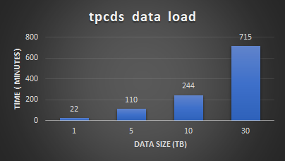
Figure 3: TPC-DS data generation
After the load we ran the TPC-DS workload to validate the Spark SQL performance and scalability with 99 predefined user queries. The queries are characterized with different user patterns.
The following figure shows the performance and scalability test results. The results demonstrate that running Microsoft SQL Server Big Data Cluster on PowerFlex has linear scalability for different datasets. This shows the ability of PowerFlex to provide a consistent and predictable performance for different types of Spark SQL workloads.
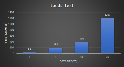
Figure 4: TPC-DS test results
A Grafana dashboard instance that is captured during the 30 TB run of TPC-DS test is shown in the following figure. The figure shows that the read bandwidth of 15 GB/s is achieved during the tests.
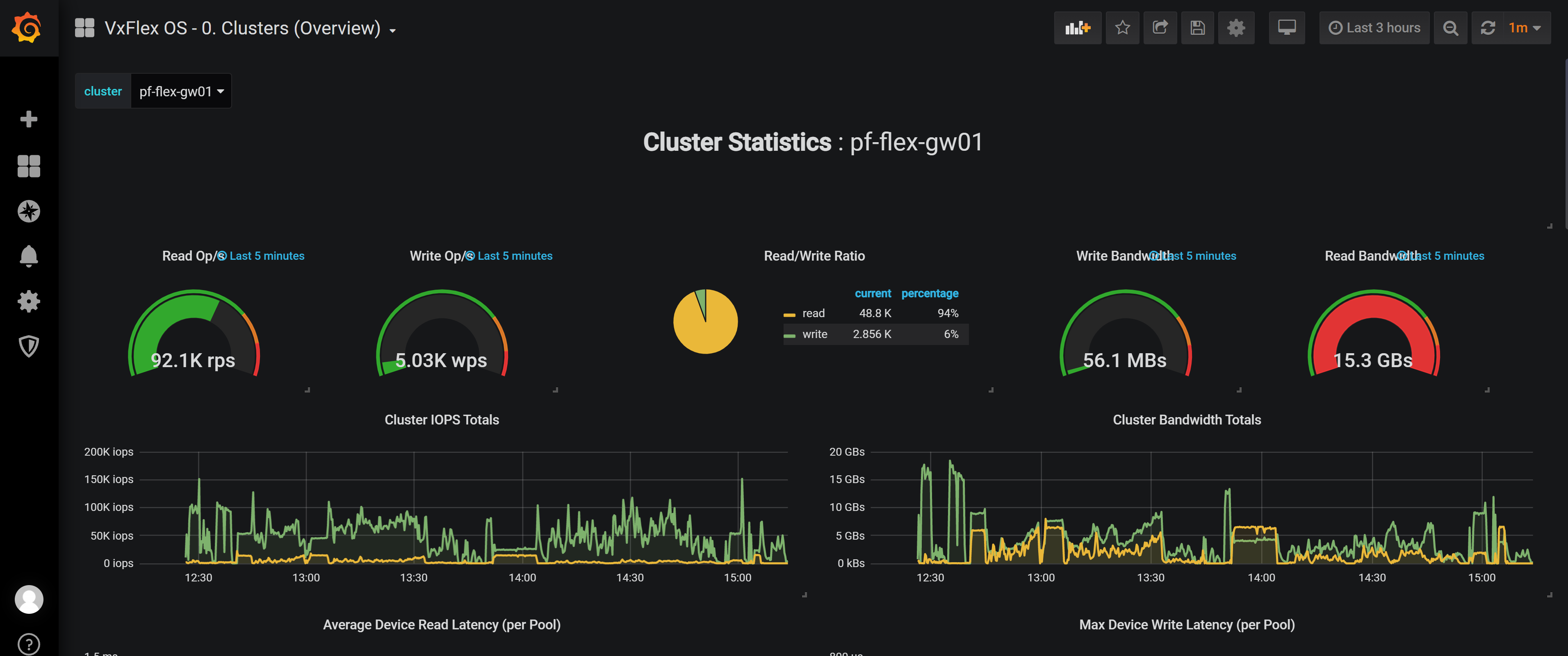
Figure 5: Grafana dashboard
In this minimal lab hardware, there were no storage bottlenecks for the TPC-DS data load and query execution. The CPU on the worker nodes reached close to 90 percent indicating that more powerful nodes could enhance the performance.
Conclusion
Running SQL Server Big Data Clusters on PowerFlex is a straightforward way to get started with modernized big data workloads running on Kubernetes. This solution allows you to run modern containerized workloads using the existing IT infrastructure and processes. Big Data Clusters allows Big Data scientists to innovate and build with the agility of Kubernetes, while IT administrators manage the secure workloads in their familiar vSphere environment.
In this solution, Microsoft SQL Server Big Data Clusters are deployed on PowerFlex which provides the simplified operation of servicing cloud native workloads and can scale without compromise. IT administrators can implement policies for namespaces and manage access and quota allocation for application focused management. Application-focused management helps you build a developer-ready infrastructure with enterprise-grade Kubernetes, which provides advanced governance, reliability, and security.
Microsoft SQL Server Big Data Clusters are also used with Spark SQL TPC-DS workloads with the optimized parameters. The test results show that Microsoft SQL Server Big Data Clusters deployed in a PowerFlex environment can provide a strong analytics platform for Big Data solutions in addition to data warehousing type operations.
For more information about PowerFlex, see Dell EMC PowerFlex. For more information about Microsoft SQL Server Big Data Clusters, see Introducing SQL Big Data Clusters.
If you want to discover more, contact your Dell representative.
References

CSM 1.8 Release is Here!
Fri, 22 Sep 2023 21:29:12 -0000
|Read Time: 0 minutes
Introduction
This is already the third release of Dell Container Storage Modules (CSM)!
The official changelog is available in the CHANGELOG directory of the CSM repository.
CSI Features
Supported Kubernetes distributions
The newly supported Kubernetes distributions are :
- Kubernetes 1.28
- OpenShift 4.13
SD-NAS support for PowerMax and PowerFlex
Historically, PowerMax and PowerFlex are Dell’s high-end and SDS for block storage. Both of these backends recently introduced support for software defined NAS.
This means that the respective CSI drivers can now provision PVC with the ReadWriteMany access mode for the volume type file. In other words, thanks to the NFS protocol different nodes from the Kubernetes cluster can access the same volume concurrently. This feature is particularly useful for applications, such as log management tools like Splunk or Elastic Search, that need to process logs coming from multiple Pods.
CSI Specification compliance
Storage capacity tracking
Like PowerScale in v1.7.0, PowerMax and Dell Unity allow you to check the storage capacity on a node before deploying storage to that node. This isn't that relevant in the case of shared storage, because shared storage generally will always show the same capacity to each node in the cluster. However, it could prove useful if the array lacks available storage.
Using this feature, an object from the CSIStorageCapacity type is created by the CSI driver in the same namespace as the CSI driver, one for each storageClass.
An example:
kubectl get csistoragecapacities -n unity # This shows one object per storageClass.
Volume Limits
The Volume Limits feature is added to both PowerStore and PowerFlex. All Dell storage platforms now implement this feature.
This option limits the maximum number of volumes to which a Kubernetes worker node can connect. This can be configured on a per-node basis, or cluster-wide. Setting this variable to zero disables the limit.
Here are some PowerStore examples.
Per node:
kubectl label node <node name> max-powerstore-volumes-per-node=<volume_limit>
For the entire cluster (all worker nodes):
Specify maxPowerstoreVolumesPerNode or maxVxflexVolumesPerNode in the values.yaml file upon Helm installation.
If you opted-in for the CSP Operator deployment, you can control it by specifying X_CSI_MAX_VOLUMES_PER_NODES in the CRD.
Useful links
Stay informed of the latest updates of the Dell CSM eco-system by subscribing to:
- The Dell CSM Github repository
- Our DevOps & Automation Youtube playlist
- Slack (under the Dell Infrastructure namespace)
- Live streaming on Twitch
Author: Florian Coulombel