


Dell Technologies PowerEdge MX platform: I/O Module and Fibre Channel Switch Module Replacement Process
The Dell PowerEdge MX platform with OME-M 1.30.00 and later enables you to replace the MX I/O Module (IOM) and MX Fibre Channel (FC) switch module. This capability lets you recover from persistent errors, hardware failure, or other valid reasons. You can replace the IOM through an OME-M Graphical User Interface (GUI) in SmartFabric mode, or you can replace it manually through the Command Line Interface (CLI) in Full Switch mode.
This blog describes how to:
- Replace the MX IOM in SmartFabric mode.
- Replace the MX IOM in Full Switch mode.
- Replace the MXG610S FC switch module.
Note: Before starting the MX module switch replacement process, contact Dell Technical Support. For technical support, go to https://www.dell.com/support or call (USA) 1-800-945-3355.
Note: The new IOM includes OS10 factory default version and settings, and all ports are in no shutdown mode by default.
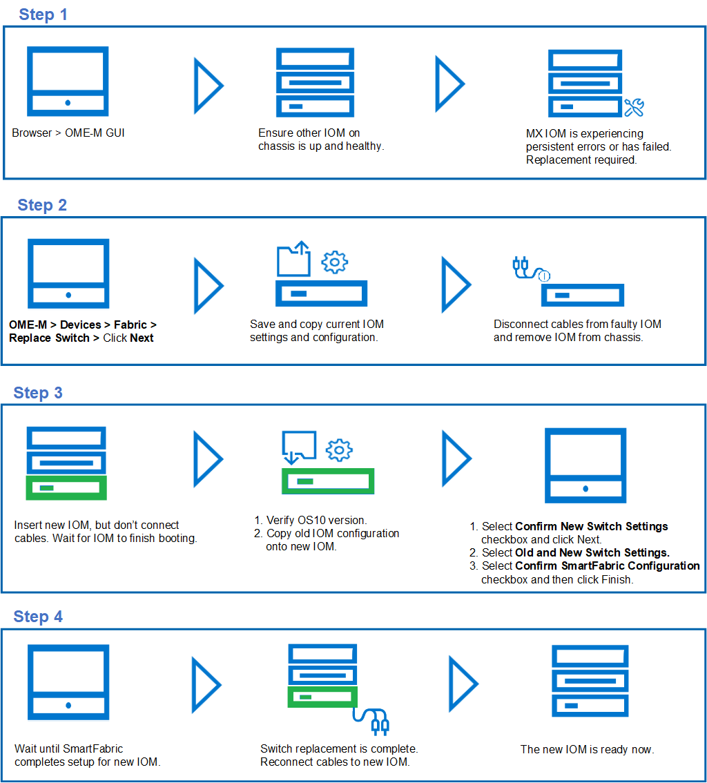
MX I/O Module replacement process in SmartFabric Mode
- Once the SmartFabric is created, you can only perform the IOM replacement process through the OME-M GUI.
- The IOM must be replaced with another IOM of the same type.
- Ensure that the OS10 version on the new IOM is identical to the OS10 version of the IOM being replaced.
- If the new OS10 version does not match another existing IOM in the chassis, then cancel the OME-M replacement wizard and upgrade or downgrade the new IOM OS10 firmware to match.
- Once the OME-M replacement wizard completes setup for the new IOM, connect all the cables to the new IOM.
Note: As a best practice, manually back up the IOM startup configuration on a regular basis. If a configuration is not available for the faulty IOM, you must configure the IOM through the standard initial setup process.
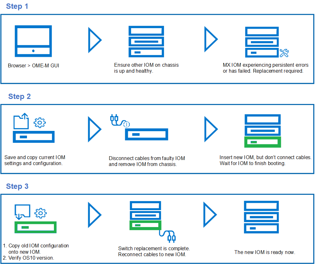
MX I/O Module replacement process in Full Switch Mode
- Before replacing the faulty IOM, ensure that the other IOM on the chassis is up, healthy, and in Full Switch mode. A complete network traffic outage might occur if these conditions are not met.
- The IOM must be replaced with another IOM of the same type.
- The OS10 firmware is factory-installed in the MX9116n Fabric Switching Engine (FSE) and in the MX5108 Ethernet Switch.
- Ensure that the OS10 version on the new IOM is identical to the OS10 version of the IOM being replaced.
- If the new OS10 version does not match another existing IOM in the chassis, then cancel the OME-M replacement wizard and upgrade or downgrade the new IOM OS10 firmware to match.
- Once the OME-M completes setup for the new IOM, connect all the cables to the new IOM.
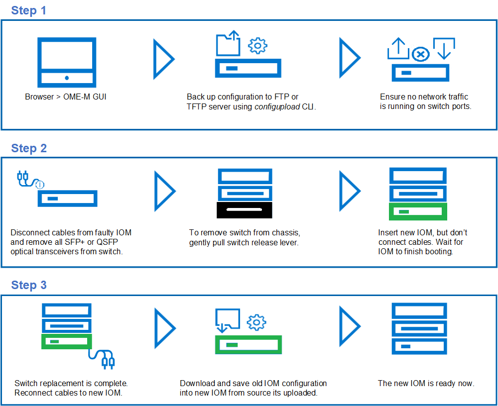
MXG610S Fibre Channel Switch module replacement process
The PowerEdge MX platform allows replacement of an MXG610s FC switch module. The MXG610 has a flexible architecture which enables dynamic scale connectivity and bandwidth with the latest generation of Fibre Channel for the PowerEdge MX7000 platform. The MXG610 features up to 32 Fibre Channel ports, which auto-negotiate to 32, 16, or 8 Gbps speed.
Note: Never leave the slot on the blade server chassis open for an extended period. To maintain proper airflow, fill the slot with either a replacement switch module or filler blade.
Note: As a best practice, manually backup the IOM startup configuration on a regular basis. If a configuration is not available for the faulty IOM, you must configure the IOM through the standard initial setup process.
References:
MX SmartFabric mode IOM replacement process
MX Full Switch mode IO module replacement process
MXG610 Fibre Channel switch module replacement process
Upgrading Dell EMC SmartFabric OS10
Manual backup of IOM configuration through the CLI
Interactive Demo: OpenManage Enterprise Modular for MX solution management
Related Blog Posts

Dell Technologies PowerEdge MX Platform: NPAR
Mon, 22 May 2023 18:49:51 -0000
|Read Time: 0 minutes
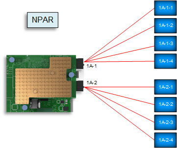
Network interface card partitioning (NPAR) allows users to minimize the implementation of physical Network interface cards (NICs) and separates Local Area Network (LAN) and Storage Area Network (SAN) connections. NPAR improves bandwidth allocation, network traffic management, and utilization in virtualized and non-virtualized network environments. The number of physical servers may be fewer, but the demand for the NIC ports is more.
The NPAR feature allows you to use a single physical network adapter for multiple logical networking connections.
 NIC with NPAR enabled
 Creating multiple virtual NICs for different applications uses Operating System (OS) resources. Deploying NPAR on the NIC will reduce the OS resource consumption and put most of the load on the NIC itself.
Note: Not every implementation requires NPAR. NPAR benefits depend on the server NIC and the network traffic that should run on that NIC.
 NIC with NPAR enabled
This blog describes how to validate, enable, and configure NPAR on a Dell PowerEdge MX Platform through the server System Setup and the MX compute sled Server Templates within Dell Open Manage Enterprise – Modular (OME-M).
The MX750c compute sled and QLogic-41262 Converged Network Adapter (CNA) have been used in the deployment example described throughout this blog.
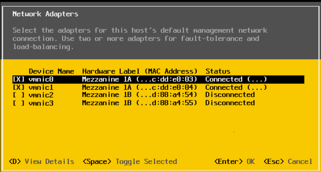
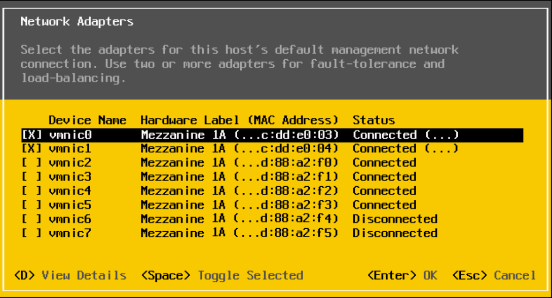
Validating the NIC port without NPAR enabled
NPAR is not enabled by default on the MX compute sled NIC. This section demonstrates how to verify the current settings through the following methods:
- Server Integrated Dell Remote Access Controller (iDRAC)
- MX OME-M
- Windows operating system
- VMware vSphere ESXi
Note: The following figures show NIC status without NPAR enabled for all the techniques.
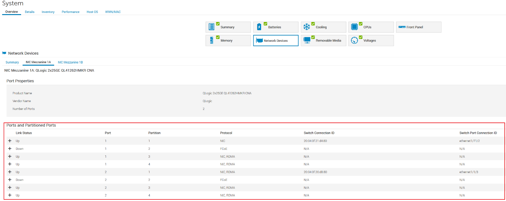
Server iDRAC
- Open the server Integrated Dell Remote Access Controller (iDRAC).
- Click System > Overview > Network Devices.
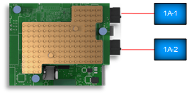
The partition is Disabled for port-1 and port-2 of NIC Mezzanine 1A, as shown in the figure below.
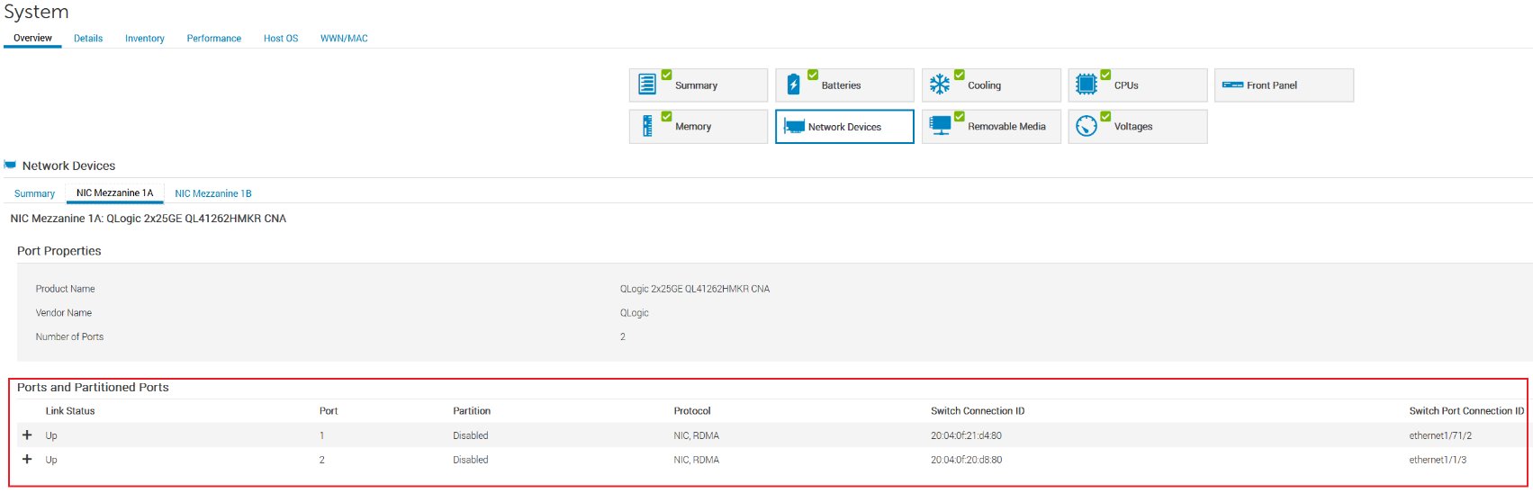
MX 750c Sled server iDRAC settings
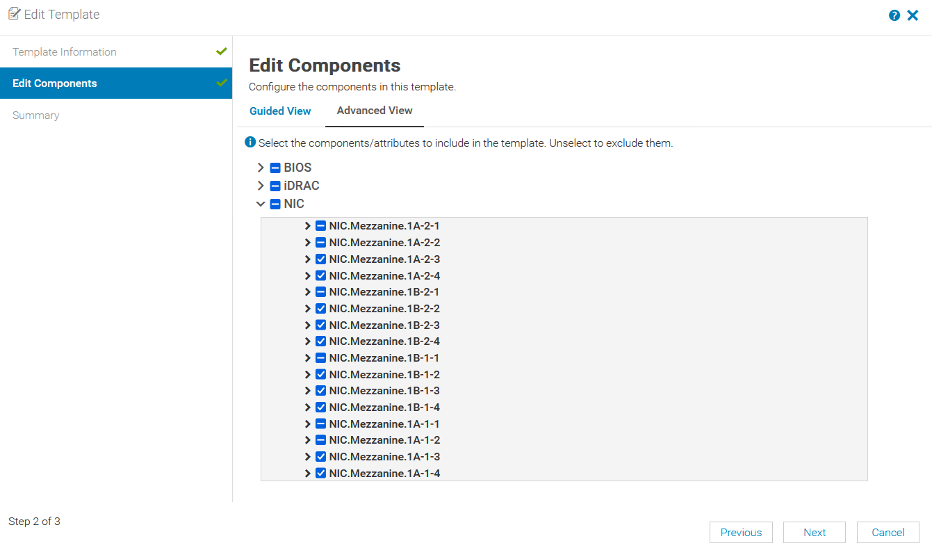
MX OME-M
- In OME-M, select Configuration > Template.
- In the Edit Template window, select the server template and then click Edit > Next.
- On the Edit Components page, select the Advanced View tab.
No partitions are enabled for port-1 and port-2 of NIC Mezzanine 1A, as shown in the figure below.
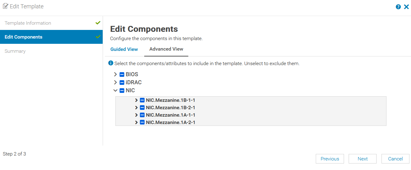
OME-M server Edit Template settings
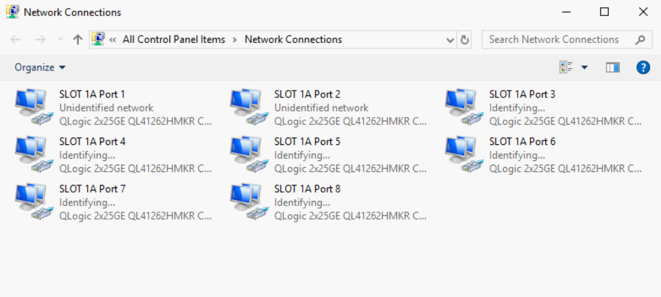
Windows operating system
- Log into Windows Server.
- Open the Windows Control Panel.
- Click Network and Sharing Center > Change adapter settings.
No partitions are enabled for NIC SLOT 1A, port-1 and port-2, as shown in the figure below.
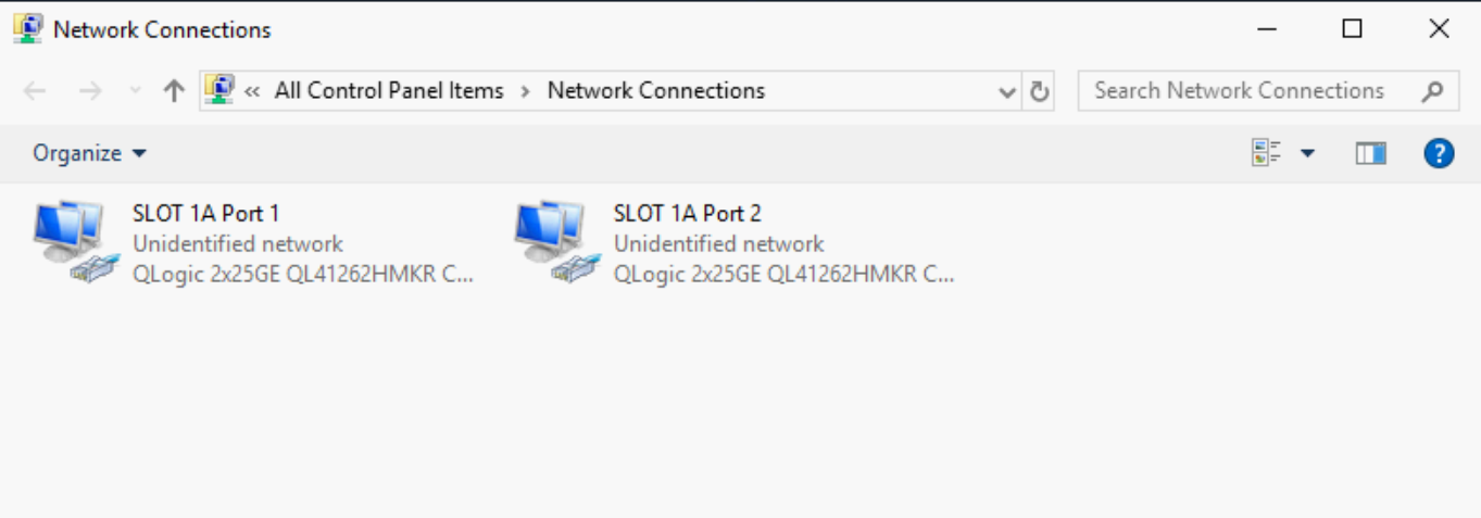
Windows Network adapter settings
VMware vSphere ESXi
- Log into the VMware host server.
- Click Configure Management Network > Network Adapters.
No partitions are enabled for port-1 and port-2 of NIC Mezzanine 1A, as shown in the figure below.
VMware Network Adapters settings
Configure NPAR Device Settings and NIC Partitioning
You can configure NPAR device settings and NIC Partitioning on the MX compute sled through the server System Setup wizard.
The QLogic-41262 CNA shown in this example supports eight partitions per CNA port. In the following deployment example, we create four NIC partitions. However, only two partitions are used: one for Ethernet traffic and one for FCoE traffic.
System Setup wizard
To enable and configure NPAR on a server NIC through the System Setup wizard:
- In OME-M, select Compute.
- Select the required server.
- In the URL field, enter the IP address for the server.
- Open the Virtual Console.
- From the menu at the top of the window, click Next Boot.
- Select BIOS Setup and click OK.
- To reboot the server:
- From the menu at the top of the window, click Power.
- Select Reset System (warm boot) and then click Yes.
Device Settings
To configure the device settings:
- From the System Setup main menu, select Device Settings.
- Select Port-1 from mezzanine 1A of the CNA.
The Main Configuration page displays. - To enable Virtualization Mode:
- Click Device Level Configuration.
- From the Virtualization Mode list, select NPar.
- Click Back.
Note: Do not enable NParEP-Mode. Enabling NParEP-Mode will create eight partitions per CNA port.
NIC Partitioning Configuration
To configure NIC partitioning for Partition 1:
- Click NIC Partitioning Configuration.
- Select Partition 1 Configuration.
- Validate NIC is set to Enabled.
- Set NIC + RDMA Mode to Disabled.
- Click Back.
To configure NIC partitioning for Partition 2:
- Select Partition 2 Configuration.
- Set FCoE Mode to Enabled.
- Click Back to return to the Main Configuration Page.
- To set the boot protocol:
- Select NIC Configuration.
- Set Boot Protocol to UEFI FCoE.
- To enable FCoE Configuration:
- Select FCoE Configuration.
- Set Connect 1 to Enabled.
- Click Back.
In this example partition-3 and partition-4 are not used. To disable NPar for Partition 3 and 4:
- Click NIC Partitioning Configuration.
- Set NIC partition-3 Mode to Disabled and click Back.
- Set NIC partition-4 Mode to Disabled and click Back.
- Click Back and then click Finish.
- To save the changes, click Yes.
- On the Success window, click OK.
The Device Settings Page displays. - To return to the System Setup Main Menu, click Finish.
Configure second CNA port
To configure the second CNA port:
- From the System Setup main menu, select Device Settings.
- Select Port-2 from mezzanine 1A of the CNA.
The Main Configuration page displays. - Repeat the steps in the previous sections, Device Settings and NIC Partitioning Configuration.
- To reboot the server:
- Click Finish.
- On the Confirm Exit window, click Yes.
Confirm NPAR status
The MX compute sled NIC is now configured for NPAR. The following sections describe how to confirm the NIC status with NPAR enabled.
Server iDRAC
To confirm the NPAR status on the server iDRAC:
- Open the server iDRAC.
- Click System > Overview > NetworkDevices.
Port-1 and port-2 of NIC Mezzanine 1A have four partitions for each NIC port, as shown in the following figure.
MX 740c Sled server iDRAC settings
MX OME-M
To confirm the NPAR status in OME-M:
- In OME-M, select Configuration > Template.
- In the Edit Template window, select the server template and then click Edit > Next.
- On the Edit Components page, select the Advanced View tab.
Partitions for NIC port-1 and port-2 of NIC Mezzanine 1A have been enabled, as shown in the figure below.
MX OME-M Compute Sled NIC-NPAR enabled
Windows operating system
To confirm the NPAR status in the Windows Control Panel:
- Log into Windows Server.
- Open the Windows Control Panel.
- Click Network and Sharing Center > Change adapter settings.
NIC Mezzanine 1A has four partitions for each NIC port, as shown in the figure below.
Windows Network adapter settings
VMware vSphere ESXi
To confirm the NPAR status in VMware vSphere ESXi:
- Log into the VMware host server.
- Click Configure Management Network > Network Adapters.
The partitions for port-1 and port-2 of NIC Mezzanine 1A, as shown in the figure below.
VMware Network adapters settings
Configure NIC Partitioning with a template in OME-M
OME-M 1.40.00 introduces NPAR NIC configurations in the MX compute sled server template GUI. To configure NPAR settings on the PowerEdge MX platform, you must have administrator access.
Note: Ensure NPAR is enabled through System Setup before using the MX server template GUI for NPAR settings. The MX server template GUI allows users to modify the NIC attributes. To configure NPAR attributes on the MX compute sled using the server template GUI:
- Open the OME-M console.
- If NPAR is configured on an existing server template, proceed to step 10.
- If NPAR is not configured on an existing server template, from the navigation menu, select Configuration, then click Templates.
Note: With OME-M 1.20.10 and earlier, the Templates option is called Deploy. - From the center panel, click Create Template, then click From Reference Device to open the Create Template window.
- In the Template Name box, enter a name.
- Optionally, enter a description in the Description box, then click Next.
- In the Device Selection section, click Select Device.
- Select the compute sled from the desired chassis and click Finish.
- To complete the compute selection for server template, click Finish.
The server template status shows Running and then displays Completed after the process completes. - Select the server template.
- Click Edit and then click Next.
- On the Edit Components page, select the Advanced View tab.
- Expand the NIC and the NIC port as shown in the figure below.
- Expand the desired NIC Port and expand Device Level Configuration. Verify the Virtualization Mode is set to NPAR.
- Expand the NIC Configuration and set Boot Protocol to UEFI FCoE.
- Expand the NIC Partitioning Configuration and set NIC + RDMA Mode to Disabled.
- Expand the FCoE menu and set Connect to Enabled.
- Click Next.
- Click Finish.
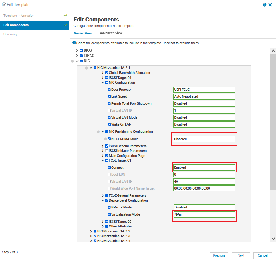
OME-M Server Template Edit settings
Server Template Profile
The PowerEdge MX platform supports profiles with OME-M 1.30.00 and later. OME-M creates and automatically assigns a profile once the server template is deployed successfully. Profiles can be used to deploy with modified attributes on server templates, including NPAR settings. A single profile can be applied to multiple server templates with only modified attributes, or with all attributes.
The following figure shows two profiles from template deployments that have been created and deployed.
Note: The server template cannot be deleted until it is unassigned from a profile.
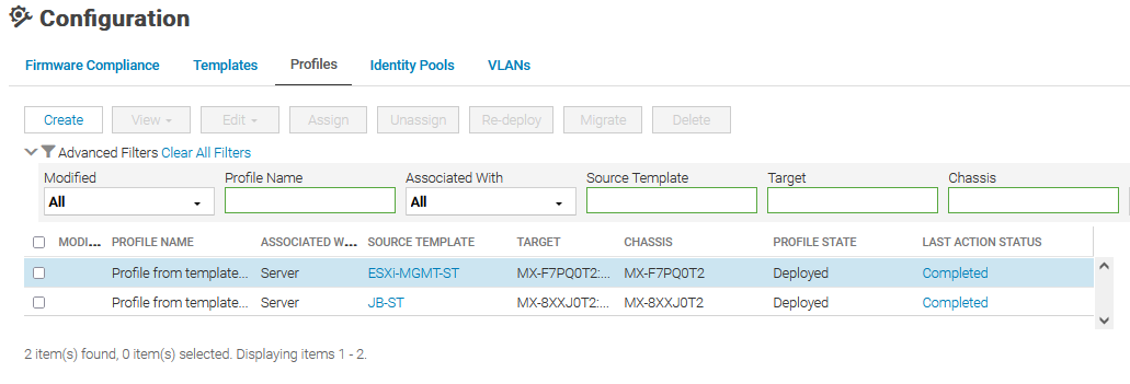
MX Server Template Profiles
Choosing a NIC
The following sections provide information to assist in choosing the appropriate NIC for your environment.
PowerEdge MX Ethernet Mezzanine Cards
The following table shows NPAR support details for MX-qualified NICs:
Vendor | Model | Max Speed | Ports | NIC Type | NPAR | Number of Partitions |
Marvell/QLogic | QL41262 | 10/25GbE | 2 | CNA | Yes | 8/port – Total 16 |
Marvell/QLogic | QL41232 | 10/25GbE | 2 | NIC | Yes | 8/port – Total 16 |
Broadcom | 57504 | 10/25GbE | 4 | NIC | Yes | 4/port – Total 16 |
Intel | XXV710 | 10/25GbE | 2 | NIC | No | N/A |
Mellanox | ConnectX-4 LX | 10/25GbE | 2 | NIC | No | N/A |
Comparison of NIC NPAR and Cisco Virtual Interface Card (VIC)
NIC NPAR and Cisco VIC both provide multiple network connections using limited physical ports of the NIC. In the comparison table below, some key differences between NIC NPAR and Cisco VIC are highlighted.
NIC NPAR | Cisco VIC
|
Industry standard. Works with any supported network switch. | Cisco proprietary LAN and SAN interface card for UCS and modular servers. |
Up to four or up to eight physical function vNIC per adapter port. | Up to 256 PCI-e devices can be configured. Physical limitation on performance of the traffic based on the available bandwidth from the network link. |
Configured in BIOS or iDRAC found in the server. | Requires UCS Fabric Interconnect to associate vNIC ports. |
MAC and Bandwidth allotment assigned and configured in BIOS. | MAC and Bandwidth allotment are determined by a service profile. |
NIC port enumeration is predictable and provides uniform device name assignments across a population of identical and freshly deployed in ESXi host. | Cisco UCS can manage the order that NICs are enumerated in ESXi. |
NIC teaming options on the MX Platform
Below are the NIC teaming options available on MX compute sleds.
Teaming option | Description |
No teaming | No NIC bonding, teaming, or switch-independent teaming |
LACP teaming | LACP (Also called 802.3ad or dynamic link aggregation.) NOTE: LACP Fast timer is not currently supported. |
Other | Other NOTE: If using the Broadcom 57504 Quad-Port NIC and two separate LACP groups are needed, select this option, and configure the LACP groups in the Operating System. Otherwise, this setting is not recommended as it can have a performance impact on link management. |
Restrictions
- The following restrictions apply for both Full Switch and SmartFabric modes:
- If NPAR is not in use, both switch-dependent (LACP and static LAG) and switch-independent teaming methods are supported.
- If NPAR is in use, only switch-independent teaming methods are supported. Switch-dependent teaming (LACP and static LAG) is not supported.
- If switch dependent (LACP) teaming is used, the following restrictions apply:
- The iDRAC shared LAN on motherboard (LOM) feature can only be used if the Failover option on the iDRAC is enabled.
- If the host operating system is Microsoft Windows, the LACP timer MUST be set to Slow, also referred to as Normal.
- In SmartFabric mode when an imported template is deployed where NPAR is enabled, it does not configure the bandwidth settings for IOMs.
References
Profiles Deployment: Profiles with server template deployment
VMware knowledge base: How VMware ESXi determines the order in which names are assigned to devices (2091560)
Dell EMC OpenManage Enterprise-Modular Edition for PowerEdge MX7000 Chassis User's Guide

Dell Technologies PowerEdge MX 100 GbE solution with external Fabric Switching Engine
Mon, 26 Jun 2023 20:31:38 -0000
|Read Time: 0 minutes
The Dell PowerEdge MX platform is advancing its position as the leading high-performance data center infrastructure by introducing a 100 GbE networking solution. This evolved networking architecture not only provides the benefit of 100 GbE speed but also increases the number of MX7000 chassis within a Scalable Fabric. The 100 GbE networking solution brings a new type of architecture, starting with an external Fabric Switching Engine (FSE).
PowerEdge MX 100 GbE solution design example
The diagram shows only one connection on each MX8116n for simplicity. See the port-mapping section in the networking deployment guide here.
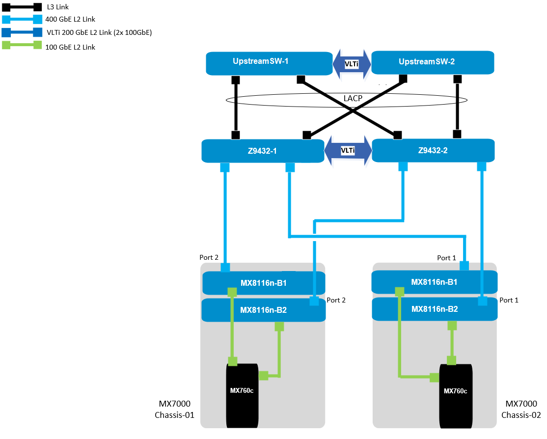
Figure 1. 100 GbE solution example topology
Components for 100 GbE networking solution
The key hardware components for 100 GbE operation within the MX Platform are described below with a minimal description.
Dell Networking MX8116n Fabric Expander Module
The MX8116n FEM includes two QSFP56-DD interfaces, with each interface providing up to 4x 100Gbps connections to the chassis, 8x 100 GbE internal server-facing ports for 100 GbE NICs, and 16x 25 GbE for 25 GbE NICs.
The MX7000 chassis supports up to four MX8116n FEMs in Fabric A and Fabric B.
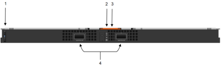
Figure 2. MX8116n FEM
The following MX8116n FEM components are labeled in the preceding figure:
- Express service tag
- Power and indicator LEDs
- Module insertion and removal latch
- Two QSFP56-DD fabric expander ports
Dell PowerEdge MX760c compute sled
- The MX760c is ideal for dense virtualization environments and can serve as a foundation for collaborative workloads.
- Businesses can install up to eight MX760c sleds in a single MX7000 chassis and combine them with compute sleds from different generations.
- Single or dual CPU (up to 56 cores per processor/socket with four x UPI @ 24 GT/s) and 32x DIMM slots DDR5 with eight memory channels.
- 8x E3.S NVMe (Gen5 x4) or 6 x 2.5" SAS/SATA SSDs or 6 x NVMe (Gen4) SSDs and iDRAC9 with lifecycle controller.
Note: The 100 GbE Dual Port Mezzanine card is also available on the MX750c.
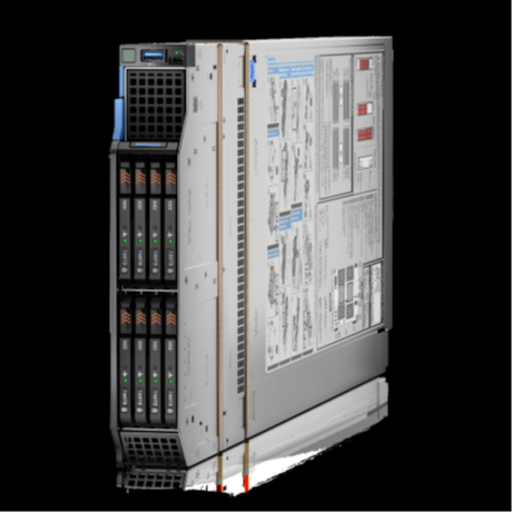
Figure 3. Dell PowerEdge MX760c sled with eight E3.s SSD drives
Dell PowerSwitch Z9432F-ON external Fabric Switching Engine
The Z9432F-ON provides state-of-the-art, high-density 100/400 GbE ports, and a broad range of functionality to meet the growing demands of modern data center environments. Compact and offers an industry-leading density of 32 ports of 400 GbE in QSFP56-DD, 128 ports of 100, or up to 144 ports of 10/25/50 (through breakout) in a 1RU design. Up to 25.6 Tbps non-blocking (full duplex), switching fabric delivers line-rate performance under full load.L2 multipath support using Virtual Link Trunking (VLT) and Routed VLT support. Scalable L2 and L3 Ethernet switching with QoS and a full complement of standards-based IPv4 and IPv6 features, including OSPF and BGP routing support.

Figure 4. Dell PowerSwitch Z9432F-ON
Note: Mixed dual port 100 GbE and quad port 25 GbE mezzanine cards connecting to the same MX8116n are not a supported configuration.
100 GbE deployment options
There are four deployment options for the 100 GbE solution, and every option requires servers with a dual port 100 GbE mezzanine card. You can install the mezzanine card in either mezzanine slot A, B, or both. When you use the Broadcom 575 KR dual port 100 GbE mezzanine card, you should set the Z9432F-ON port-group to unrestricted mode and configure the port mode for 100g-4x.
PowerSwitch CLI example:
port-group 1/1/1
profile unrestricted
port 1/1/1 mode Eth 100g-4x
port 1/1/2 mode Eth 100g-4x
Note: The 100 GbE solution deployment, 14 maximum numbers of chassis are supported in single fabric, and 7 maximum numbers of chassis are supported in dual fabric using the same pair of FSE solution.
Single fabric
In a single fabric deployment, two MX8116n can be installed either in Fabric A or Fabric B, and the corresponding slot of the sled in slot-A or slot-B can have the 100 GbE mezzanine card installed.
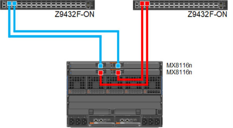
Figure 5. 100 GbE Single Fabric
Dual fabric combined fabrics
In this option, four MX8116n (2x in Fabric A and 2x in Fabric B) can be installed and combined to connect Z9432F-ON external FSE.
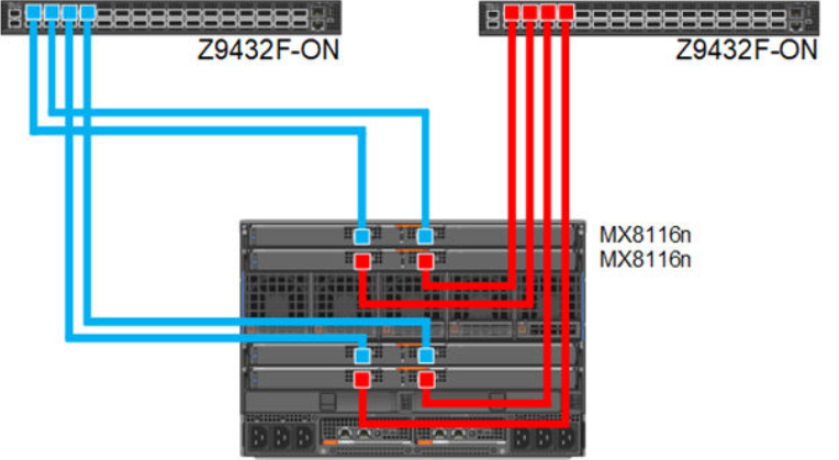
Figure 6. 100 GbE Dual Fabric combined Fabrics
Dual fabric separate fabrics
In this option four, MX8116n (2x in Fabric A and 2x in Fabric B) can be installed and connected to two different networks. In this case, the MX760c server module has two mezzanine cards, with each card connected to a separate network.
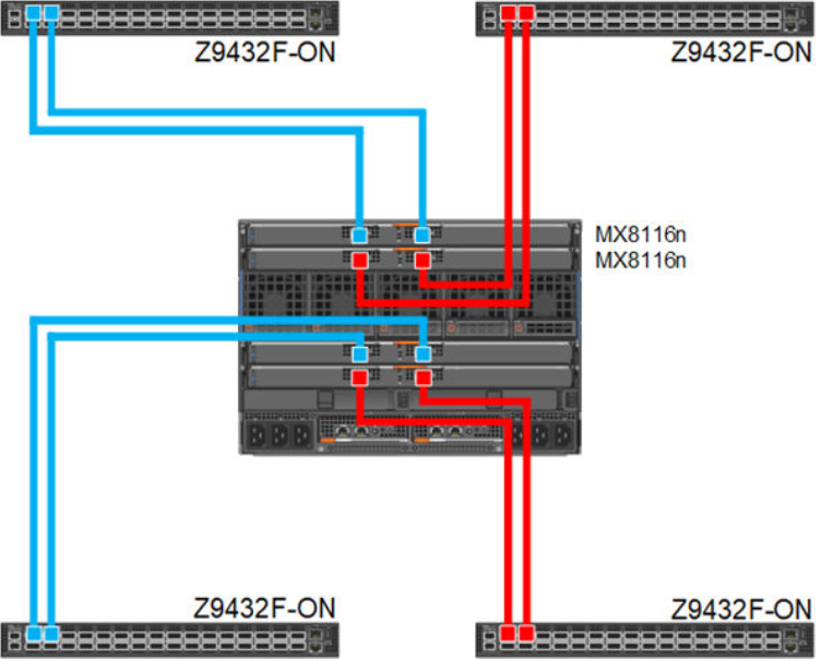
Figure 7. 100 GbE Dual Fabric separate Fabrics
Dual fabric, single MX8116n in each fabric, separate fabrics
In this option two, MX8116n (1x in Fabric A and 1x in Fabric B) can be installed and connected to two different networks. In this case, the MX760c server module has two mezzanine cards, each connected to a separate network.
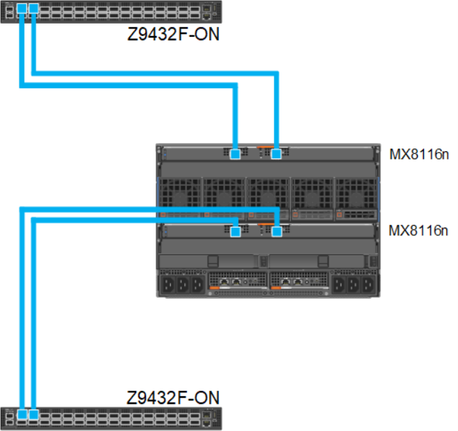
Figure 8. 100 GbE Dual Fabric single FEM in separate Fabrics
References
Dell PowerEdge Networking Deployment Guide
A chapter about 100 GbE solution with external Fabric Switching Engine