


Announcing Drain-based Nondisruptive Upgrades (NDUs)
Thu, 16 Sep 2021 17:43:39 -0000
|Read Time: 0 minutes
During an NDU workflow, nodes are rebooted or the protocol service must be stopped temporarily. Up until now, this has required a disruption for the clients who are connected to the rebooting node.
A drain-based NDU provides a mechanism by which nodes are prevented from rebooting or restarting protocol services until all SMB clients have disconnected from the node. Because a single SMB client that does not disconnect can cause the upgrade to be delayed indefinitely, the user is now provided with options to reboot the node despite persisting clients.
A drain-based upgrade supports the following scenarios and is available for WebUI, CLI, and PAPI:
- SMB protocol
- OneFS upgrades
- Firmware upgrades
- Cluster reboots
- Combined upgrades (OneFS and firmware)
A drain-based upgrade is built upon a parallel upgrade workflow, introduced in OneFS 8.2.2.0, that offers parallel node upgrade and reboot activity across node neighborhoods. It upgrades at most one node per neighborhood at any time. By doing that, it can shorten upgrade time and ensure that the end-user can continue to have access to their data. The more node neighborhoods within a cluster, the more parallel activity can occur.
Figure 1 shows how it works. In this example, there are two neighborhoods in a 6-node PowerScale cluster. Nodes 1 thru 3 belong to Neighborhood 1; Nodes 4 thru 6 belong to Neighborhood 2.
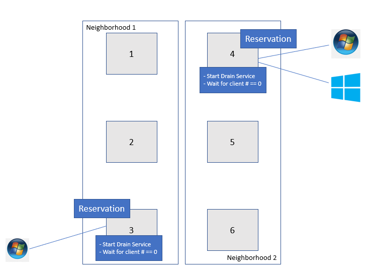
Figure 1: An example of Drain based NDU
You can use the following command to identify the correlation between your PowerScale nodes and neighborhoods (failure domains):
# sysctl efs.lin.lock.initiator.coordinator_weights
Once the drain-based upgrade is started, at most one node from each neighborhood will get the reservation that allows the nodes to upgrade simultaneously. OneFS will not reboot these nodes until the number of SMB clients is “0”. In this example, Node 3 and Node 4 get the reservation for upgrading at the same time. However, there is one SMB connection for Node 3 and two SMB connections for Node 4. They will not be able to reboot until the SMB connections get to “0”. At this stage, there are three options:
- Wait - Wait until the number of SMB connections reaches “0” or it hits the drain timeout value. The drain timeout value is the configurable parameter for each upgrade process. It is the maximum waiting period. If drain timeout is set to “0”, it means wait forever.
- Delay drain - Add the node to the delay list to delay client draining. The upgrade process will continue on another node in this neighborhood. After all the non-delayed nodes are upgraded, OneFS will return to the node in the delay list.
- Skip drain - Stop waiting for clients to migrate away from the draining node and reboot immediately.
To run the drain-based NDU, follow these steps:
1. In the OneFS CLI, run the following command to perform the drain-based upgrade. In this example, we have set the drain timeout value to 60 minutes and the alert timeout value to 45 minutes. This means if there is still some connection after 45 minutes, a CELOG notification will be triggered to the administrator.
# isi upgrade start --parallel --skip-optional --install-image-path=/ifs /data/<installation-file-name> --drain-timeout=60m --alert-timeout=45m
The draining service is now waiting for further action (wait, delay, or skip) from the end user, when it detects that there is an active SMB connection between client and PowerScale.
2. In the OneFS WebUI, navigate to Upgrade under Cluster management. In this window you will see the node waiting for draining clients. You can either specify Skip or Delay. In this case, Skip is selected as shown in Figure 2. In the prompt window, click the Skip button to skip draining.
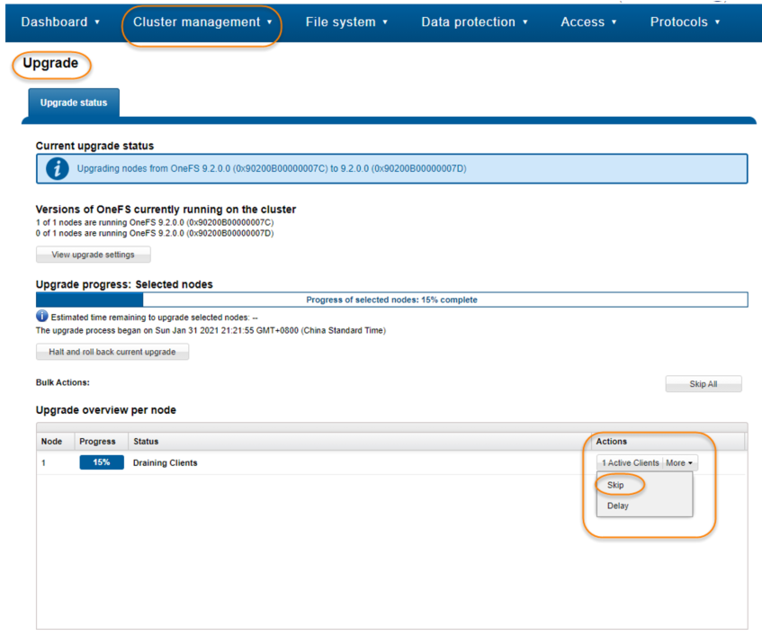
Figure 2. Skip the draining clients
Conclusion
Drain-based NDU can minimize the business impact during the OneFS upgrade process by allowing you to control how and when clients disconnect from the PowerScale cluster. This new feature can significantly improve the user experience and business continuity.
Author: Vincent Shen
Related Blog Posts

Backing Up and Restoring PowerScale Cluster Configurations in OneFS 9.7
Wed, 13 Dec 2023 14:00:00 -0000
|Read Time: 0 minutes
Backing up and restoring OneFS cluster configurations is not new, as it was introduced in OneFS 9.2. However, only a limited set of components can be backed up or restored. This is a popular feature and we have received a lot of feedback that we should add more supported components. Now, with the release of OneFS 9.7, this feature gets a big enhancement. The following is a complete list of the components we support in 9.7. (The new ones are marked in blue.)
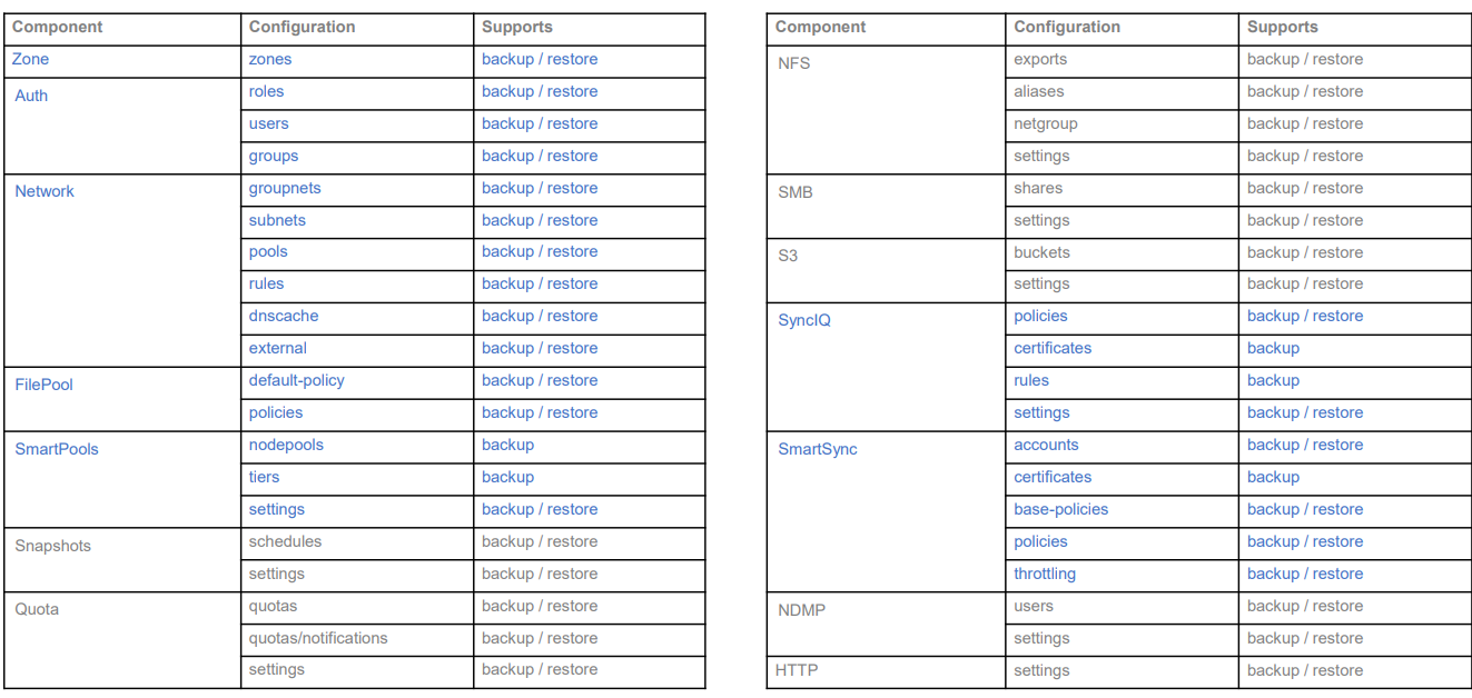
Some other enhancements include:
- Lock configuration during backup
- Support custom rules for restoring subnet IP addresses
Next, I’ll walk you through an example and explain the details of these enhancements.
Let’s take a look at the backup first.
Like what we have in the previous version, backup and restore are only available through PAPI and CLI (there is no WebUI at this stage). But I can guarantee you that the overall process is very simple and straightforward. If you are familiar with how to do it in the previous version, it’s almost the same.
You can use the following CLI command to back up a cluster configuration:
isi cluster config exports create [--components …]
Here is an example where I want to export the network configuration:
# isi cluster config exports create –components=Network
The following components’ configuration are going to be exported:
[‘Network’]
Notice:
    The exported configuration will be saved in plain text. It is recommended to encrypt it according to your specific requirements.
Do you want to continue? (yes/[no]): yes
This may take a few seconds, please wait a moment
Created export task ‘vshen-0eis0wn-20231128032252’
You can see that once the backup is triggered, a task is automatically created, and you can use the following command to view the details of the task:
isi cluster config exports view <export-id>
Here is what I have in my environment:
# isi cluster config exports view –id vshen-0eis0wn-20231128032252
     ID: vshen-0eis0wn-20231128032252
 Status: Successful
   Done: [‘network’]
 Failed: []
Pending: []
Message:
   Path: /ifs/data/Isilon_Support/config_mgr/backup/vshen-0eis0wn-20231128032252
During backup, to make a consistent configuration, a temporary lock is enabled to prevent new PAPI calls like POST, PUT, and DELETE. (The GET method will not be impacted.) In most cases, the backup job is completed quickly and it releases the lock when it finishes running.
You can use the following command to view the backup lock:
# isi cluster config lock view
Configuration lock enabled: Yes
You can also use the CLI command to manually enable or disable the lock:
# isi cluster config lock modify –action=enable
WARNING: User won’t be able to make any configuration changes after enabling configuration lock.
Are you sure you want to enable configuration lock? (yes/[no]): yes
After the backup task completes, the backup files will be generated under: /ifs/data/Isilon_Support/config_mgr/backup. Although the backup files are in plain text format, the sensitive information doesn’t appear here.
cat ./network_vshen-0eis0wn-20231128032252.json
{
  "description": {
    "component": "network",
    "release": "9.7.0.0",
    "action": "backup",
    "job_id": "vshen-0eis0wn-20231128032252",
    "result": "successful",
    "errors": []
  },
  "network": {
    "dnscache": {
      "cache_entry_limit": 65536,
       "cluster_timeout": 5,
       "dns_timeout": 5,
       "eager_refresh": 0,
       "testping_delta": 30,
       "ttl_max_noerror": 3600,
       "ttl_max_nxdomain": 3600,
…
When doing an import, you can use a command similar to the following:
# isi cluster config imports create --export-id=vshen-0eis0wn-20231128032252
Source Cluster Information:
          Cluster name: vshen-0eis0wn
       Cluster version: 9.7.0.0
            Node count: 1
  Restoring components: ['network']
Notice:
    Please review above information and make sure the target cluster has the same hardware configuration as the source cluster, otherwise the restore may fail due to hardware incompatibility. Please DO NOT use or change the cluster while configurations are being restored. Concurrent modifications are not guaranteed to be retained and some data services may be affected.
Do you want to continue? (yes/[no]): yes
This may take a few seconds, please wait a moment
Created import task 'vshen-0eis0wn-20231128064821'
When you deal with network component restore, to avoid connectivity breaks you can restore the configuration without destroying any existing subnets or pools’ IP addresses.
To do this, use the parameter “--network-subnets-ip”:
# isi cluster config imports create --export-id=vshen-0eis0wn-20231128032252 --network-subnets-ip="groupnet0.subnet0:10.242.114.0/24"
Source Cluster Information:
          Cluster name: vshen-0eis0wn
       Cluster version: 9.7.0.0
            Node count: 1
  Restoring components: ['network']
Notice:
    Please review above information and make sure the target cluster has the same hardware configuration as the source cluster, otherwise the restore may fail due to hardware incompatibility. Please DO NOT use or change the cluster while configurations are being restored. Concurrent modifications are not guaranteed to be retained and some data services may be affected.
Do you want to continue? (yes/[no]): yes
This may take a few seconds, please wait a moment
Created import task 'vshen-0eis0wn-20231128070157'
That’s how it works! As I said, it’s very simple and straightforward. If you see any errors, you can check the log: /var/log/config_mgr.log.
Author: Vincent Shen

Alert in IIQ 5.0.0 – Part I
Wed, 13 Dec 2023 17:40:06 -0000
|Read Time: 0 minutes
Alert is a new feature introduced with the release of IIQ 5.0.0. It provides the capability and flexibility to configure alerts based on the KPI threshold.
This blog will walk you through the following aspects of this feature:
- Introduction to Alert
- How to configure alerts using Alert
Let’s get started:
Introduction
IIQ 5.0.0 can send email alerts based on your defined KPI and threshold. The supported KPIs are listed in the following table:
KPI Name | Description | Scope |
Protocol Latency SMB | Average latency within last 10 minutes required for the various operations for the SMB protocol | Across all nodes and clients per cluster. |
Protocol Latency NFS | Average latency within last 10 minutes required for the various operations for the NFS protocol. | Across all nodes and clients per cluster. |
Active Clients NFS | The current number of active clients using NFS. The client is active when it is transmitting or receiving data. | Across all nodes per cluster. |
Active Clients SMB 1 | The current number of active clients using SMB 1. The client is active when it is transmitting or receiving data. | Across all nodes per cluster. |
Active Clients SMB 2 | The current number of active clients using SMB 2. The client is active when it is transmitting or receiving data. | Across all nodes per cluster. |
Connected Clients NFS | The current number of connected clients using NFS. The client is connected when it has an open TCP connection to the cluster. It can transmit or receive data or it can be in an idle state. | Across all nodes per cluster. |
Connected Clients SMB | The current number of connected clients using SMB. The client is connected when it has an open TCP connection to the cluster. It can transmit or receive data or it can be in an idle state. | Across all nodes per cluster. |
Pending Disk Operation Count | The average pending disk operation count within the last 10 minutes. It is the number of I/O operations that are pending at the file system level and waiting to be issued to an individual drive. | Across all disks per cluster. |
CPU Usage | The average usage of CPU cores including the physical cores and hyperthreaded core within last 10 minutes. | Across all nodes per cluster. |
Cluster Capacity | The current used capacity for the cluster. | N/A |
Nodepool Capacity | The current used capacity for the node pool in a cluster. | N/A |
Drive Capacity | The current used capacity for a drive in a cluster. | N/A |
Node Capacity | The current used capacity for a node in a cluster. | N/A |
Network Throughput Equivalency | Checks whether the network throughput for each node within the last 10 minutes is within the specified threshold percentage of the average network throughput of all nodes in the node pool for the same time. | Across all nodes per node pool. |
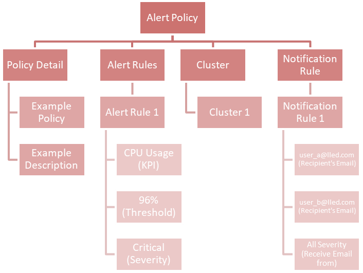
Each KPI requires a threshold and a severity level, together forming an alert rule. You can customize the alert rules to align with specific business use cases.
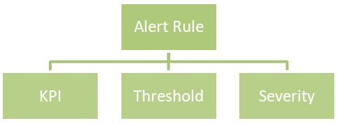
Here is an example of an alert rule:
If CPU usage (KPI) is greater than or equal to 96% (threshold), a critical alert (severity) will be triggered.
The supported severities are:
- Emergency
- Critical
- Warning
- Information
You can combine multiple alert rules into a single alert policy for easy management purposes.
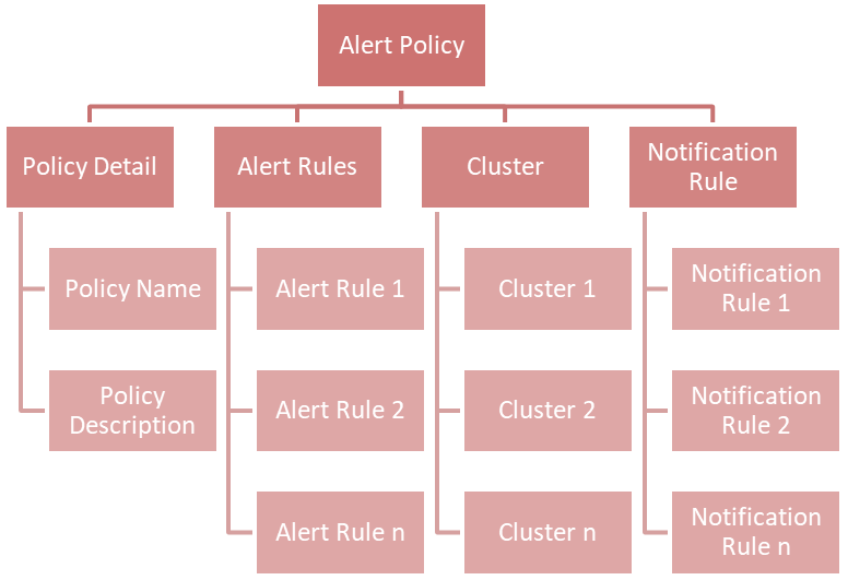
If you take a look at the chart above, you will find a new concept called Notification Rule. This is used to define the recipients' Email address and from what severity they will receive an Email:
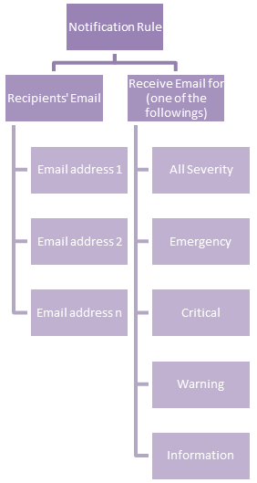
An example of a notification rule is like this: for user A (user_a@lled.com) and user B (user_b@lled.com), they both will receive Email alerts from all severity.
If you combine the above two examples and put them into the view of alert policy, you will get:
At this point, you should understand the big picture of the alert feature in IIQ 5.0.0. In my next post, I will walk you through the details of how to configure it.