


Amazon EKS Connector with EKS Anywhere on Dell PowerFlex
Tue, 17 Jan 2023 06:19:04 -0000
|Read Time: 0 minutes
Why Amazon EKS Anywhere?
Digital transformation and application modernization have taken to new heights in the recent past. As businesses transform digitally, a demand for adopting modern infrastructure has equally grown to run applications at scale and provide fault-tolerant infrastructure.
With an ever-evolving technology landscape, it becomes important for industries to be well-positioned and equipped with the tools and capabilities to scale as the business grows.
Kubernetes is an effective containerization platform when it comes to running microservices and modern applications. Kubernetes is available with every major cloud provider as a service and can also be deployed in private cloud environments.
Amazon Elastic Kubernetes Service (EKS) Anywhere has taken the containerized platform to new heights. Amazon EKS Anywhere allows organizations to run an Amazon EKS cluster anywhere including in an on-premises private cloud.
What is Amazon EKS Connector?
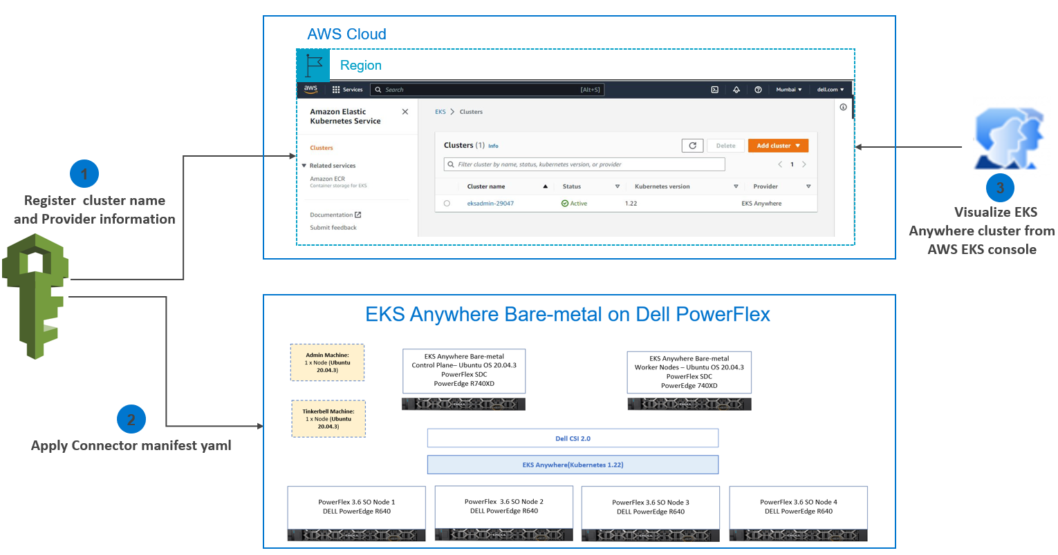
In this blog, we will discuss the Amazon EKS connector that enables you to leverage Amazon EKS Console to view the entire Kubernetes infrastructure from a single pane of glass. Amazon EKS Anywhere and Amazon EKS Connector are strategically the best fit for businesses embracing hybrid cloud environments and private infrastructure setups.
Amazon EKS Connector is a new capability that allows administrators to securely connect any Kubernetes cluster (not limited to EKS Anywhere) to the EKS Console and provides a unified view of the entire Kubernetes environment.
Connecting your on-premises Kubernetes cluster with the EKS Console requires you to register the cluster with EKS and run the EKS Connector agent on the external Kubernetes cluster. EKS Connector agent installed on the connected cluster establishes a secured communication channel using a session manager.
There are multiple ways to register a Kubernetes cluster running anywhere with the AWS EKS console. You can use AWS CLI, eksctl, SDK or console. When registering with the eksctl or console option, a YAML manifest file is auto-populated with the required parameters and settings. However, some additional manual steps are required.
Note: Registering the Kubernetes cluster with the EKS console requires that you create the following IAM roles and groups in AWS IAM to be able to perform the required operations:
- Service-linked role for Amazon EKS
- EKS-Connector-Agent Role
Once the connection process is complete, administrators can use the Amazon EKS Console to view all connected clusters and their associated resources.
 Amazon EKS Connector
Connecting a Kubernetes Cluster running on the Dell PowerFlex cluster to the EKS Console
Let us dig a little deeper into connecting a Kubernetes Cluster running on the Dell PowerFlex cluster to the EKS Console.
The cluster registration process involves two steps:
1. Register the cluster with Amazon EKS
2. Apply a connector YAML manifest file in the target cluster to enable connectivity.
Step 1: Register the cluster with Amazon EKS
EKS console includes a register option along with the create cluster option. Open the EKS console and go to the Clusters section. From Add cluster select the Register option as shown in the following image:
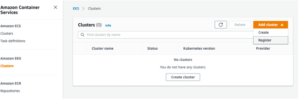 Registering the EKS Connector
- Enter the following details in the cluster registration form:
- Define a name for your cluster.
- Select the provider as EKS Anywhere (which is the case in this example).
- Select the EKS Connector Role that you created to enable the Kubernetes control plane to create resources on your behalf.
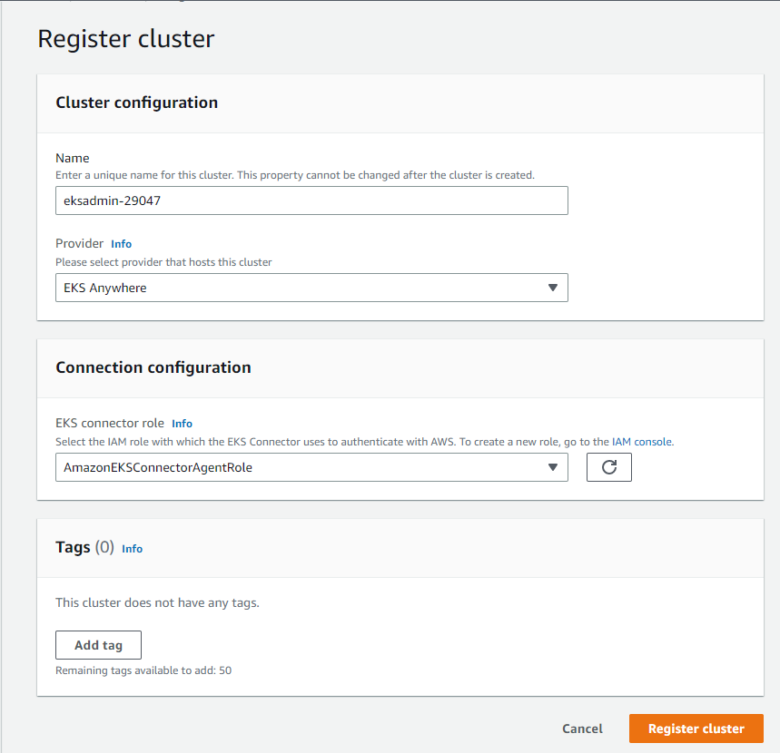 Cluster registration
- Click Register cluster.
- After the cluster is added the Cluster name is displayed and the status shows Active as shown in the following figure:
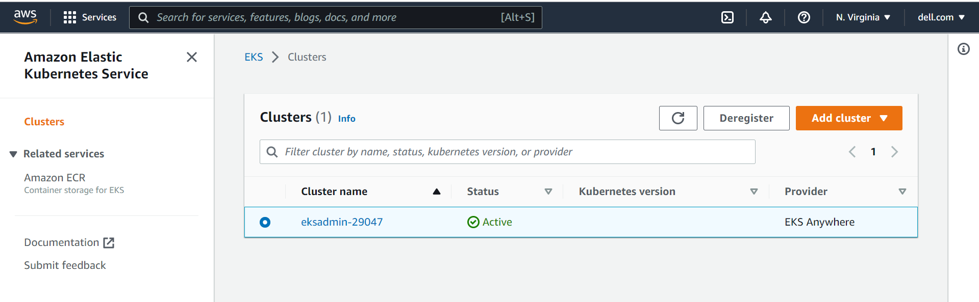 Cluster status
Step 2: Apply a connector YAML manifest file in the target cluster to enable connectivity
- After registering the cluster, you will be redirected to the Cluster Overview page. Click Download YAML file and install the file on your Kubernetes cluster to connect to the EKS console as shown in the following figure:
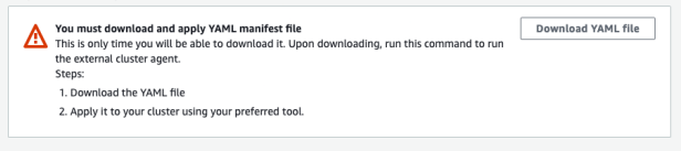 Cluster overview
- Apply downloaded eks-connector.yaml as follows:
kubectl apply -f eks-connector.yaml |
The EKS Connector runs in StatefulSet mode on your Kubernetes cluster. The connector establishes a connection and proxies the communication between the API server of your EKS Anywhere cluster and Amazon Web Services. The connector is used to display cluster data in the Amazon EKS console until you disconnect the cluster from AWS.
The YAML manifest file generated during the cluster registration process creates the following containers:
InitContainer: This container registers the EKS Connector agent with the Systems Manager control plane service and populates the registration information in the Kubernetes backend data store. InitContainer mounts this data to the EKS Connector agent’s volume when it is recycled. This eliminates the need of registration whenever a pod is recycled.
EKS Connector agent: This is an agent based on the SSM agent, running in container mode. This agent creates an outbound connection from the Kubernetes cluster to the AWS network. All subsequent requests from AWS are performed using the connection channels established by the EKS Connector agent.
Connector proxy: This agent acts as a proxy between the EKS Connector agent and Kubernetes API Server. This proxy agent uses the Kubernetes service account to impersonate the IAM user that accesses the console and fetches information from the Kubernetes API Server.
As one can see the EKS connector agent liaisons with the SSM service, which in turn interacts with the EKS service via EventBridge. To facilitate the interaction, the EKS connector agent role is required with appropriate permissions to create, open, and control the SSM channels. In the absence, of this important IAM role at AWS end, the creation and control of Systems Manager channels would not be possible eventually leading to an unsuccessful registration
Upon successful registration, one can notice the changes in the AWS EventBridge services. A new event rule with the pattern of registration and deregistration is created under the “default” event bus.
eks-connector-console-dashboard-full-access-group: This is a YAML manifest consisting of roles and bindings that are required to get access to all namespaces and resources to be visualized in the console.
Download and apply the eks-connector-console-dashboard-full-access. YAML as follows:
curl -o eks-connector-console-dashboard-full-access-group.yaml https://s3.us-west-2.amazonaws.com/amazon-eks/eks-connector/manifests/eks-connector-console-roles/eks-connector-console-dashboard-full-access-group.yaml
kubectl apply -f eks-connector-console-dashboard-full-access.yaml
eks-connector-clusterrole: This is a YAML manifest consisting of cluster roles and bindings for the cluster to define permissions on namespaces and cluster scope resources.
Download the apply eks-connector-cluster-role as follows:
curl -o eks-connector-clusterrole.yaml https://s3.us-west-2.amazonaws.com/amazon-eks/eks-connector/manifests/eks-connector-console-roles/eks-connector-clusterrole.yaml
kubectl apply -f eks-connector-clusterrole.yaml
Amazon EKS Console
The Overview section shows all the cluster resources. All the objects are read-only, and the user cannot edit or delete an object in the registered cluster as shown in the following figure:
 Dashboard
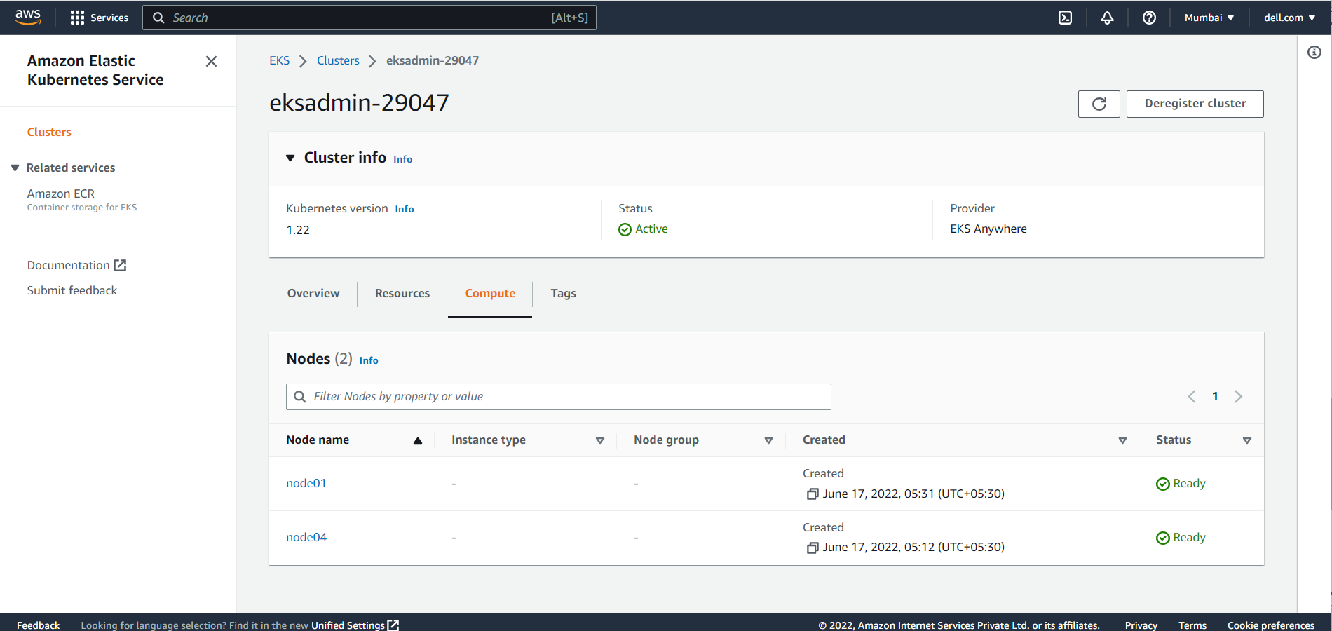
The Compute section shows all the Dell PowerFlex node resources in the Amazon EKS Anywhere Cluster.
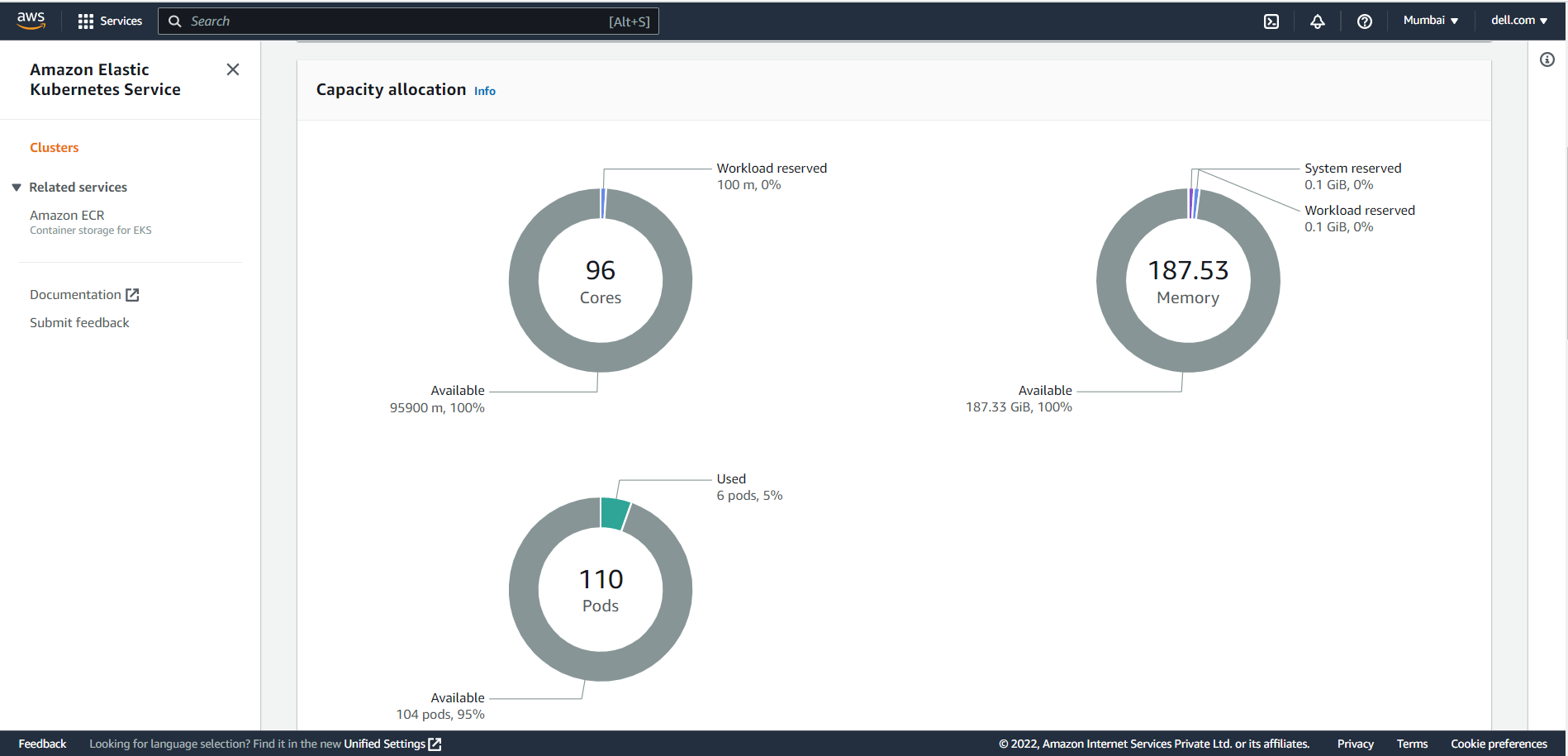 Compute
The Workloads section displays all objects of Type: Deployment, DaemonSet and StatefulSet. Users can select these objects to select a pod-level overview.
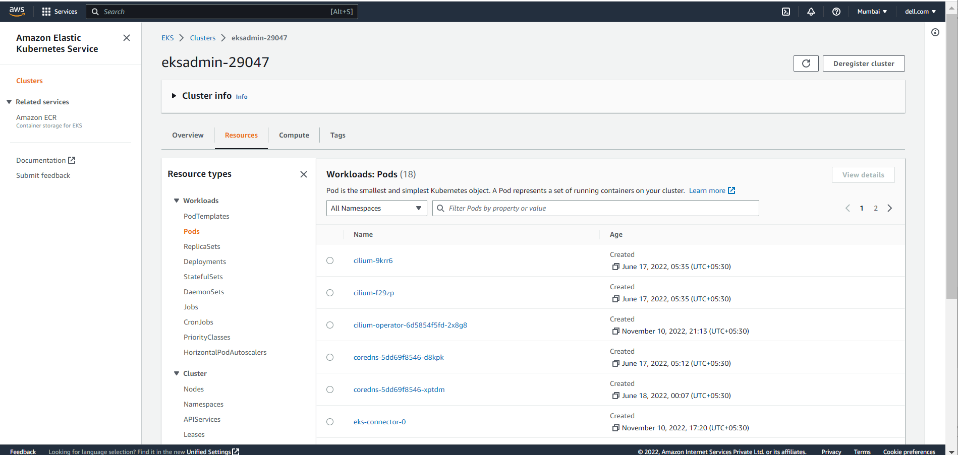 Workloads
Conclusion
In this blog, we have explored the Amazon EKS Connector, and how to connect and register the Kubernetes cluster to the Amazon console. Using the Amazon EKS Connector, organizations can now leverage Amazon EKS Console to bring together both the cloud environment and private infrastructure setups and view them from a single pane of glass.
If you are interested to find out more about how to use Amazon EKS Anywhere and the Amazon EKS Connector in the PowerFlex environment, reach out to your Dell representative.
Resources
- Amazon Elastic Kubernetes Service Anywhere on Dell PowerFlex
- Introducing bare metal deployments for Amazon EKS Anywhere
- Customer Choice Comes First: Dell Technologies and AWS EKS Anywhere
Related Blog Posts

Q1 2024 Update for Ansible Integrations with Dell Infrastructure

Tue, 02 Apr 2024 14:45:56 -0000
|Read Time: 0 minutes
In this blog post, I am going to cover the new Ansible functionality for the Dell infrastructure portfolio that we released over the past two quarters. Ansible collections are now on a monthly release cadence, and you can bookmark the changelog pages from their respective GitHub pages to get updates as soon as they are available!
PowerScale Ansible collections 2.3 & 2.4
SyncIQ replication workflow support
SyncIQ is the native remote replication engine of PowerScale. Before seeing what is new in the Ansible tasks for SyncIQ, let’s take a look at the existing modules:
- SyncIQPolicy: Used to query, create, and modify replication policies, as well as to start a replication job.
- SyncIQJobs: Used to query, pause, resume, or cancel a replication job. Note that new synciq jobs are started using the synciqpolicy module.
- SyncIQRules: Used to manage the replication performance rules that can be accessed as follows on the OneFS UI:
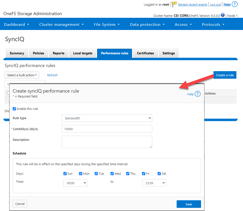
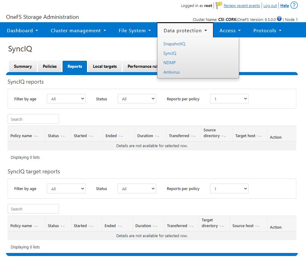
- SyncIQReports and SyncIQTargetReports: Used to manage SyncIQ reports. Following is the corresponding management UI screen where it is done manually:
Following are the new modules introduced to enhance the Ansible automation of SyncIQ workflows:
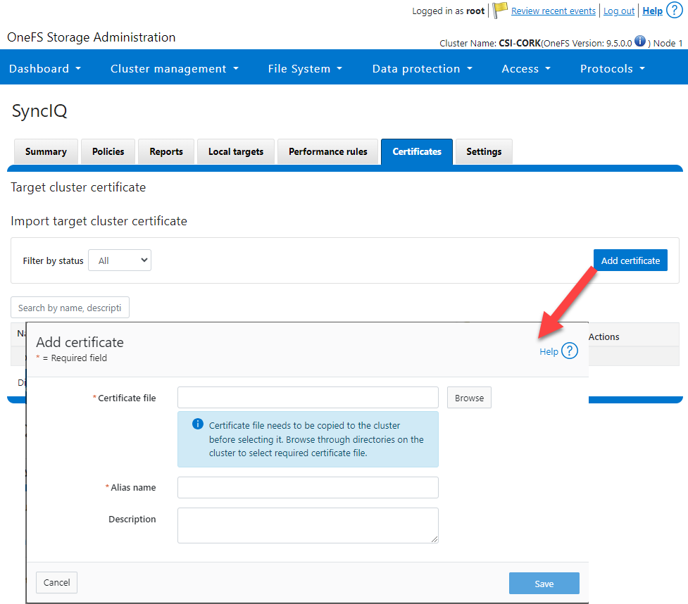
- SyncIQCertificate (v2.3): Used to manage SyncIQ target cluster certificates on PowerScale. Functionality includes getting, importing, modifying, and deleting target cluster certificates. Here is the OneFS UI for these settings:
- SyncIQ_global_settings (v2.3): Used to configure SyncIQ global settings that are part of the include the following:
Table 1. SyncIQ settings
SyncIQ Setting (datatype) | Description |
bandwidth_reservation_reserve_absolute (int) | The absolute bandwidth reservation for SyncIQ |
bandwidth_reservation_reserve_percentage (int) | The percentage-based bandwidth reservation for SyncIQ |
cluster_certificate_id (str) | The ID of the cluster certificate used for SyncIQ |
encryption_cipher_list (str) | The list of encryption ciphers used for SyncIQ |
encryption_required (bool) | Whether encryption is required or not for SyncIQ |
force_interface (bool) | Whether the force interface is enabled or not for SyncIQ |
max_concurrent_jobs (int) | The maximum number of concurrent jobs for SyncIQ |
ocsp_address (str) | The address of the OCSP server used for SyncIQ certificate validation |
ocsp_issuer_certificate_id (str) | The ID of the issuer certificate used for OCSP validation in SyncIQ |
preferred_rpo_alert (bool) | Whether the preferred RPO alert is enabled or not for SyncIQ |
renegotiation_period (int) | The renegotiation period in seconds for SyncIQ |
report_email (str) | The email address to which SyncIQ reports are sent |
report_max_age (int) | The maximum age in days of reports that are retained by SyncIQ |
report_max_count (int) | The maximum number of reports that are retained by SyncIQ |
restrict_target_network (bool) | Whether to restrict the target network in SyncIQ |
rpo_alerts (bool) | Whether RPO alerts are enabled or not in SyncIQ |
service (str) | Specifies whether the SyncIQ service is currently on, off, or paused |
service_history_max_age (int) | The maximum age in days of service history that is retained by SyncIQ |
service_history_max_count (int) | The maximum number of service history records that are retained by SyncIQ |
source_network (str) | The source network used by SyncIQ |
tw_chkpt_interval (int) | The interval between checkpoints in seconds in SyncIQ |
use_workers_per_node (bool) | Whether to use workers per node in SyncIQ or not |
Additions to Info module
The following information fields have been added to the Info module:
- S3 buckets
- SMB global settings
- Detailed network interfaces
- NTP servers
- Email settings
- Cluster identity (also available in the Settings module)
- Cluster owner (also available in the Settings module)
- SNMP settings
- SynciqGlobalSettings
PowerStore Ansible collections 3.1: More NAS configuration
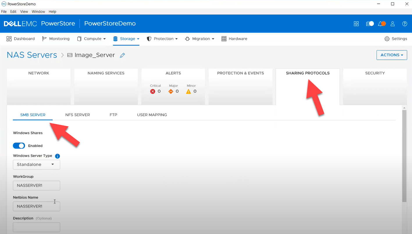
In this release of Ansible collections for PowerStore, new modules have been added to manage the NAS Server protocols like NFS and SMB, as well as to configure a DNS or NIS service running on PowerStore NAS.
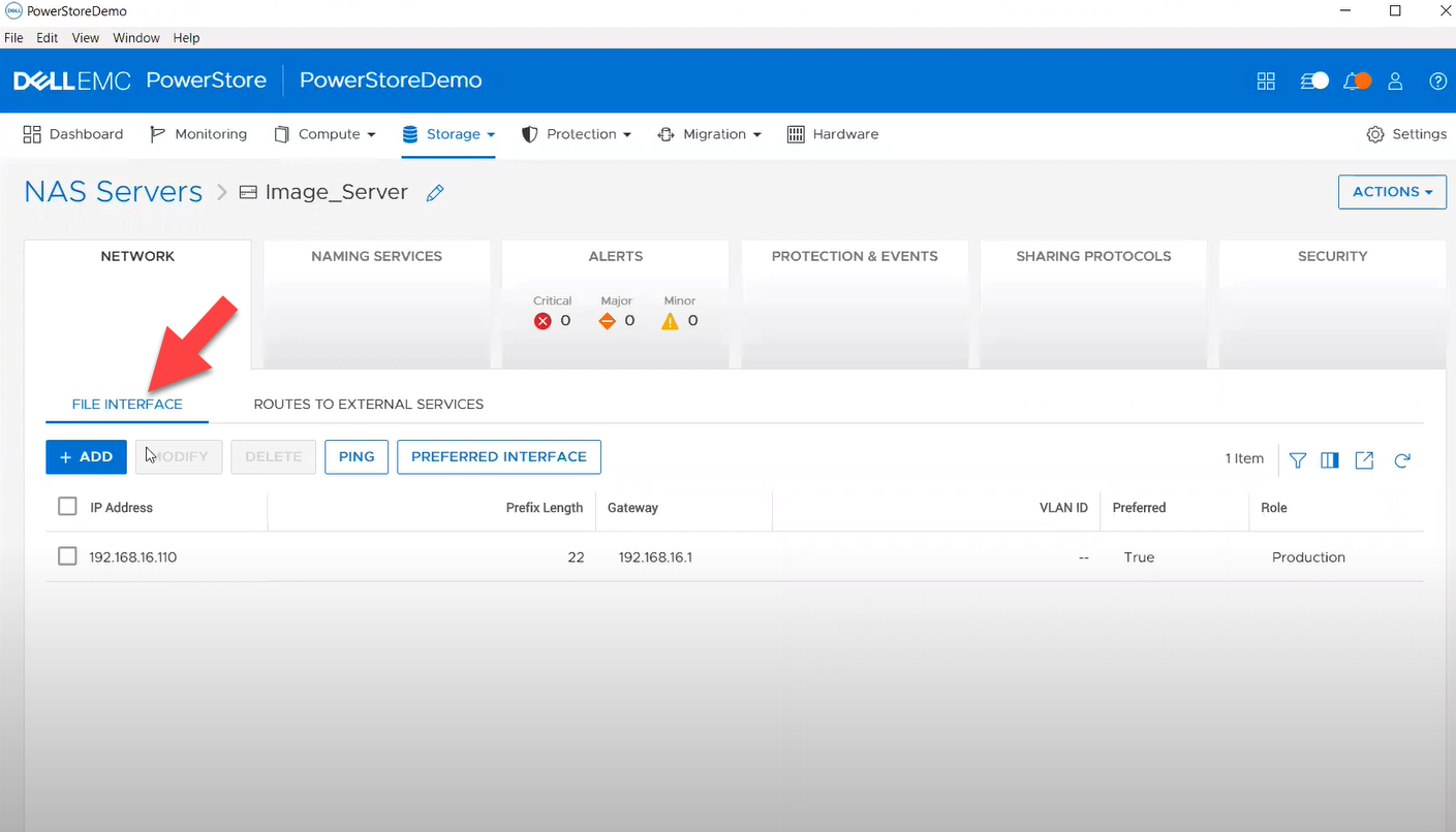
Managing NAS Server interfaces on PowerStore
- file_interface - to enable, query, and modify PowerStore NAS interfaces. Some examples can be found here.
- smb_server - to enable, query, and modify SMB Shares on PowerStore NAS. Some examples can be found here.
- nfs_server - to enable, query, and modify NFS Server on PowerStore NAS. Some examples can be found here.
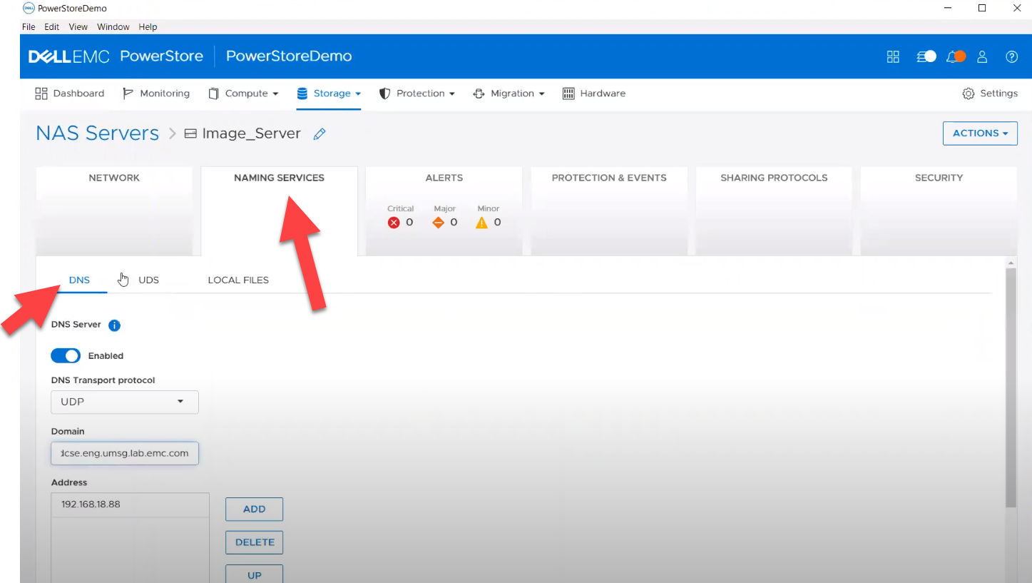
Naming services on PowerStore NAS
- file_dns – to enable, query, and modify File DNS on PowerStore NAS. Some examples can be found here.
- file_nis - to enable, query, and modify NIS on PowerStore NAS. Some examples can be found here.
- service_config - manage service config for PowerStore
The Info module is enhanced to list file interfaces, DNS Server, NIS Server, SMB Shares, and NFS exports. Also in this release, support has been added for creating multiple NFS exports with same name but different NAS servers.
PowerFlex Ansible collections 2.0.1 and 2.1: More roles
In releases 1.8 and 1.9 of the PowerFlex collections, new roles have been introduced to install and uninstall various software components of PowerFlex to enable day-1 deployment of a PowerFlex cluster. In the latest 2.0.1 and 2.1 releases, more updates have been made to roles, such as:
- Updated config role to support creation and deletion of protection domains, storage pools, and fault sets
- New role to support installation and uninstallation of Active MQ
- Enhanced SDC role to support installation on ESXi, Rocky Linux, and Windows OS
OpenManage Ansible collections: More power to iDRAC
At the risk of repetition, OpenManage Ansible collections have modules and roles for both OpenManage Enterprise as well as iDRAC/Redfish node interfaces. In the last five months, a plethora of a new functionalities (new modules and roles) have become available, especially for the iDRAC modules in the areas of security and user and license management. Following is a summary of the new features:
V9.1
- redfish_storage_volume now supports iDRAC8.
- dellemc_idrac_storage_module is deprecated and replaced with idrac_storage_volume.
v9.0
- Module idrac_diagnostics is added to run and export diagnostics on iDRAC.
- Role idrac_user is added to manage local users of iDRAC.
v8.7
- New module idrac_license to manage iDRAC licenses. With this module you can import, export, and delete licenses on iDRAC.
- idrac_gather_facts role enhanced to add storage controller details in the role output and provide support for secure boot.
v8.6
- Added support for the environment variables, `OME_USERNAME` and `OME_PASSWORD`, as fallback for credentials for all modules of iDRAC, OME, and Redfish.
- Enhanced both idrac_certificates module and role to support the import and export of `CUSTOMCERTIFICATE`, Added support for import operation of `HTTPS` certificate with the SSL key.
v8.5
- redfish_storage_volume module is enhanced to support reboot options and job tracking operation.
v8.4
- New module idrac_network_attributes to configure the port and partition network attributes on the network interface cards.
Conclusion
Ansible is the most extensively used automation platform for IT Operations, and Dell Technologies provides an exhaustive set of modules and roles to easily deploy and manage server and storage infrastructure on-prem as well as on Cloud. With the monthly release cadence for both storage and server modules, you can get access to our latest feature additions even faster. Enjoy coding your Dell infrastructure!
Author: Parasar Kodati, Engineering Technologist, Dell ISG

A Simple Poster at NVIDIA GTC – Running NVIDIA Riva on Red Hat OpenShift with Dell PowerFlex


Fri, 15 Mar 2024 21:45:09 -0000
|Read Time: 0 minutes
A few months back, Dell and NVIDIA released a validated design for running NVIDIA Riva on Red Hat OpenShift with Dell PowerFlex. A simple poster—nothing more, nothing less—yet it can unlock much more for your organization. This design shows the power of NVIDIA Riva and Dell PowerFlex to handle audio processing workloads.
What’s more, it will be showcased as part of the poster gallery at NVIDIA GTC this week in San Jose California. If you are at GTC, we strongly encourage you to join us during the Poster Reception from 4:00 to 6:00 PM. If you are unable to join us, you can view the poster online from the GTC website.
For those familiar with ASR, TTS, and NMT applications, you might be curious as to how we can synthesize these concepts into a simple poster. Read on to learn more.
NVIDIA Riva
For those not familiar with NVIDIA Riva, let’s start there.
NVIDIA Riva is an AI software development kit (SDK) for building conversational AI pipelines, enabling organizations to program AI into their speech and audio systems. It can be used as a smart assistant or even a note taker at your next meeting. Super cool, right?
Taking that up a notch, NVIDIA Riva lets you build fully customizable, real-time conversational AI pipelines, which is a fancy way of saying it allows you to process speech in a bunch of different ways including automatic speech recognition (ASR), text-to-speech (TTS), and neural machine translation (NMT) applications:
- Automatic speech recognition (ASR) – this is essentially dictation. Provide AI with a recording and get a transcript—a near perfect note keeper for your next meeting.
- Text-to-speech (TTS) – a computer reads what you type. In the past, this was often in a monotone voice. It’s been around for more than a couple of decades and has evolved rapidly with more fluid voices and emotion.
- Neural machine translation (NMT) – this is the translation of spoken language in near real-time to a different language. It is a fantastic tool for improving communication, which can go a long way in helping organizations extend business.
Each application is powerful in its own right, so think about what’s possible when we bring ASR, TTS, and NMT together, especially with an AI-backed system. Imagine having a technical support system that could triage support calls, sounded like you were talking to an actual support engineer, and could provide that support in multiple languages. In a word: ground-breaking.
NVIDIA Riva allows organizations to become more efficient in handling speech-based communications. When organizations become more efficient in one area, they can improve in other areas. This is why NVIDIA Riva is part of the NVIDIA AI Enterprise software platform, focusing on streamlining the development and deployment of production AI.
I make it all sound simple, however those creating large language models (LLMs) around multilingual speech and translation software know it’s not so. That’s why NVIDIA developed the Riva SDK.
The operating platform also plays a massive role in what can be done with workloads. Red Hat OpenShift enables AI speech recognition and inference with its robust container orchestration, microservices architecture, and strong security features. This allows workloads to scale to meet the needs of an organization. As the success of a project grows, so too must the project.
Why is Storage Important
You might be wondering how storage fits into all of this. That’s a great question. You’ll need high performance storage for NVIDIA Riva. After all, it’s designed to process and/or generate audio files and being able to do that in near real-time requires a highly performant, enterprise-grade storage system like Dell PowerFlex.
Additionally, AI workloads are becoming mainstream applications in the data center and should be able to run side by side with other mission critical workloads utilizing the same storage. I wrote about this in my Dell PowerFlex – For Business-Critical Workloads and AI blog.
At this point you might be curious how well NVIDIA Riva runs on Dell PowerFlex. That is what a majority of the poster is about.
ASR and TTS Performance
The Dell PowerFlex Solutions Engineering team did extensive testing using the LibriSpeech dev-clean dataset available from Open SLR. With this data set, they performed automatic speech recognition (ASR) testing using NVIDIA Riva. For each test, the stream was increased from 1 to 64, 128, 256, 384, and finally 512, as shown in the following graph.
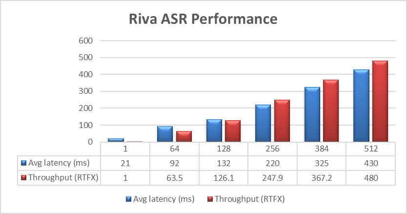 Figure 1. NVIDIA Riva ASR Performance
The objective of these tests is to have the lowest latency with the highest throughput. Throughput is measured in RTFX, or the duration of audio transcribed divided by computation time. During these tests, the GPU utilization was approximately 48% without any PowerFlex storage bottlenecks. These results are comparable to NVIDIA’s own findings in in the NVIDIA Riva User Guide.
The Dell PowerFlex Solutions Engineering team went beyond just looking at how fast NVIDIA Riva could transcribe text, also exploring the speed at which it could convert text to speech (TTS). They validated this as well. Starting with a single stream, for each run the stream is changed to 4, 6, 8, and 10, as shown in the following graph.
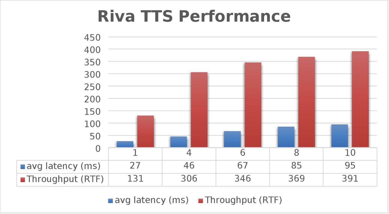 Figure 2. NVIDIA Riva TTS Performance
Again, the goal is to have a low average latency with a high throughput. The throughput (RTFX) in this case is the duration of audio generated divided by computation time. As we can see, this results in a RTFX throughput of 391 with a latency of 91ms with ten streams. It is also worth noting that during testing, GPU utilization was approximately 82% with no storage bottlenecks.
This is a lot of data to pack into one poster. Luckily, the Dell PowerFlex Solutions Engineering team created a validated architecture that details how all of these results were achieved and how an organization could replicate them if needed.
Now, to put all this into perspective, with PowerFlex you can achieve great results on both spoken language coming into your organization and converting text to speech. Pair this capability with some other generative AI (genAI) tools, like NVIDIA NeMo, and you can create some ingenious systems for your organization.
For example, if an ASR model is paired with a large language model (LLM) for a help desk, users could ask it questions verbally, and—once it found the answers—it could use TTS to provide them with support. Think of what that could mean for organizations.
It's amazing how a simple poster can hold so much information and so many possibilities. If you’re interested in learning more about the research Dell PowerFlex has done with NVIDIA Riva, visit the Poster Reception at NVIDIA GTC on Monday, March 18th from 4:00 to 6:00 PM. If you are unable to join us at the poster reception, the poster will be on display throughout NVIDIA GTC. If you are unable to attend GTC, check out the white paper, and reach out to your Dell representative for more information.
Authors: Tony Foster | Twitter: @wonder_nerd | LinkedIn
Praphul Krottapalli
Kailas Goliwadekar