
Memory interleaving
Memory interleaving
-
Memory interleaving allows a CPU to efficiently spread memory accesses across multiple DIMMs. When memory is put in the same interleave set, contiguous memory accesses go to different memory banks. Memory accesses no longer must wait until the prior access has completed before initiating the next memory operation. For most workloads, performance is maximized when all DIMMs are in one interleave set, creating a single uniform memory region that is spread across as many DIMMs as possible. Multiple interleave sets create disjointed memory regions.
4th Generation Intel® Xeon® Scalable Processors create interleave sets to efficiently spread memory accesses across memory controllers and channels, to increase memory data transfer speeds. The number of interleave sets created corresponds to how the memory modules populating each slot are configured. Preserving only one interleave set improves memory bandwidth by using all memory channels while any memory is accessed. As a result, the distribution of information is divided across several channels instead of just one, and the total memory bandwidth is increased. Generating any more than one interleave set creates additional work for the memory controllers, which reduces memory bandwidth. Therefore, the optimal memory subsystem design centers around generating only one interleave set.
Configuring memory to be balanced ensures that the number of required interleave sets is minimized: a total of one set. Anything beyond one interleave set is not fully balanced and is referred to as near balanced (partial fulfillment of balanced conditions) or as unbalanced (no fulfillment of balanced conditions) in this white paper.
As seen in the following figure, balanced memory configurations depend heavily upon properly configuring DIMMs/DCPMMs within the subsystem. The following figure shows 1 CPU configurations; for CPU2 configurations, populate respective DIMMs on CPU2 (B1-B16).
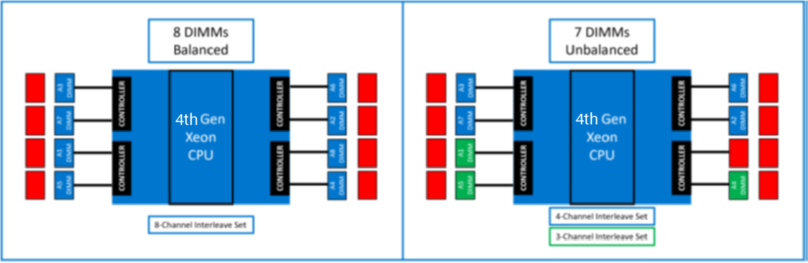
Figure 5. Side by side comparison of an unbalanced and balanced memory configuration.
The 7 DIMM unbalanced configuration has created two interleave sets due to non-symmetrical memory channel population, represented by blue and green colors. The IMC has essentially broken up memory into disjointed regions that degrade performance and create unpredictable process patterns. The 8 DIMM balanced configuration has symmetrical memory channel population across all memory channels, therefore creating only one interleave set and thus increasing memory bandwidth.