
Memory Population Rules for 3rd Generation Intel Xeon Scalable Processors on PowerEdge Servers
Memory topography and terminology
Memory topography and terminology
-
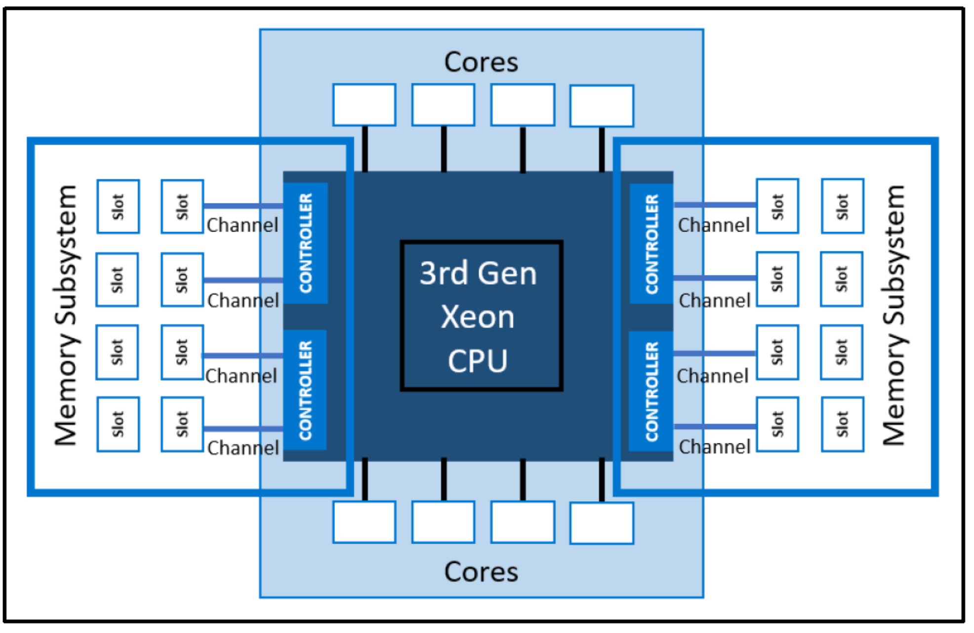
Figure 1. Overview of the CPU-to-memory subsystem connectivity
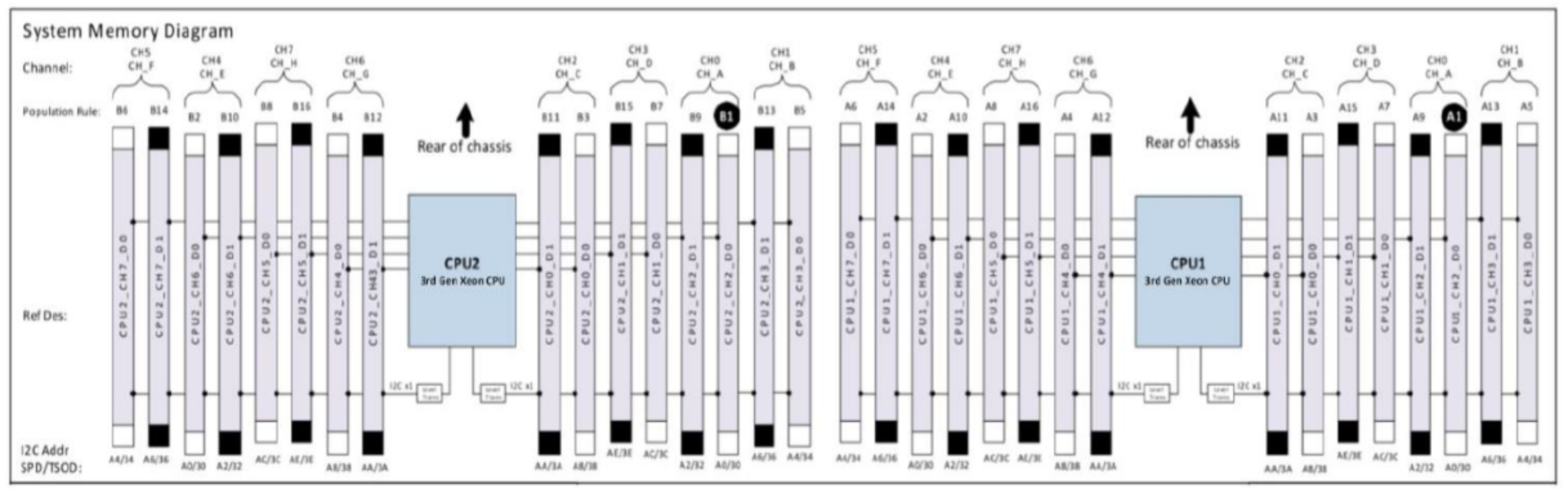
Figure 2. Decoding DIMM lettering/numbering to channel lettering/numbering
To understand the relationship between the CPU and memory, terminology illustrated in Figure 1 must first be addressed:
- Memory controllers are digital circuits that manage the flow of data going from the computer’s main memory to the corresponding memory channels. Each controller was intended to be populated with at least one DIMM. Xeon processors have four memory controllers.
- Memory channels are the physical layer on which the data travels between the CPU and memory modules. Channels were intended to be populated in a symmetrical fashion, so that when two channels horizontal of one another are populated an interleave set will be created. Xeon processors have eight memory channels.
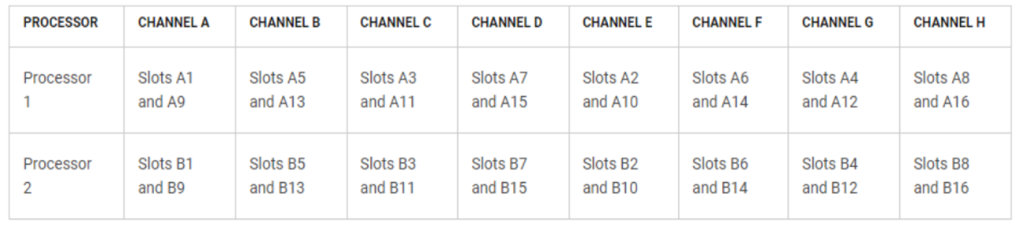
Figure 3. Memory channels
- Memory slots host individual memory modules, such as DIMMs or DCPMMs. Xeon processors have two slots per channel, so there are a total of sixteen slots per CPU for memory module population. As seen in Figure 2, for CPU1, DIMM 0 slots A1-A8 (the white slots) are the first eight memory modules to be populated, while DIMM 1 slots A9-A15 (the black ones) are the last eight to be populated. Similarly, for CPU2, DIMM 0 slots B1-B8 (the white slots) are the first eight memory modules to be populated, while DIMM 1 slots B9-B15 (the black ones) are the last eight to be populated. DIMM slot/channel numbering can also be referenced in Figure 3.
- The memory subsystem is the combination of all the independent memory functions listed above.