
SRDF/Non-Star
SRDF/Non-Star
-
SRDF supports a variety of 3-site solutions including Concurrent and Cascaded replication. These 3-site solutions always require a change to the EmcSrdfSraGlobalOptions.xml file to enable the parameter FailoverToAsyncSite.[3]
Concurrent SRDF
VMAX/PowerMax supports concurrent primary devices (R11) that are configured with two R1 SRDF mirrors. Two R1 SRDF mirrors allow the R11 devices to be mirrored concurrently to two R2 devices that can reside in one or two remote VMAX/PowerMax arrays. Each R1 SRDF mirror is configured to a different SRDF group.
Note: The R11 devices have to be assigned to two different SRDF groups even if the two partner R2 devices reside on the same remote VMAX/PowerMax array.
Concurrent SRDF topologies are supported on Fibre Channel, Gigabit Ethernet (GigE), and ESCON SRDF topologies.[4] Basic concurrent SRDF solutions require that each R1 SRDF mirror operate in the same primary mode, either both synchronous or both semi-synchronous, but allows either or both SRDF mirrors to be placed into one of the adaptive copy modes. Advanced concurrent SRDF solutions support one or both R1 SRDF mirrors of the R11 device operating in asynchronous mode.
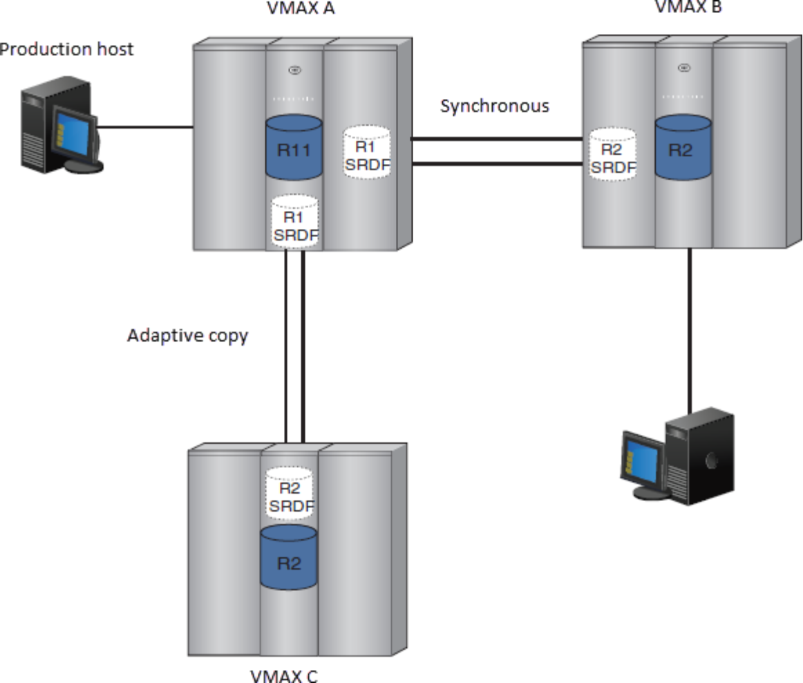
Figure 3 shows a concurrent VMAX SRDF topology in which the R11 device communicates with the R2 device in VMAX B in synchronous mode. Concurrently, the same R11 device communicates with the R2 device in VMAX C in one of the adaptive copy modes. The R1s are shown separately as pairs in VMAX A for clarity, but it is the same device.
Concurrent SRDF supports the following topologies:
- Both legs are replicating in Synchronous mode
- Both legs are replicating in Asynchronous mode
- One leg is Asynchronous and the other leg is Synchronous
- One leg is Active and the other leg is Asynchronous
- Adaptive Copy is also supported in place of either Asynchronous or Synchronous.
Note: Not all revisions of HYPERMAX OS/PowerMaxOS support all topologies. Please refer to the SRDF Product Guide for specific restrictions.
Figure 3. Concurrent SRDF example
Cascaded SRDF
Cascaded SRDF is a 3-site disaster recovery solution where data from a primary (R1) site is synchronously mirrored to a secondary (R21) site, and then asynchronously mirrored from the secondary (R21) site to a tertiary (R2) site. The core benefit behind a cascaded topology is its inherent capability to continue mirroring, with minimal user intervention, from the secondary site to the tertiary site in the event that the primary site fails. This enables a faster recovery at the tertiary site, assuming that the tertiary site is where the customer wants to restart production operations.
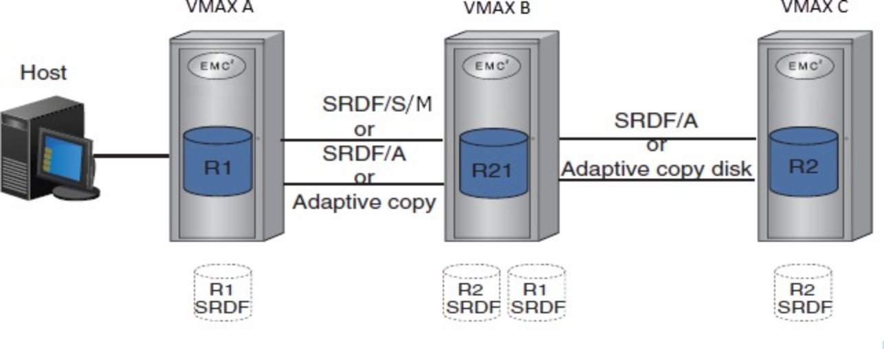
Cascaded SRDF uses dual-role SRDF devices (R21 devices) on the secondary site which acts as both an R2 to the primary site and an R1 to the tertiary site. The R2 SRDF mirror of the R21 device in array B receives data from the R1 SRDF mirror of the R1 device in array A. The R2 SRDF mirror of the R2 device in array C receives data from the R1 SRDF mirror of the R21 device in array B. When data from array A reaches array B, both SRDF mirrors of the R21 device receive updates, but their behavior differs:
- After the R2 SRDF mirror of the R21 device receives updates, data is written to drives in array B. If SRDF operates in synchronous mode, the SRDF emulation sends the acknowledgment to array A.
- After the R1 SRDF mirror of the R21 device receives updates, the SRDF emulation sends data across the SRDF links to the R2 SRDF mirror of the R2 device in array C as shown in Figure 6. When data is received in array C, the R1, R21 and R2 device are synchronized.
Figure 4 shows an example of a VMAX Cascaded SRDF configuration.
Figure 4. Cascaded SRDF example
The benefits of cascaded SRDF are:
- Faster recovery times at the tertiary site enabled by the continuous mirroring from the secondary site to the tertiary site in the event of the primary site failure.
- Tight-integration with TimeFinder product family.
- Management capability by using the current storage management portfolio of software products.
- Geographically dispersed secondary and tertiary sites.
Note: In a Cascaded configuration such as in Figure 4, the SRDF SRA requires that array A recognizes array C as a remote array, even though this is not normally a requirement of a Cascaded configuration. This issue may be addressed in a future version of the SRDF SRA.
Note: The SRDF SRA does not support Cascaded configurations with SRDF/Metro because of the inability to guarantee that a Cascaded configuration will not be converted to a Concurrent configuration when using a witness.
[3] See section EmcSrdfSraGlobalOptions.xml contents.
[4] When the protocol is supported by the VMAX/PowerMax platform.