
Recovery after failure of compute environment
Recovery after failure of compute environment
-
Recovery after failure of compute environment
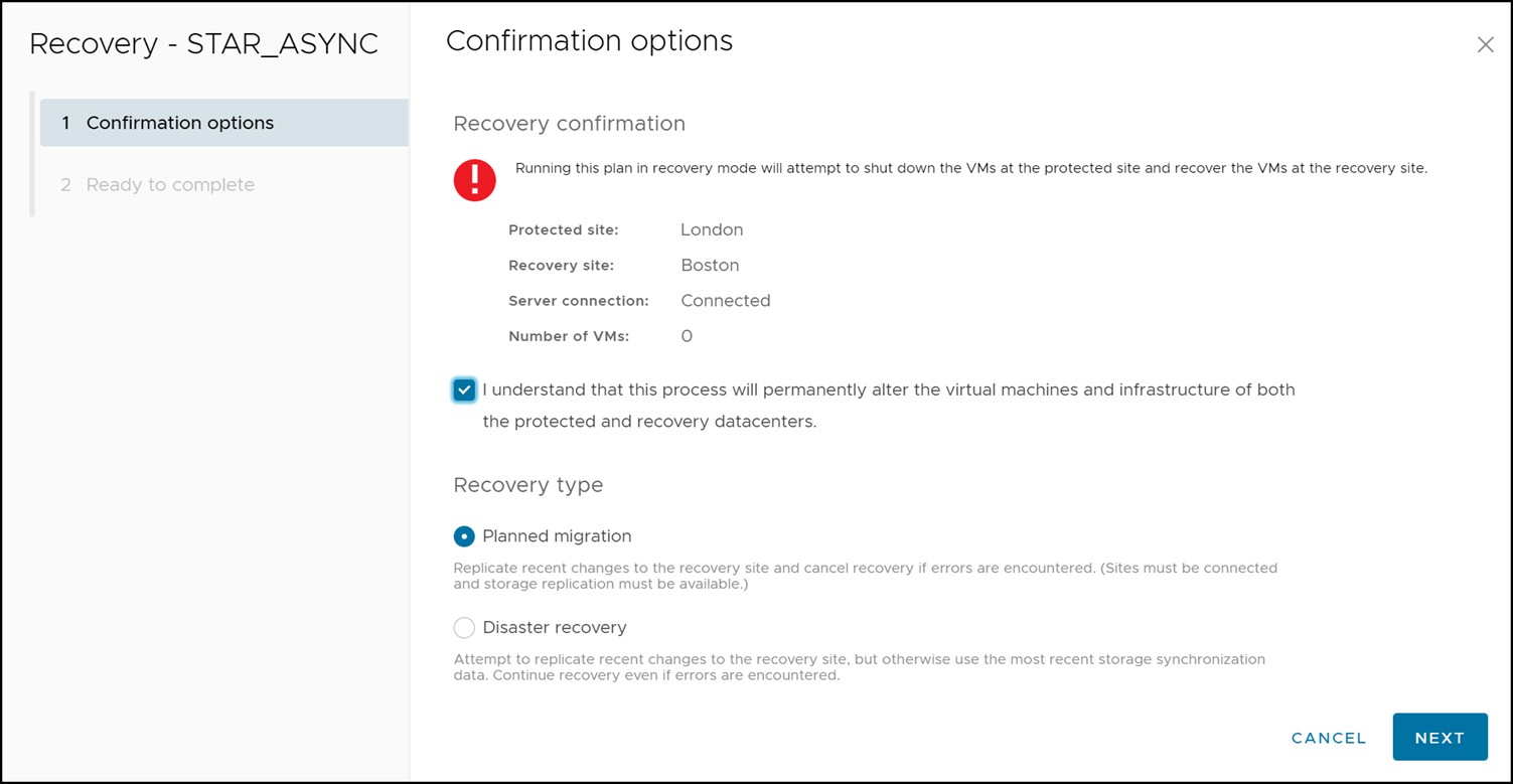
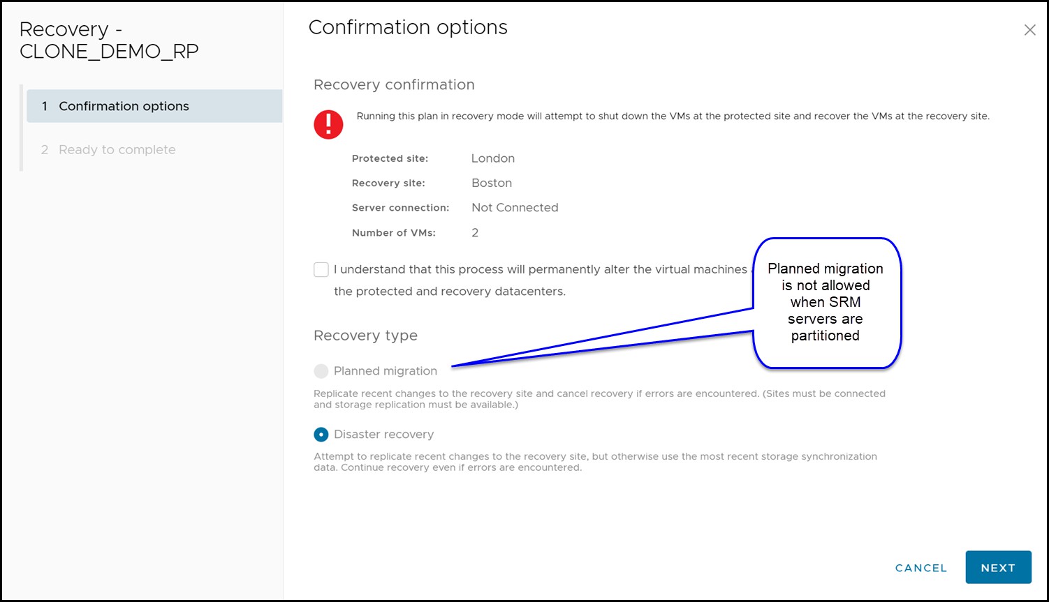
Situations can arise where there is a failure that is limited to the compute environment while storage and replication remains online. This section assumes that the VMware environment on the protected site is down and cannot be contacted over the network by the recovery site. This leads to a disconnected state for the SRM server pairing and planned migrations will not be allowed. In this situation only “Disaster Recovery” is offered as a valid option for failover recovery modes as seen in Figure 161.
Figure 161 Recovery options during a compute environment failure

In this scenario, the storage environment remains online and replication has not been halted. Therefore, the SRDF site state is expected to be “Consistent” or “Synchronized”[1].
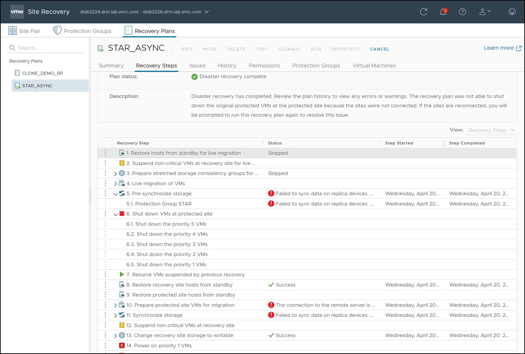
An example recovery plan executed during a compute environment failure of the protected site is shown in Figure 162.
Figure 162 Completed disaster recovery after failed compute environment

There are a few important things to note in Figure 162:
- The steps, “Pre-synchronize Storage” and “Synchronize Storage” fail. This is NOT due to a storage failure. For the SRDF SRA, these steps are non-operations as SRDF ensures synchronized data itself and has no need for this outside additional operation. These steps fail due to the fact that the protected site compute environment is down and attempts to contact the remote SRM server fail.
- “Shutdown VMs at Protected Site” and “Prepare Protected Site VMs for Migration” fail. These are the steps where SRM attempts to gracefully power-down and clean up the protected vCenter before failover. Since the site is down and this is not possible, the operation fails.
- “Change Recovery Site Storage to Writable” succeeds.
With the exception of these failures, the result of the recovery process when the protected site compute environment is down is no different than a normal planned migration. When “Change Recovery Site Storage to Writable” executes, the SRDF SRA follows the same workflow as shown in Table 27 and that is described in the paragraphs following that table.
Recovery after failure of storage and compute environment
In a true disaster scenario, both the compute and storage might become unavailable. This could be due to situations such as:
- Actual physical destruction of the infrastructure
- Loss of power
- WAN failure between the two datacenters, partitioning both network and data replication traffic
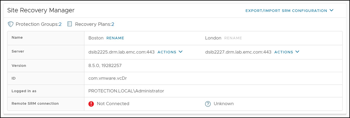
In any of those cases, the recovery SRM server will not be able to contact the protected site. This can be seen in Figure 163 which shows the recovery site SRM server reporting that the protection site is down.
Figure 163 Disconnected protected site SRM server
When the link between the local and remote VMAX array goes down, both links will enter a state of “Partitioned”.
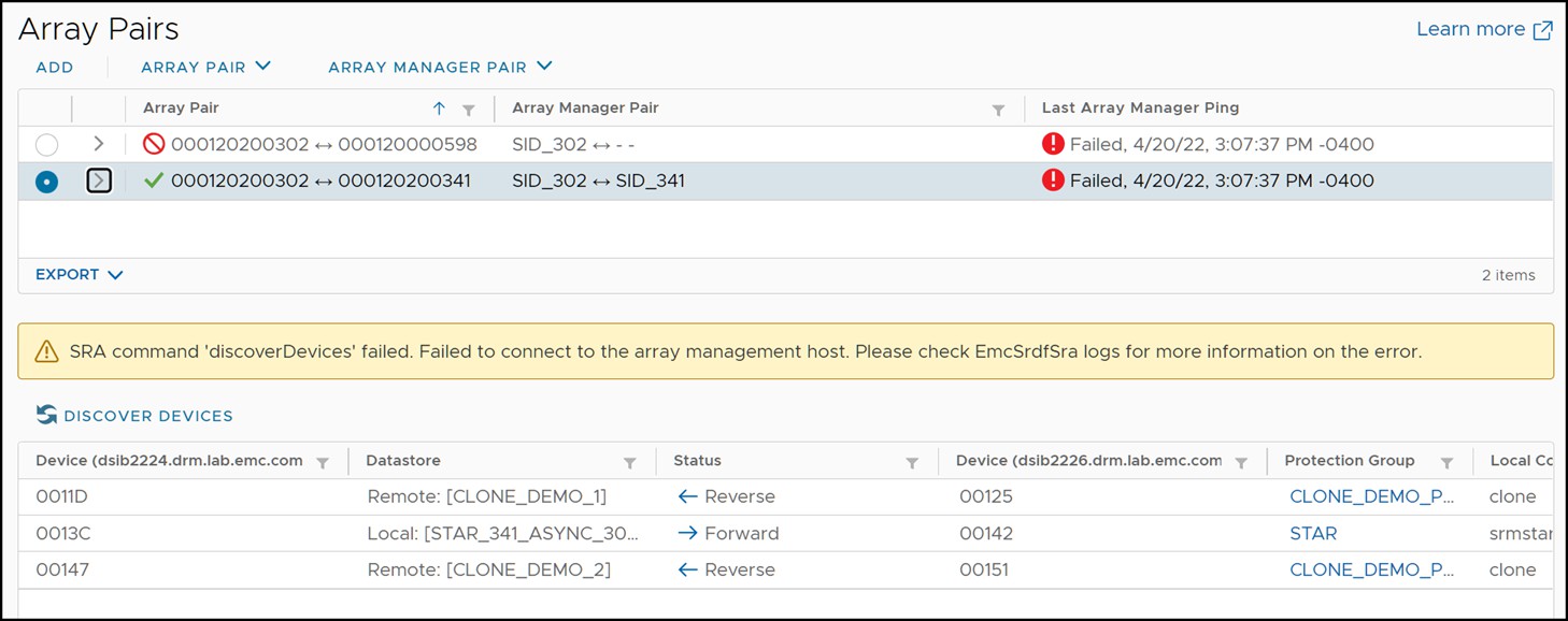
Since the entire workload site failed in this scenario, the array manager will not be able to update its information and the “Devices” screen will not show correct information for all device pairs. This is due to the fact that the protected side Solutions Enabler server is down and the protected side array information cannot be retrieved. An example of this can be seen in Figure 164.
Figure 164 Failed device discovery due to down protected site Solutions Enabler server

To recover the virtual machines on the surviving site, the “Recovery” link should be selected. Since the protected site is completely down the “Disaster Recovery” mode is the only available option. The SRA does not, in principle, act any differently if the “Disaster Recovery” mode is chosen as compared to “Planned Migration”. The SRA will still attempt all operations as it would during a migration and return success or failure. The difference is that SRM will not fail the recovery plan on reception of a failed operation by the SRA. In the case of a protected site complete failure all steps involving the protected site will accordingly fail. Figure 165 shows a recovery plan that has been executed when the protected site has experienced a complete failure and the steps that will fail because of it.
Figure 165 Recovery plan execution during a complete protected site failure
These failed steps can be skipped by selecting the Forced Failover option for disaster recovery.
The following list shows the workflow of the SRDF SRA when recovering Concurrent SRDF when the R1 site has experienced a complete failure:
- R1 site storage and compute fails and RDF links to both sites become partitioned.
- SRDF SRA checks for MSC Cleanup flag on the consistency group on the recovery Solutions Enabler server (for Asynchronous site recovery). If this flag is set the SRDF SRA performs a MSC Cleanup on the group.
- If configured, the SRDF SRA creates and activates the recovery site gold copies.
- The SRDF SRA performs an RDF Failover on the target devices, setting those devices to be read/write enabled and able to be mounted at the recovery site. Since the R1 site is still down the RDF Pair state remains as Partitioned and not Failed Over.
Planned Migration: Cascaded SRDF/Non-Star
The recovery option “Planned Migration” assures a graceful migration of virtual machines from a local vCenter to a remote vCenter. Any errors that the recovery plan encounters will immediately fail the operation and require the user to remediate these errors and restart the migration process. Therefore, a Planned Migration assumes the following things:
- The protected and recovery site VMware environment is up and running (including ESXi hosts, vCenter, virtual machines, SRM server etc.) without issues.
- The storage environment is stable and configured properly. This includes the array(s), the fabric (SAN) and the Solutions Enabler servers configured in the array managers.
- No network connectivity issues.
Before executing a recovery plan failover, it is highly recommended to test the recovery plan first using the “Test” feature offered by SRM. Information on configuring and running a recovery test is discussed in detail in Chapter 4.
The first step is to ensure that RDF Pair is in a proper state. In order to run a successful recovery the RDF Pair state must be either, “Synchronized”, “SyncInProg”, “Consistent”, or “Suspended”. If the RDF pair is in an alternative state, it must either be changed to a proper state using VMAX/PowerMax management applications or a Disaster Recovery operation may need to be run to allow the SRA to ignore invalid RDF pair states.
Generally, a good indicator of valid SRDF status is shown in the “Devices” tab in a given array manager by selecting the array manager and view the “Devices” tab. If the “Direction” column shows a blue directional arrow, it might be a valid candidate for Planned Migration. If the “Direction” column shows a broken gray bar either manual intervention is needed or the Disaster Recovery option might be required. Planned migration will never be allowed in this state.
While the “Direction” column is, in general, a good indicator of RDF pair states it is inadequate to cover the many diverse possibilities of RDF pair states. Therefore, it is advisable to use Unisphere for VMAX/PowerMax[2] or Solutions Enabler to determine the exact status.
A planned migration can be initiated by selecting the appropriate recovery plan and the selecting the “Recovery” link as can be seen in Figure 166.
Figure 166 Initiating a planned migration with SRM

Once the Recovery link has been selected, a short confirmation wizard appears asking to confirm the initiation of the recovery operation and in which mode the recovery plan should be run. This screen is shown in Figure 167.
Figure 167 Recovery operation confirmation wizard
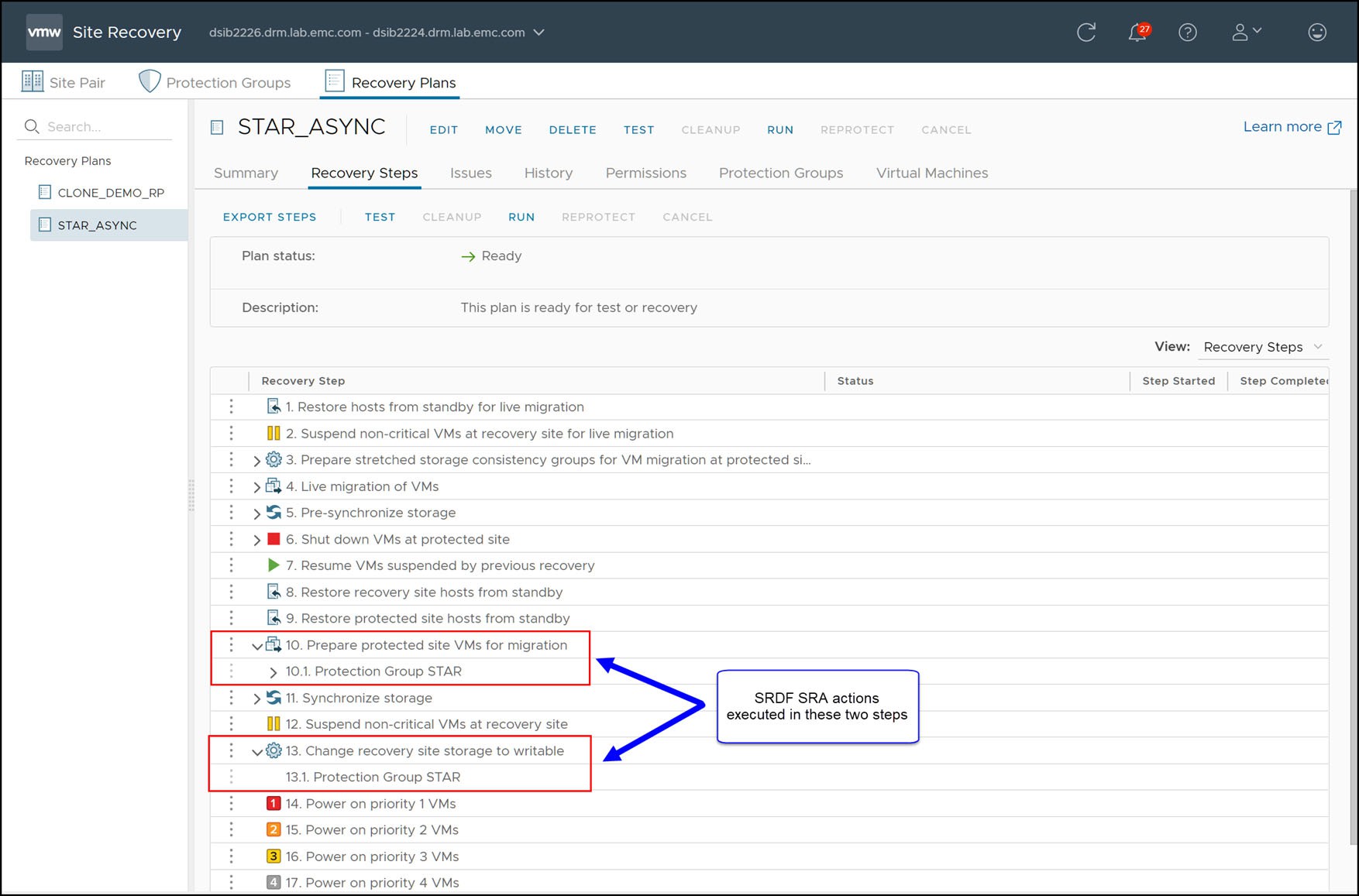
As soon as the wizard completes the recovery operation will commence. During the steps “Prepare Protected Site VMs for Migration” and “Change Recovery Site Storage To Writable”, as shown in Figure 168, the SRDF SRA performs the necessary RDF operations on the devices in the protection group to failover.
Figure 168 Steps of a recovery plan in SRM
The SRDF SRA supports a variety of Cascaded SRDF configurations as well as recovery to either site provided the replication mode on any hop between the workload and the intended target site is not Adaptive Copy. The SRDF SRA supports the following configurations:
- First hop Synchronous, second hop Asynchronous
- First hop Synchronous, second hop Adaptive Copy Disk
- First hop Asynchronous, second hop Adaptive Copy Disk[3]
- First hop Active, second hop Asynchronous
The following table describe the steps for recovery to the secondary site (first hop) with Cascaded SRDF. This site can be replicated to via synchronous or asynchronous replication. The table has six columns:
- SRDF SRA Step #: The chronological order of the operations initiated by the SRDF SRA during recovery.
- Issuing SRDF SRA and Solutions Enabler: During a planned migration, both the protected and recovery site SRAs perform operations to execute the recovery process. The process is split into two separate SRM/SRA interactions: Prepare Failover and Failover. The first few operations are issued by the protected site SRDF SRA during Prepare Failover while the operations executed during the Failover step is owned by the recovery site SRDF SRA. If an error occurs during a given operation refer to the logs of the specified SRDF SRA and/or respective Solutions Enabler server for more information.
- Step Detail: The description of the SRDF SRA operation.
- Protected site after step: The state of the original workload site after the operation.
- Recovery site after step: The state of the recovery site after the operation, this is the secondary site in the Cascaded configuration.
- Bunker site after step: The state of the bunker site after the operation, this is the tertiary site in the Cascaded configuration.
For Cascaded SRDF recovery to the secondary/first hop site, the SRA performs the steps listed in Table 28.
Table 28. Cascaded SRDF failover steps for first hop recovery
SRDF SRA
step #
Issuing SRDF SRA and Solutions Enabler
Step detail
Protected site after step
Recovery site after step
Bunker site after step
1
Protected site
[OPTIONAL] Create protected site gold copies
Workload and read/write enabled
Synchronized (Synchronous replication only) or Consistent and write disabled
Synchronized (ACP_Disk replication only) or Consistent and write disabled
2
Protected site
Suspend replication on hop one
Workload and read/write enabled
Suspended and write disabled
Synchronized (ACP_Disk only) or Consistent and write disabled
3
Protected site
Suspend replication on hop two
Workload and read/write enabled
Suspended and write disabled
Suspended and write disabled
4
Protected site
Write disable R1 devices
Workload and write disabled
Suspended and write disabled
Suspended and write disabled
5
Protected site
[OPTIONAL] Remove R1 devices from storage group
Workload and write disabled
Suspended and write disabled
Suspended and write disabled
6
Recovery site
[OPTIONAL] Create recovery site gold copies
Workload and write disabled
Suspended and write disabled
Suspended and write disabled
7
Recovery site
Perform RDF Failover to recovery site
Write disabled
Workload, Failed Over and read/write enabled
Suspended and write disabled
8
Recovery site
[OPTIONAL] Add R21 devices to storage group
Write disabled
Workload, Failed Over and read/write enabled
Suspended and write disabled
The following table describe the steps for recovery to the tertiary site (second hop) with Cascaded SRDF. This site will always be the asynchronous site. The table has six columns:
- SRDF SRA Step #: The chronological order of the operations initiated by the SRDF SRA during recovery.
- Issuing SRDF SRA and Solutions Enabler: During a planned migration, both the protected and recovery site SRAs perform operations to execute the recovery process. The process is split into two separate SRM/SRA interactions: Prepare Failover and Failover. The first few operations are issued by the protected site SRDF SRA during Prepare Failover while the operations executed during the Failover step is owned by the recovery site SRDF SRA. If an error occurs during a given operation refer to the logs of the specified SRDF SRA and/or respective Solutions Enabler server for more information.
- Step Detail: The description of the SRDF SRA operation.
- Protected site after step: The state of the original workload site after the operation.
- Bunker site after step: The state of the bunker site after the operation, this is the secondary (first hop) site in the Cascaded configuration.
- Recovery site after step: The state of the recovery site after the operation, this is the tertiary (second hop) site in the Cascaded configuration.
For Cascaded SRDF recovery to the tertiary/second hop site, the SRA performs the steps listed in Table 29.
- Cascaded SRDF failover steps for first hop recovery
SRDF SRA
step #
Issuing SRDF SRA and Solutions Enabler
Step detail
Protected site after step
Bunker site after step
Recovery site after step
1
Protected site
[OPTIONAL] Create protected site gold copies
Workload and read/write enabled
Synchronized (Synchronous replication only) and write disabled
Consistent (Asynchronous replication only) and write disabled
2
Protected site
Suspend replication on hop one
Workload and read/write enabled
Suspended and write disabled
Synchronized (ACP_Disk only) or Consistent and write disabled
3
Protected site
Suspend replication on hop two
Workload and read/write enabled
Suspended and write disabled
Suspended and write disabled
4
Protected site
Write disable R1 devices
Workload and write disabled
Suspended and write disabled
Suspended and write disabled
5
Protected site
[OPTIONAL] Remove R1 devices from storage group
Workload and write disabled
Suspended and write disabled
Suspended and write disabled
6
Recovery site
[OPTIONAL] Create recovery site gold copies
Workload and write disabled
Suspended and write disabled
Suspended and write disabled
7
Recovery site
Perform RDF Failover to recovery site
Write disabled
Suspended and write disabled
Workload, Failed Over and read/write enabled
8
Recovery site
[OPTIONAL] Add R2 devices to storage group
Write disabled
Suspended and write disabled
Workload, Failed Over and read/write enabled
Once the R2/21 devices are write-enabled, the devices can be mounted and the virtual machines can be registered and powered-on. In addition to the R2/21 devices being mounted on the recovery-side ESXi hosts, the R1 volumes will be unmounted and detached from the protection-side ESXi hosts.
When the VMFS volumes on the (now) R1 devices are mounted the ESXi kernel must resignature the VMFS first because it is seen as a copy due to its invalid signature. The reason for the invalid signature, and therefore the subsequent resignaturing, is due to the fact that the R1 and R2 devices have different world-wide names (WWNs) but an identical VMFS volume. The VMFS volume was (most likely) originally created on the R1 device and the signature of the VMFS is based, in part, on the WWN of the underlying device. Since the WWN changes between the R1 and the R2 and the signature is copied over, the ESXi kernel will identify a WWN/VMFS signature mismatch and resignature.
The VMware kernel automatically renames VMFS volumes that have been resignatured by adding a “SNAP-XXXXXX” prefix to the original name to denote that it is a copied and resignatured file system. VMware vCenter Site Recovery Manager provides an advanced setting, that is disabled by default, storageProvider.fixRecoveredDatastoreNames. Enabling this setting will cause this suffix to be automatically removed during the recovery plan. Check this option on the recovery site SRM server to enable this automatic prefix removal behavior.
Disaster Recovery·Cascaded SRDF/Non-Star
The recovery option “Disaster Recovery” should be selected for recovery when there are issues with the infrastructure that will prevent a graceful recovery of virtual machines from a local vCenter to a remote vCenter. Unlike the “Planned Migration” option, most errors that the recovery plan encounters will be ignored by SRM. The only errors that will prevent a recovery in disaster recovery mode are failures in the recovery site infrastructure. Anything between minor errors to a complete failure of the protected site infrastructure will not prevent recovery.
If possible, the “Planned Migration” is preferable as it will more likely allow for a clean subsequent reprotection and/or failback. Therefore, if errors are encountered an earnest attempt to remediate them should be made. If these errors cannot be fixed (due to equipment failure or if time is of the essence and the virtual environment must be recovered as quickly as possible) the “Disaster Recovery” option should be selected.
This section will discuss disaster recovery failover in two parts:
- Recovery after failure of compute environment
- Recovery after failure of storage and compute environment
Recovery after failure of compute environment
Situations can arise where there is a failure that is limited to the compute environment while storage and replication remains online. This section assumes that the VMware environment on the protected site is down and cannot be contacted over the network by the recovery site. This leads to a disconnected state for the SRM server pairing and planned migrations will not be allowed. In this situation only “Disaster Recovery” is offered as a valid option for failover recovery modes as seen in Figure 169.
Figure 169 Recovery options during a compute environment failure
In this scenario, the storage environment remains online and replication has not been halted. Therefore, the SRDF site state is expected to be “Consistent”[4].
An example recovery plan executed during a compute environment failure of the protected site is shown in Figure 170.
Figure 170 Completed disaster recovery after failed compute environment

There are a few important things to note in Figure 170:
- The steps, “Pre-synchronize Storage” and “Synchronize Storage” fail. This is NOT due to a storage failure. For the SRDF SRA, these steps are non-operations as SRDF ensures synchronized data itself and has no need for this outside additional operation. These steps fail simply due to the fact that the protected site compute environment is down and attempts to contact the remote SRM server fail.
- “Shutdown VMs at Protected Site” and “Prepare Protected Site VMs for Migration” fail. These are the steps where SRM attempts to gracefully power-down and clean up the protected vCenter before failover. Since the site is down and this is not possible, the operation fails.
- “Change Recovery Site Storage to Writable” succeeds.
With the exception of these failures, the result of the recovery process when the protected site compute environment is down is no different to a normal planned migration. When “Change Recovery Site Storage to Writable” executes, the SRDF SRA follows the same workflow as shown in Table 28 and that is described in the paragraphs following that table.
Recovery after failure of storage and compute environment
In a true disaster scenario, both the compute and storage might become unavailable. This could be due to situations such as:
- Actual physical destruction of the infrastructure
- Loss of power
- WAN failure between the two datacenters, partitioning both network and data replication traffic
In any of those cases, the recovery SRM server will not be able to contact the protected site. This can be seen in Figure 171 which shows the recovery site SRM server reporting that the protection site is down.
Figure 171 Disconnected protected site SRM server

When the link between the local and remote VMAX array goes down, both links will enter a state of “Partitioned”.
Since the entire workload site failed in this scenario, the array manager will not be able to update its information and the “Devices” screen will not show correct information for all device pairs. This is due to the fact that the protected side Solutions Enabler server is down and the protected side array information cannot be retrieved. An example of this can be seen in Figure 172.
Figure 172 Failed device discovery due to down protected site Solutions Enabler server
To recover the virtual machines on the surviving site, the “Recovery” link should be selected. Since the protected site is completely down the “Disaster Recovery” mode is the only available option. The SRA does not, in principle, act any differently if the “Disaster Recovery” mode is chosen as compared to “Planned Migration”. The SRA will still attempt all operations as it would during a migration and return success or failure. The difference is that SRM will not fail the recovery plan on reception of a failed operation by the SRA. In the case of a protected site complete failure all steps involving the protected site will accordingly fail. Figure 173 shows a recovery plan that has been executed when the protected site has experienced a complete failure and the steps that will fail because of it.
Figure 173 Recovery plan execution during a complete protected site failure

These failed steps can be skipped by selecting the Forced Failover option for disaster recovery.
The following list shows the workflow of the SRDF SRA when recovering Cascaded SRDF when the R1 site has experienced a complete failure:
- R1 site storage and compute fails and RDF links from the R1 become partitioned and the RDF link between the secondary and the tertiary sites remains consistent.
- SRDF SRA checks for MSC Cleanup flag on the consistency group on the recovery Solutions Enabler server. If this flag is set the SRDF SRA performs a MSC Cleanup on the group.
- If configured, the SRDF SRA creates and activates the recovery site gold copies.
- The SRDF SRA performs an RDF Failover on the target devices, setting those devices to be read/write enabled so that they can be mounted at the recovery site.
[1] Disaster recovery mode also tolerates other SRDF states, but these states are discussed in the ensuing section.
[2] If the group is a composite group, Solutions Enabler must be used to query RDF status as this group type is not yet supported for use with Unisphere for VMAX/PowerMax.
[3] Adaptive Copy Write Pending mode is not supported on any hop in Cascaded SRDF configurations. Recovery operations with Write Pending mode enabled on any hop in the Cascaded configuration will fail.
[4] Disaster recovery mode also tolerates other SRDF states, but these states are discussed in the ensuing section.