
Recovery after failure of compute environment
Recovery after failure of compute environment
-
Recovery after failure of compute environment
Situations can arise where there is a failure that is limited to the compute environment while storage and replication remains online. This section assumes that the VMware environment on the protected site is down and cannot be contacted over the network by the recovery site. This leads to a disconnected state for the SRM server pairing and planned migrations will not be allowed. In this situation only “Disaster recovery” is a valid option for failover recovery modes, even if Planned migration is presented.
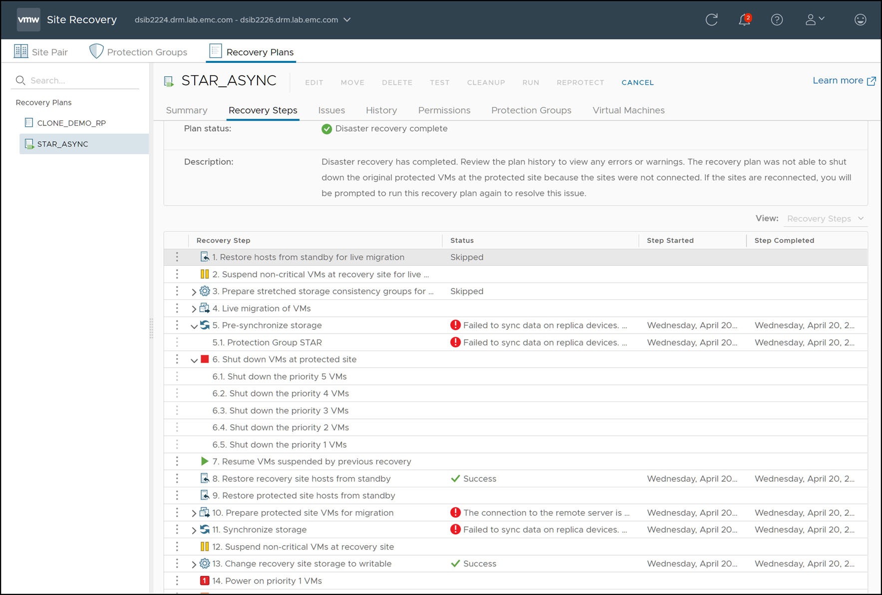
In this scenario, the storage environment remains online and replication has not been halted. Therefore, the SRDF/Star state is expected to be “Protected”[1]. An example recovery plan executed during a compute environment failure of the protected site is shown in Figure 137.
Figure 137. Completed disaster recovery after failed compute environment

There are a few important things to note in Figure 137:
- The steps, “Pre-synchronize storage” and “Synchronize storage” fail. This is NOT due to a storage failure. For the SRDF SRA, these steps are non-operations as SRDF ensures synchronized data itself and has no need for this outside additional operation. These steps fail simply due to the fact that the protected site compute environment is down and attempts to contact the remote SRM server fail.
- “Prepare protected site VMs for migration” fail. These are the steps where SRM attempts to gracefully power-down and clean up the protected vCenter before failover. Since the site is down and this is not possible, the operation fails.
- “Change recovery site storage to writable” succeeds.
With the exception of these failures, the result of the recovery process when the protected site compute environment is down is no different to a normal planned migration. When “Change recovery site storage to writable” executes, the SRDF SRA follows the same workflow as shown in Table 20 or Table 21 (depending on whether recovery is to the synchronous site or asynchronous site respectively).
Recovery after failure of storage and compute environment
In a true disaster scenario, both the protected site compute and storage might become unavailable. This could be due to situations such as:
- Actual physical destruction of the infrastructure
- Loss of power
- WAN failure between the two datacenters, partitioning both network and data replication traffic
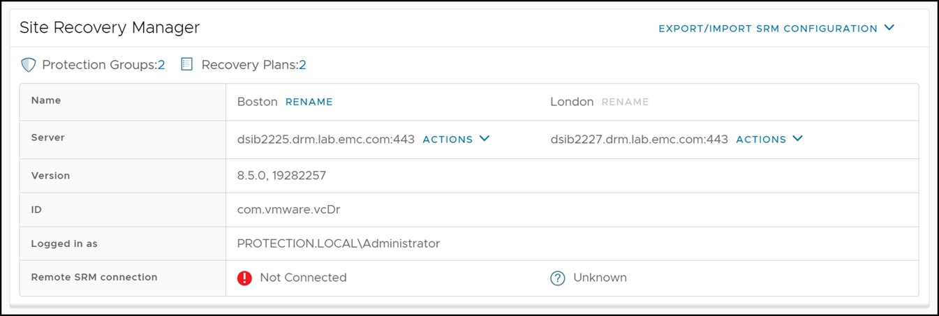
In any of those cases, the recovery SRM server will not be able to contact the protected site. This can be seen in Figure 138 which shows the recovery site SRM server reporting that the protection site is down.
Figure 131. Disconnected protected site SRM server

When the link between the local and remote PowerMax array becomes “Partitioned” (referred to as “PathFail” by SRDF/Star), SRDF/Star enters a “Tripped” state. For example, in a Concurrent SRDF/Star environment that has been tripped because the protected site has experienced a total failure, the STAR state will show as “Tripped” and the 1st and 2nd Target Sites as “PathFail”.
While a variety of states are allowed for discovery of SRDF/Star devices, only two SRDF/Star states are allowed for failover, be it Disaster Recovery mode or Planned Migration mode. The SRDF/Star state must be either “Protected” (the only state supported by Planned Migration) or “Tripped”. Disaster Recovery supports both states. Any other state requires user intervention to configure it to a valid state before recovery.
Since the entire workload site failed in this scenario, the array manager will not be able to update its information and the pairs screen may not show the correct information for all device pairs as it will show the last known state. This is due to the fact that the protected side Solutions Enabler server is down and the protected side array information cannot be retrieved. Notice that the arrays cannot be pinged, and the SRA warns it cannot discover devices. An example of this can be seen in Figure 139.
Figure 139. Failed device discovery due to an off-line protected site Solutions Enabler server

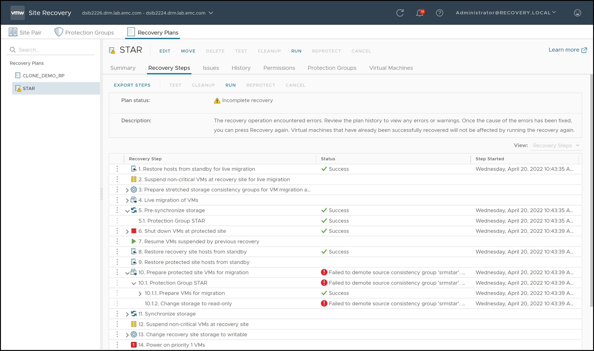
To recover the virtual machines on the surviving site, the “Recovery” link should be selected. Since the protected site is completely down the “Disaster Recovery” mode is the only available option. The SRA does not, in principle, act any differently if the “Disaster Recovery” mode is chosen as compared to “Planned Migration”. The SRA will still attempt all operations as it would during a migration and return success or failure. The difference is that SRM will not fail the recovery plan on reception of a failed operation by the SRA. In the case of a complete failure of the protected site all steps involving the protected site will accordingly fail. Figure 140 shows a recovery plan that has been executed when the protected site has experienced a complete failure and the steps that will fail because of it.
Figure 140. Recovery plan execution during a complete protected site failure
These failed steps can be skipped by selecting the Forced Failover option for disaster recovery.
In a complete failure of the protected site, both the Asynchronous site and the Synchronous site enter the “PathFail” state. Figure 141 schematically depicts a Concurrent SRDF/Star environment when it has experienced a complete protected site failure.
Figure141. Concurrent SRDF/Star with workload site failure
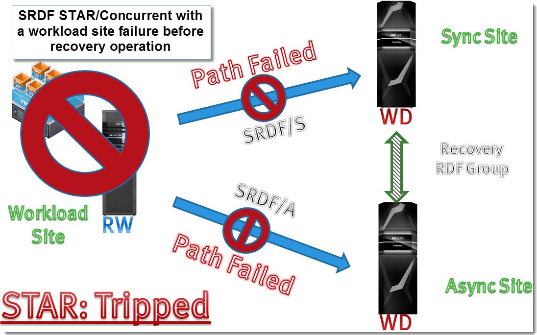
Table 22 shows the process steps taken by the SRDF SRA when recovering a Concurrent SRDF/Star setup to the Synchronous site with the Workload site down while Table 23 includes the process steps for the Asynchronous site.
Table 22. Concurrent SRDF/Star recovery to Sync site workflow
SRDF SRA step #
Step detail
Resulting SRDF/Star state
Site A after step
Site B after step
Site C after step
1
State before failover
Tripped
Workload
PathFail
PathFail CleanReq[2]
2
Check if MSC cleanup is needed and perform a symstar cleanup on affected site. Required cleanup is denoted by the path being in the “Pathfail CleanReq” state
Tripped
Workload
PathFail
PathFail
3
[OPTIONAL] Create recovery site gold copy
Tripped
Workload
PathFail
PathFail
4
Switch Workload site (site A) to site B with “keep data” set to site B
Unprotected
Disconnected
Workload
Disconnected
5
Attempt to connect site A (will fail)
Unprotected
Disconnected
Workload
Disconnected
6
Connect site C
Unprotected
Disconnected
Workload
Connected
7
Attempt to protect site A (will fail)
Unprotected
Disconnected
Workload
Connected
8
Protect site C
Unprotected
Disconnected
Workload
Protected
9
[OPTIONAL] Add R2 devices to storage group
Unprotected
Disconnected
Workload
Protected
Table 23. Concurrent SRDF/Star recovery to Async site workflow
SRDF SRA step #
Step detail
Resulting SRDF/Star state
Site A after step
Site B after step
Site C after step
1
Protected site (storage and compute) goes down
Tripped
Workload
PathFail
PathFail CleanReq[3]
2
Check if MSC cleanup is needed and perform a symstar cleanup on affected site. Required cleanup is denoted by the path being in the “Pathfail CleanReq” state
Tripped
Workload
PathFail
PathFail
3
[OPTIONAL] Create recovery site gold copy
Tripped
Workload
PathFail
PathFail
4
Switch Workload site to site C from site A with “keep data” set to site C
Unprotected
Disconnected
Disconnected
Workload
5
Attempt to connect original workload target site (site A) which will fail
Unprotected
Disconnected
Disconnected
Workload
6
Connect site B (adaptive copy)
Unprotected
Disconnected
Connected
Workload
7
Attempt to protect site A (will fail)
Unprotected
Disconnected
Connected
Workload
8
Protect site B (set RDF mode to Asynchronous)
Unprotected
Disconnected
Protected
Workload
9
[OPTIONAL] Add R2 devices to storage group
Unprotected
Disconnected
Protected
Workload
All of these steps occur during the step entitled “Change Recovery Site Storage to Writable”. The remainder of the recovery process is no different in result than the recovery processes discussed earlier in this chapter.
Configuration: Cascaded SRDF/Star
Detailed step-by-step configuration of SRDF/Star is beyond the scope of this book but there are some important considerations to note before configuring for SRM.
The SRDF SRA supports failover to the synchronous and asynchronous site (also sometimes referred to as the tertiary site).
The protected SRM server and vCenter server must be located at the appropriate SRDF/Star sites to support failover to the desired site. In other words, the protected VMware compute environment must always be at the workload site and the recovery VMware compute environment must be at the SRDF/Star synchronous site in order to failover to the synchronous site or at the asynchronous site in order to support failover to the asynchronous site. The location of the compute environment in accordance with the SRDF/Star environment dictates where the SRDF SRA permits failover to for that given configuration. Once a topology has been configured, failover may only occur between the original workload site and the configured target site, be it the synchronous site or the asynchronous site. Whichever site does not host one of the two SRM-protected compute environments is deemed a bunker site by the SRDF SRA and therefore will not be managed by the SRDF SRA.
Note: The SRDF SRA advanced option FailoverToAsyncSite must be set to NO to allow recovery to the Synchronous site or YES to allow recovery to the Asynchronous site. This option must be set identically on both the recovery and protected SRM servers.
Planned Migration: Cascaded SRDF/Star
The recovery option “Planned Migration” assures a graceful migration of virtual machines from a local vCenter to a remote vCenter. Any errors that the recovery plan encounters will immediately fail the operation and require the user to remediate these errors and restart the migration process. Therefore, a Planned Migration assumes the following things (among other details):
- The protected and recovery site VMware environment is up and running (including ESXi hosts, vCenter, virtual machines, SRM server etc.) without issues.
- The storage environment is stable and configured properly. This includes the array(s), the fabric (SAN) and the Solutions Enabler servers configured in the array managers.
- No network connectivity issues.
Before executing a recovery plan failover, it is highly recommended to test the recovery plan first (preferably multiple times) using the “Test” feature offered by SRM. Information on configuring and running a recovery test is discussed in detail in Chapter 4.
The first step is to ensure that SRDF/Star is in a proper state. In order to run a successful recovery the SRDF/Star state must be “Protected”. If SRDF/Star is in an alternative state, it must either be changed to a proper state using VMAX/PowerMax management applications or a Disaster Recovery operation may need to be run to ignore an invalid SRDF/Star state.
Generally, a good indicator of valid SRDF/Star status is shown in the “Devices” tab in a given array manager by selecting the array manager and view the “Devices” tab. If the “Direction” column shows a blue directional arrow, it might be a valid candidate for Planned Migration. This is slightly different than with 2-site SRDF however, as 3-site SRDF has additional limitations on what state the devices can be in to allow failover which are not reflected within the “Devices” tab. Not only do the device pairs need to be replicating, but they need to be consistent. In SRDF/Star terminology, this means that both the Asynchronous site and the Synchronous site must be in the “Protected” state and SRDF/Star must be in the overall “Protected” state. The SRA requires that SRDF/Star is “Protected” so if either site is not in the “Protected” state, SRDF/Star cannot be in the proper state and Planned Migration will fail. The SRDF SRA log will report errors, such as the errors below, after a failed recovery plan due to invalid SRDF/Star state:
[01/16 13:18:00 16212 0569
SraStarGroup::IsValidStarState] STAR Group state is Unprotected.
[01/16 13:18:00 16212 0985
SraStarGroup::ValidateInputDevices] [WARNING]: The STAR state is not valid. Exiting
[01/16 13:18:00 16212 3018
PrepareFailoverCommand::RunOnGroup] [ERROR]: Input device validation succeeded but one/many of the adapter's conditions is not met. Exiting with failure
Example errors of a failed recovery plan due to invalid SRDF/Star state can be seen in Figure 142.
Figure 142. Failed planned migration due to invalid SRDF/Star state
If the “Direction” column shows a broken gray bar either manual intervention is required or the Disaster Recovery option must be selected. Planned migration will never be allowed in this state.
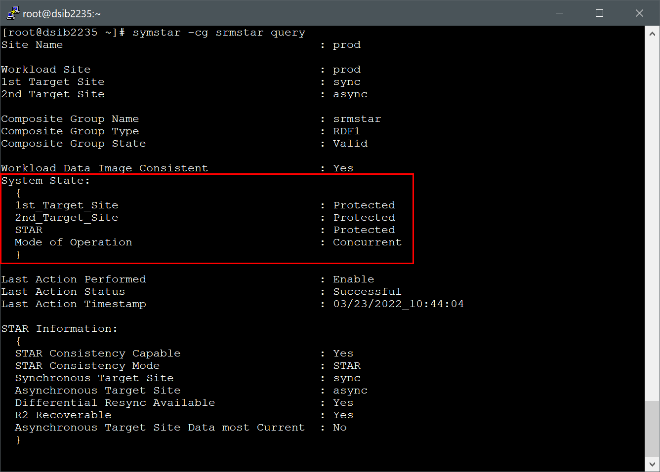
While the “Direction” column is, in general, a good indicator of RDF pair states it is inadequate to cover the many diverse possibilities of SRDF/Star states. Therefore, it is advisable to use Solutions Enabler to determine the exact status. A valid SRDF/Star group for Planned Migration is shown in Figure 143. Note that the 1st Target (synchronous site), the 2nd Target (the asynchronous site) and SRDF/Star state itself all report as “Protected”.
Figure 143. Valid SRDF/Star state for Planned Migration
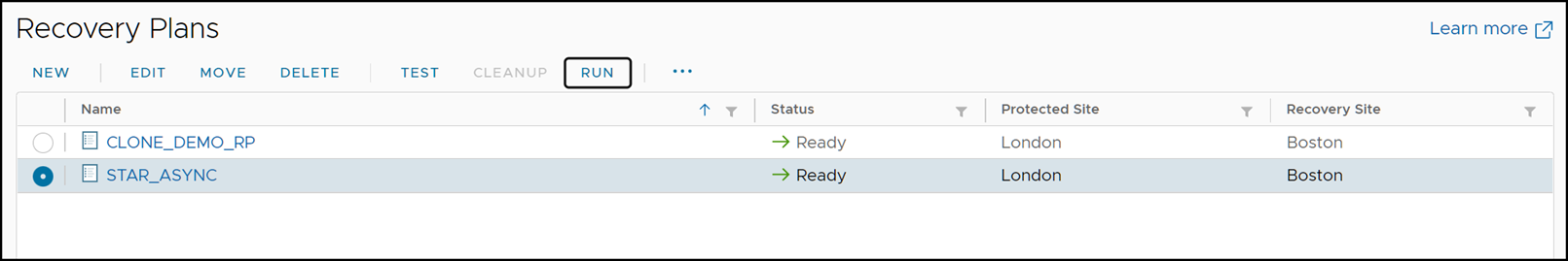
At this point, a planned migration can be initiated by selecting the appropriate recovery plan and the selecting the “Recovery” link as can be seen in Figure 144
Figure 144. Initiating a planned migration with SRM
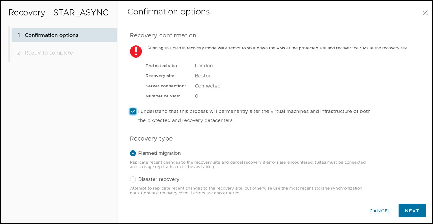
Once the Recovery link has been selected, a short confirmation wizard appears asking to confirm the initiation of the recovery operation and in which mode the recovery plan should be run. This screen is shown in Figure 145.
Figure 145. Recovery operation confirmation wizard
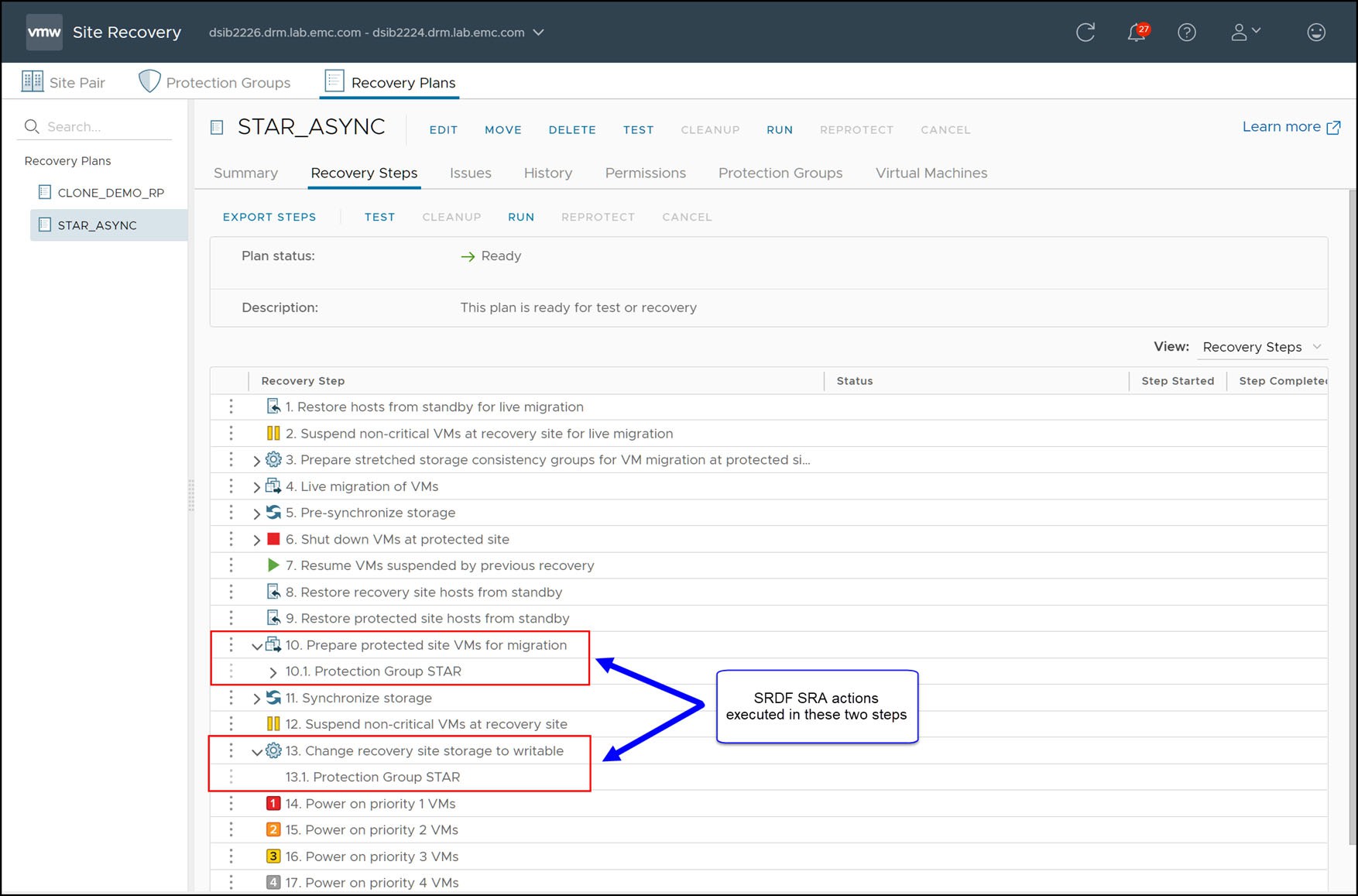
As soon as the wizard completes, the recovery operation will commence. During the steps “Prepare Protected Site VMs for Migration” and “Change Recovery Site Storage To Writable”, as shown in Figure 146, the SRDF SRA performs the necessary Star operations on the devices in the protection group to failover.
Figure 146. Steps of a recovery plan in SRM
The following two tables describe the steps for recovery with Cascaded SRDF/Star. The tables have seven columns:
- SRDF SRA Step #: The chronological order of the operations initiated by the SRDF SRA during recovery.
- Issuing SRDF SRA and Solutions Enabler: Due to certain Star requirements certain operations must be issued from certain Solutions Enabler server (for example symstar halt must be issued by the workload Solutions Enabler server). Therefore the first few operations are issued by the protected site SRDF SRA and consequently the protected site Solutions Enabler server. If an error occurs during a given operation refer to the specified SRDF SRA server or Solutions Enabler server listed for that operation for the correct logs.
- Step Detail: The description of the SRDF SRA operation.
- Site A after step: The state of the original workload site after the operation.
- Site B after step: The state of the original synchronous target site after the operation.
- Site C after step: The state of the original asynchronous target site after the operation.
For Cascaded SRDF/Star recovery to the Synchronous site, the SRA performs the steps listed in Table 24. For Cascaded SRDF/Star recovery to the Asynchronous site, the SRA performs the steps listed in Table 25.
Table 24. Cascaded SRDF/Star steps for Synchronous Recovery
SRDF SRA step #
Issuing SRDF SRA and Solutions Enabler
Step detail
Resulting SRDF/Star state
Site A after step
Site B after step
Site C after step
1
Protected site
[OPTIONAL] Create protected site gold copies
Protected
Workload
Protected
Protected
2
Protected site
[OPTIONAL] Remove R1 devices from storage group
Protected
Workload
Protected
Protected
3
Protected site
Halt Star
Unprotected
Workload
Halted
Halted
4
Recovery site
[OPTIONAL] Create recovery site gold copies
Unprotected
Workload
Halted
Halted
5
Recovery site
Switch Workload site. The original Workload site is now the Sync site and vice versa.
Unprotected
Disconnected
Workload
Disconnected
6
Recovery site
Connect Sync target site
Unprotected
Connected
Workload
Disconnected
7
Recovery site
Connect Async target site
Unprotected
Connected
Workload
Connected
8
Recovery site
Protect Sync target site
Unprotected
Protected
Workload
Connected
9
Recovery site
Protect Async target site
Unprotected
Protected
Workload
Protected
10
Recovery site
Enable Star
Protected
Protected
Workload
Protected
11
Recovery site
[OPTIONAL] Add R2 devices to storage group
Protected
Protected
Workload
Protected
Table 25. Cascaded SRDF/Star steps for Asynchronous Recovery
SRDF SRA
step #
Issuing SRDF SRA and Solutions Enabler
Step detail
Resulting SRDF/Star state
Site A after step
Site B after step
Site C after step
1
Protected site
[OPTIONAL] Create protected site gold copies
Protected
Workload
Protected
Protected
2
Protected site
[OPTIONAL] Remove R1 devices from storage group
Protected
Workload
Protected
Protected
3
Protected site
Halt Star
Unprotected
Workload
Halted
Halted
4
Recovery site
[OPTIONAL] Create recovery site gold copies
Unprotected
Workload
Halted
Halted
5
Recovery site
Switch Workload site. The original Workload site is now the Async site and vice versa.
Unprotected
Disconnected
Disconnected
Workload
6
Recovery site
Connect Async target site
Unprotected
Disconnected
Connected
Workload
7
Recovery site
Connect Sync target site
Unprotected
Connected
Connected
Workload
8
Recovery site
Protect Async target site
Unprotected
Connected
Protected
Workload
9
Recovery site
[OPTIONAL] Add R2 devices to storage group
Unprotected
Connected
Protected
Workload
Readers may note an important difference between the Asynchronous recovery and the Synchronous recovery, that being the end state of Star is not fully protected in an Asynchronous recovery unlike Synchronous recovery. This is due to the fact that it is not permitted to have a Cascaded environment that replicates Asynchronously on the first hop and Synchronously on the second hop. Consequently the SRDF SRA can only Connect the “Synchronous” site (the original workload site) which leaves it in Adaptive Copy Disk mode.
Note: In Cascaded SRDF/Star environments that have been recovered to the Asynchronous target site, test failover back to the original workload site, with or without TimeFinder, (“without” referring to enabling the advanced setting TestFailoverWithoutLocalSnapshots) is not supported. Only full recovery back to the original workload site is supported with the SRDF SRA.
Unlike 2-site SRDF, the SRA will in fact reverse the replication of direction and enable consistency during the failover process. For 2-site SRDF solutions, this replication reversal is reserved for the “Reprotect” operation. Due to the requirements inherent in SRDF/Star these steps are included in the failover process.
Once the SRDF/Star switch workload process has completed, the Synchronous target site devices are now write enabled so the devices will be mounted and the virtual machines will be registered and powered-on. The SRDF/Star switch workload process will swap the RDF personalities of the devices and the change the site definitions within the SRDF/Star configuration. With Cascaded SRDF/Star recovery to the Synchronous site the R21 devices become R1 devices and the R1 devices become R21 devices while the R2 devices are not changed. For Asynchronous recovery, the R21 devices remain static and the R1 and R2 devices personalities are swapped.
In addition to the R2/21 devices being mounted on the recovery-side ESXi hosts, the R1 volumes will be unmounted and detached from the protection-side ESXi hosts.
When the VMFS volumes on the R2 devices are mounted the ESXi kernel must resignature the VMFS first because it is seen as a copy due to its invalid signature. The reason for the invalid signature, and therefore the subsequent resignaturing, is due to the fact that the R1 and R2 devices have different world-wide names (WWNs) but an identical VMFS volume. The VMFS volume was (most likely) originally created on the R1 device and the signature of the VMFS is based, in part, on the WWN of the underlying device. Since the WWN changes between the R1 and the R2 and the signature is copied over, the ESXi kernel will identify a WWN/VMFS signature mismatch and resignature.
The VMware kernel automatically renames VMFS volumes that have been resignatured by adding a “SNAP-XXXXXX” prefix to the original name to denote that it is a copied file system. VMware vCenter Site Recovery Manager provides an advanced setting (disabled by default), storageProvider.fixRecoveredDatastoreNames, that will cause this suffix to be automatically removed during the recovery plan.
Disaster Recovery: Cascaded SRDF/Star
The recovery option “Disaster Recovery” should be selected for recovery when there are issues with the infrastructure that will prevent a graceful recovery of virtual machines from a local vCenter to a remote vCenter. Unlike the “Planned Migration” option, most errors that the recovery plan encounters will be ignored by SRM. The only errors that will prevent a recovery in disaster recovery mode are failures in the recovery site infrastructure. Anything from minor errors to a complete failure of the protected site infrastructure will not prevent recovery.
If possible, the “Planned Migration” is preferable as it will more likely allow for a clean subsequent reprotection and/or failback. Therefore, if errors are encountered an earnest attempt to remediate them should be made. If these errors cannot be fixed (due to equipment failure or if time is of the essence and the virtual environment must be recovered as quickly as possible) the “Disaster Recovery” option should be selected.
This section will discuss disaster recovery failover in two parts:
- Recovery after failure of compute environment
- Recovery after failure of storage and compute environment
Recovery after failure of compute environment
Situations can arise where there is a failure that is limited to the compute environment while storage and replication remains online. This section assumes that the VMware environment on the protected site is down and cannot be contacted over the network by the recovery site. This leads to a disconnected state for the SRM server pairing and planned migrations will not be allowed. In this situation only “Disaster recovery” is offered as a valid option for failover recovery modes as seen in Figure 147.
Figure 147. Recovery options during a compute environment failure
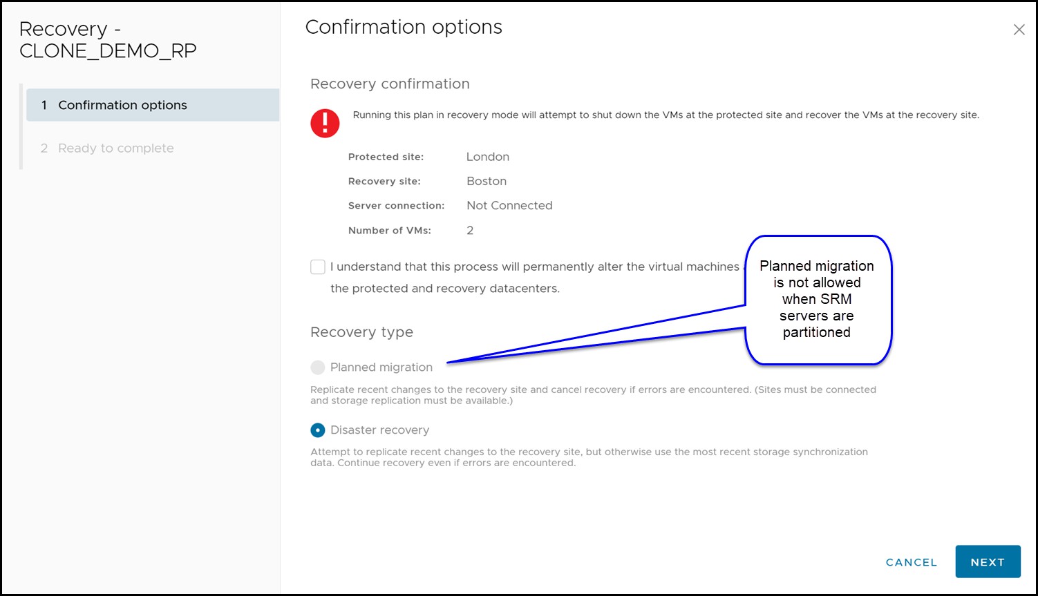
Note: SRM does not always recognize the disconnected state, so it is possible for Planned migration to be available. In such cases it is the user’s responsibility to see the sites are not connected and run a Disaster recovery.
In this scenario, the storage environment remains online and replication has not been halted. Therefore, the SRDF/Star state is expected to be “Protected”[4].
An example recovery plan executed during a compute environment failure of the protected site is shown in Figure 148.
Figure 148. Completed disaster recovery after failed compute environment

There are a few important things to note in Figure 148:
- The steps, “Pre-synchronize Storage” and “Synchronize Storage” fail. This is NOT due to a storage failure. For the SRDF SRA, these steps are non-operations as SRDF ensures synchronized data itself and has no need for this outside additional operation. These steps fail simply due to the fact that the protected site compute environment is down and attempts to contact the remote SRM server fail.
- “Shutdown VMs at Protected Site” and “Prepare Protected Site VMs for Migration” fail. These are the steps where SRM attempts to gracefully power-down and clean up the protected vCenter before failover. Since the site is down and this is not possible, the operation fails.
- “Change Recovery Site Storage to Writable” succeeds.
With the exception of these failures, the result of the recovery process when the protected site compute environment is down is no different to a normal planned migration. When “Change Recovery Site Storage to Writable” executes, the SRDF SRA follows the same workflow as shown in Table 24 or Table 25 (depending on whether recovery is to the synchronous site or asynchronous site respectively).
Recovery after failure of storage and compute environment
In a true disaster scenario, both the compute and storage might become unavailable. This could be due to situations such as:
- Actual physical destruction of the infrastructure
- Loss of power
- WAN failure between the two datacenters, partitioning both network and data replication traffic
In any of those cases, the recovery SRM server will not be able to contact the protected site. This can be seen in Figure 149 which shows the recovery site SRM server reporting that the protection site is down.
Figure 149. Disconnected protected site SRM server
When the link between the local and remote VMAX array becomes “Partitioned” (referred to as “PathFail” by SRDF/Star), SRDF/Star enters a “Tripped” state. For example, in a Cascaded SRDF/Star environment that has been tripped because the protected site has experienced a total failure, the STAR state will show as “Tripped” and the 1st and 2nd Target Sites as “PathFail”.
Note: While a variety of states are allowed for discovery of SRDF/Star devices, only two SRDF/Star states are allowed for failover, be it Disaster Recovery mode or Planned Migration mode. The SRDF/Star state must be either “Protected” (the only state supported by Planned Migration) or “Tripped”. Disaster Recovery supports both states. Any other state requires user intervention to configure it to a valid state before recovery.
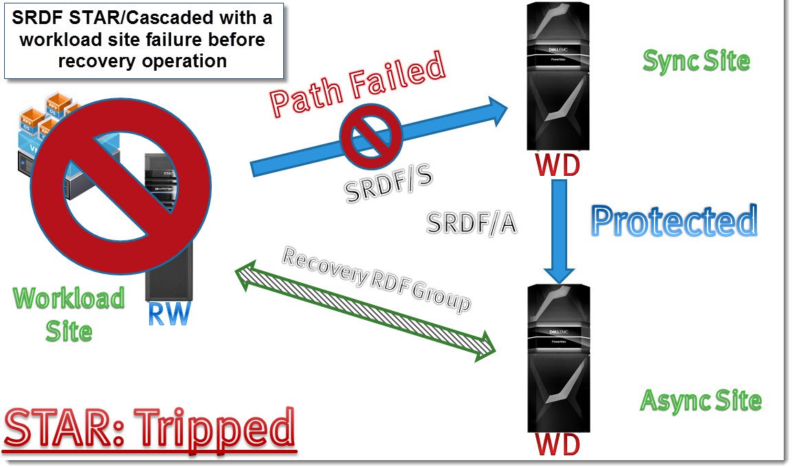
In a complete failure of the protected site, the Asynchronous site remains protected while the Synchronous site enters the “PathFail” state. Figure 150 schematically depicts a Cascaded SRDF/Star environment before recovery when it has experienced a complete protected site failure.
Figure 150. Cascaded SRDF/Star with workload site failure
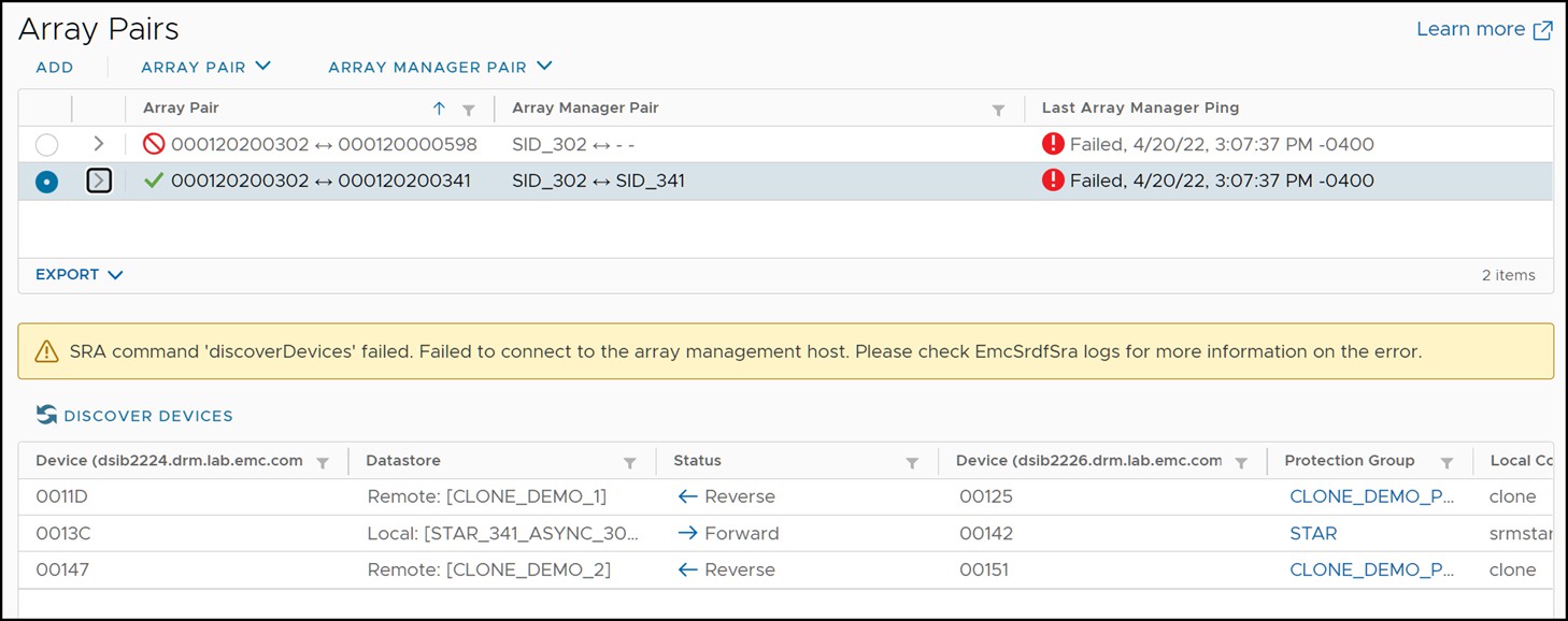
Since the entire workload site failed in this scenario, the array manager will not be able to update its information and the pairs screen may not show the correct information for all device pairs as it will show the last known state. This is due to the fact that the protected side Solutions Enabler server is down and the protected side array information cannot be retrieved. Notice that the arrays cannot be pinged, and the SRA warns it cannot discover devices. An example of this can be seen in Figure 151.
Figure 151. Failed device discovery due to off-line protected site Solutions Enabler server
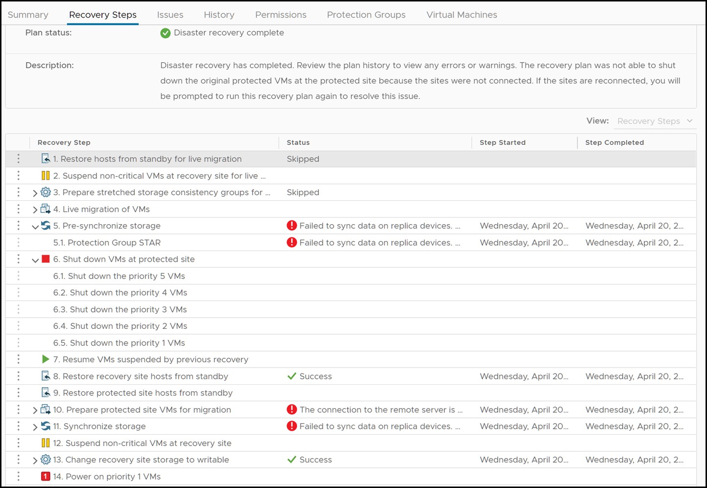
To recover the virtual machines on the surviving site, the “Recovery” link should be selected. Since the protected site is completely down the “Disaster recovery” mode is the only available option to choose, even if Planned migration is offered. The SRA does not, in principle, act any differently if the “Disaster recovery” mode is chosen as compared to “Planned migration”. The SRA will still attempt all operations as it would during a migration and return success or failure. The difference is that SRM will not fail the recovery plan on reception of a failed operation by the SRA. In the case of a protected site complete failure all steps involving the protected site will accordingly fail. Figure 152 shows a recovery plan that has been executed when the protected site has experienced a complete failure and the steps that will fail because of it.
Figure 152. Recovery plan execution during a complete protected site failure
Disaster Recovery to the Synchronous site with Cascaded SRDF/Star
The SRDF SRA recovers Cascaded SRDF/Star environments in a different way than it recovers Concurrent SRDF/Star environments when prompted by a protected site disaster. After attempting to and failing to switch the SRDF/Star Workload site to the Sync target, the SRA will then perform a reconfiguration of the Cascaded setup to turn it into a Concurrent environment. The reason for this is that if the Cascaded environment is just switched, so that the previous Sync site is the workload site, it will attempt to connect the new Sync site. Since the newly designated Sync site is the failed previously designated Workload site this operation would fail. Accordingly, since Cascaded requires the Synchronous site to be connected before the Async site can be connected (when the workload site is at the primary or secondary site), the Async site cannot be connected. Therefore no remote protection will be possible until the Sync site is back up. This is an unacceptable situation for most customers who are using 3-site replication. The solution to this problem is to reconfigure to Concurrent SRDF/Star. Concurrent SRDF/Star does not have this dependency, and either site can be connected and protected regardless to the state of the other site. Therefore in a situation where the protected site fails, the SRDF SRA will reconfigure the Cascaded SRDF/Star environment into a Concurrent SRDF/Star one.
Figure 153 depicts the final state of a Cascaded SRDF/Star environment which has been reconfigured into Concurrent SRDF/Star after disaster recovery to the secondary (sync) site.
Figure 153. Cascaded SRDF/Star reconfigured into Concurrent SRDF/Star
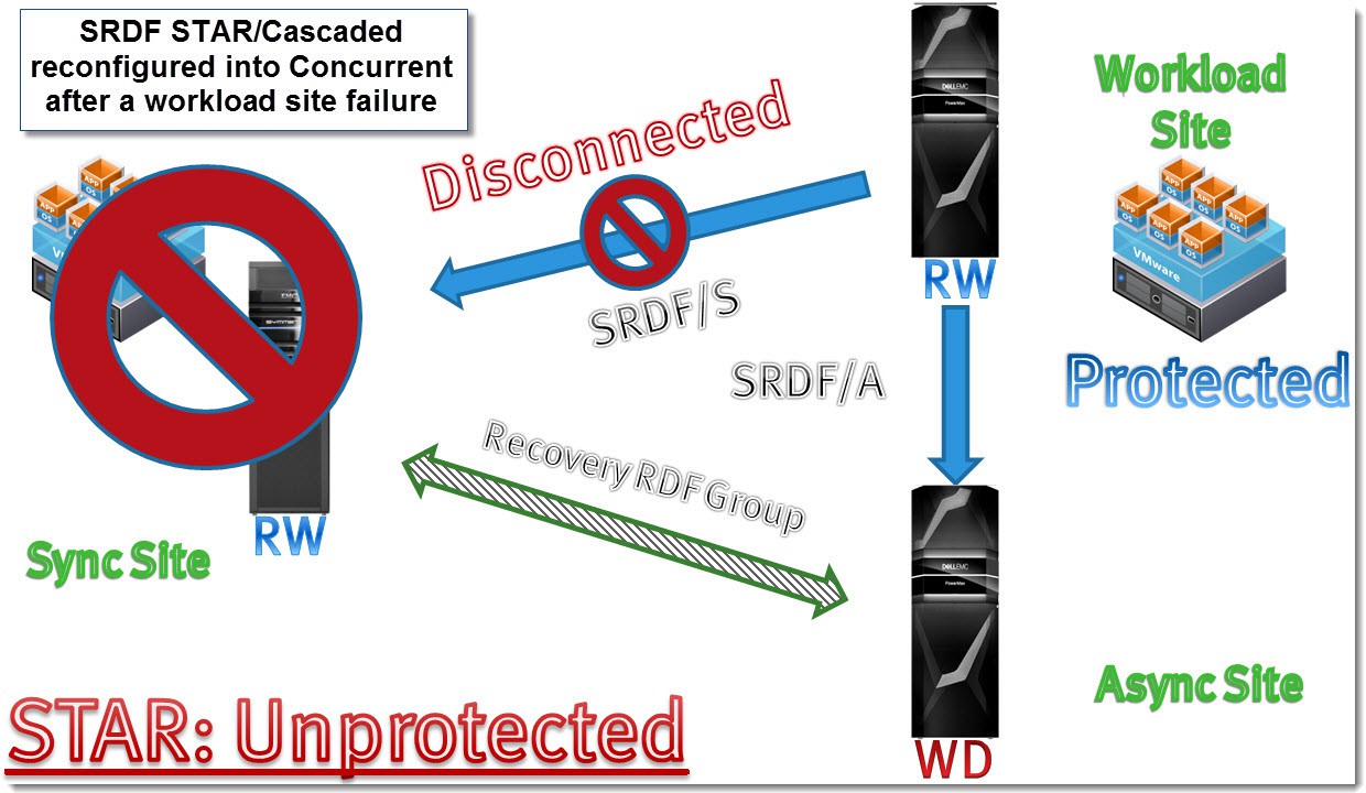
Table 26 shows the process steps taken by the SRDF SRA when recovering a Cascaded SRDF/Star setup with the workload site down.
Table 26. Cascaded SRDF/Star recovery to Sync site workflow
SRDF SRA step #
Step detail
Resulting SRDF/Star state
Site A after step
Site B after step
Site C after step
1
State before failover
Tripped
Workload
PathFail
Protected
2
Check if MSC cleanup is needed and perform a symstar cleanup on affected site. Required cleanup is denoted by the path being in the “Pathfail CleanReq” state
Tripped
Workload
PathFail
Protected
3
[OPTIONAL] Create recovery site gold copy
Tripped
Workload
PathFail
Protected
4
Perform a disconnect trip on site C.
Tripped
Workload
PathFail
PathFail
5
Switch Workload site to site B with “keep data” set to site B
Unprotected
Disconnected
Workload
Disconnected
6
Attempt to protect site A (will fail)
Unprotected
Disconnected
Workload
Disconnected
7
Attempt to protect site C (will fail)
Unprotected
Disconnected
Workload
Disconnected
8
Perform a SRDF/Star reconfiguration from Cascaded to Concurrent
Unprotected
Disconnected
Workload
Disconnected
9
Attempt to protect site A (will fail)
Unprotected
Disconnected
Workload
Disconnected
10
Connect site C
Unprotected
Disconnected
Workload
Connected
11
Protect site C
Unprotected
Disconnected
Workload
Protected
12
Attempt to enable SRDF/Star (will fail)
Unprotected
Disconnected
Workload
Protected
13
[OPTIONAL] Add R2 devices to storage group
Unprotected
Disconnected
Workload
Protected
Disaster Recovery to the Asynchronous site with Cascaded SRDF/Star
The disaster recovery workflow for recovery to the asynchronous site in Cascaded SRDF/Star is a somewhat more straight-forward process as compared to recovery to the synchronous target site. A reconfiguration is not required and the SRDF topology can remain in a Cascaded configuration (albeit still not completely protected).
When the workload site completely fails (storage and compute) recovery can be initiated to the tertiary/asynchronous target site of the Cascaded SRDF/Star configuration (site C). Site B and site C continue to function properly and the links between them remain up. Table 27 shows the workflow to recover to the asynchronous site.
Table 27. Cascaded SRDF/Star recovery to Async site workflow
SRDF SRA
step #
Step detail
Resulting SRDF/Star state
Site A after step
Site B after step
Site C after step
1
State before failover
Tripped
Workload
PathFail
Protected
2
Check if MSC cleanup is needed and perform a symstar cleanup on affected site. Required cleanup is denoted by the path being in the “Pathfail CleanReq” state
Tripped
Workload
PathFail
Protected
3
[OPTIONAL] Create recovery site gold copy
Tripped
Workload
PathFail
Protected
4
Perform a disconnect trip on site C.
Tripped
Workload
PathFail
PathFail
5
Switch Workload site to site C with “keep data” set to site B
Unprotected
Disconnected
Connected
Workload
6
Attempt to connect site A (will fail)
Unprotected
Disconnected
Connected
Workload
7
Protect site B
Unprotected
Disconnected
Protected
Workload
8
[OPTIONAL] Add R2 devices to storage group
Unprotected
Disconnected
Protected
Workload
[1] Disaster recovery mode also tolerates other SRDF/Star states, and thesestates are discussed in the ensuing section.
[2] State may be “Pathfail” or “Pathfail CleanReq” depending on the state of MSC. The SRA will perform a cleanup if the latter is the case.
[3] State may be “Pathfail” or “Pathfail CleanReq” depending on the state of MSC. The SRA will perform a cleanup if the latter is the case.
[4] Disaster recovery mode also tolerates other SRDF/Star states, but these states are discussed in the ensuing section.