
Expandable modular architecture: PowerMax Brick
Expandable modular architecture: PowerMax Brick
-
PowerMax configurations consist of modular building blocks called PowerMax Bricks (Bricks). The modular Brick architecture reduces complexity and allows for easier system configuration and deployment. This architecture also allows the system to scale while continuing to deliver predictable high performance.
There are two types of Bricks available for PowerMax:
- The open systems Brick supports configurations with Fibre Channel, FC-NVMe, or iSCSI connectivity with FBA device formatting. The Brick also can be configured for file storage using embedded NAS.
- The mainframe zBrick supports configurations with FICON connectivity and CKD device formatting.
Note: In this document, the term Brick is used when discussing features and functions applicable to both the open systems and the mainframe. When discussing features specific to mainframe, the term zBrick is specifically called out.
The initial system Brick includes a single engine consisting of two directors, two system power supplies (SPS), and two 24-slot 2.5” NVMe Drive Array Enclosures (DAE24) pre-configured with an initial total usable capacity.
The Brick concept allows PowerMax to scale up and scale out. Customers can scale up by incrementally adding Flash Capacity Packs. Each Flash Capacity Pack for the PowerMax 8000 has 13 TBu or 15 TBu of usable storage, and either 11 TBu, 13 TBu, or 15 TBu for the PowerMax 2000 model, depending upon the RAID protection type selected. PowerMax scales out by aggregating up to two Bricks for the PowerMax 2000, and up to eight for the PowerMax 8000. Scaling out a PowerMax system by adding additional Bricks produces a predictable, linear performance improvement regardless of the workload.
Note: For detailed information about available PowerMax Brick configurations, see the PowerMax Family Specification Sheet.
Engines
The core of the Brick is the engine. The engine is the central I/O processing unit, redundantly built for high availability. Each Brick consists of:
- Redundant directors that contain multi-core CPUs and memory modules
- Interfaces to universal I/O modules, such as front-end, back-end, InfiniBand, and flash I/O modules
The communication backbone of the Brick is the trusted Dynamic Virtual Matrix Architecture. Fundamentally, the virtual matrix enables inter-director communications over redundant internal InfiniBand fabrics. The InfiniBand fabric provides a foundation for a highly scalable, extremely low latency, and high-bandwidth backbone which is essential for an all flash array. This capability is also essential for allowing the PowerMax to scale upwards and scale outwards in the manner that it does.
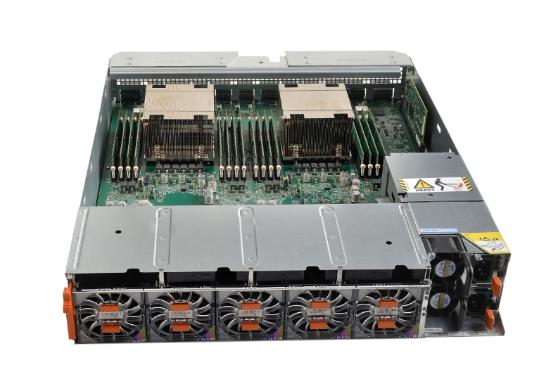
Figure 2. Brick engine director
Brick CPU core configurations
Each Brick engine has two directors, with each director having dual CPU sockets which support multi-core, multi-threaded Intel processors. The following table details the engine CPU core layout for each PowerMax model:
Table 4. Brick engine CPU cores
PowerMax model
Engine CPU type
CPU cores
Cores per Brick engine
Max cores per system
PowerMax 2000
Dual Intel Broadwell, 12 core, 2.5 GHz
24
48
96 (2 Bricks max.)
PowerMax 8000
Dual Intel Broadwell, 18 core, 2.8 GHz
36
72
576 (8 Bricks max.)
The Brick engine uses a core pooling mechanism which can dynamically load-balance the cores by distributing them to the front end, back end, and data services (such as SRDF, eNAS, and embedded management) running on the engine. The core pools can be tuned to shift the bias of the pools at any time to front-end heavy or back-end heavy workloads to further optimize the solution for a specific use case.
Note: Due to the advanced cooling dynamics of the PowerMax engine, the Intel CPUs primarily run in Turbo mode, providing additional performance capabilities.
Brick cache configurations
Every director has 16 memory slots which can be populated with 32 GB and 64 GB DDR4 DIMMS to achieve up to 1 TB cache per director (2 TB cache maximum per Brick engine).
Table 5. Brick cache configurations
PowerMax model
Cache per Brick
Max cache per system
PowerMax 2000
512 GB, 1 TB, 2 TB
4 TB (2 Bricks max.)
PowerMax 8000
1 TB or 2 TB
16 TB (8 Bricks max.)
On single-engine PowerMax 2000 systems, cache is mirrored within the engine across the directors. This is also true for multi-engine PowerMax 2000 systems and single-engine PowerMax 8000 systems. On multi-engine PowerMax 8000 systems, cache is mirrored across directors in different engines for added redundancy.
Both the PowerMax 2000 and PowerMax 8000 can support engine configurations with differing cache sizes (mixed cache). For dual-engine PowerMax 2000 models, the system can use engines with different cache sizes between the engines which are one cache size smaller or larger than the other engine in the system. For example, cache on engine 1 can be 1 TB while the cache on engine 2 is 512 GB. This would yield a total cache size of 1.5 TB for the system. Valid mixed cache configurations for the PowerMax 2000 are shown in the following table:
Table 6. Supported PowerMax 2000 mixed cache configurations
Number of ricks in system
Smallest engine cache size
Largest engine cache size
Total system cache
2
512 GB
1 TB
1.5 TB
2
1 TB
2 TB
3 TB
Mixed cache configurations are available on the PowerMax 8000; but require a minimum of four Bricks or zBricks in the system. The following table details the supported mixed cache configurations available for the PowerMax 8000:
Table 7. Supported PowerMax 8000 mixed-cache configurations
Number of Bricks in system
Smallest engine cache size
Largest engine cache size
Total system cache
4
2 engines at 1 TB
2 engines at 2 TB
6 TB
5
2 engines at 1 TB
3 engines at 2 TB
8 TB
5
3 engines at 1 TB
2 engines at 2 TB
7 TB
6
2 engines at 1 TB
4 engines at 2 TB
10 TB
6
4 engines at 1 TB
2 engines at 2 TB
8 TB
7
2 engines at 1 TB
5 engines at 2 TB
12 TB
7
5 engines at 1 TB
2 engines at 2 TB
9 TB
7
3 engines at 1 TB
4 engines at 2 TB
11 TB
7
4 engines at 1 TB
3 engines at 2 TB
10 TB
8
2 engines at 1 TB
6 engines at 2 TB
14 TB
8
6 engines at 1 TB
2 engines at 2 TB
10 TB
8
4 engines at 1 TB
4 engines at 2 TB
12 TB
Note: Cache within an engine can be upgraded (capacity added), but cache cannot be downgraded (capacity removed).
PowerMaxOS
Each PowerMax engine comes with PowerMaxOS 5978 installed. PowerMaxOS is derived from the trusted and proven HYPERMAX OS used by the legacy VMAX3 and VMAX All Flash arrays; however, PowerMaxOS has been re-written to take advantage of NVMe architectures. PowerMaxOS continues to provide industry-leading high availability, I/O management, quality of service, data integrity validation, data movement, and data security within an open application platform. PowerMaxOS uses a real-time, non-disruptive storage hypervisor that manages and protects embedded services by extending high availability to services that traditionally would have run external to the array. The primary function of PowerMaxOS is to manage the core operations performed on the array, which include:
- Processing I/O from hosts
- Implementing RAID protection
- Optimizing performance by allowing direct access to hardware resources
- Managing and monitoring the system
Drive array enclosures
Each Brick comes with two 24-slot, dual-ported, 2.5” PCIe NVMe DAEs (DAE24). These DAEs use redundant, hot-swappable Link Control Cards (LCCs) which provide PCIe I/O connectivity to the NVMe flash drives. Aside from redundant LCCs, the DAE24 features redundant power supplies with separate power feeds, providing N+1 power and cooling, resulting in an energy-efficient consumption of up to 25 watts per drive slot. The DAE24 is 2U high and 19” deep.

Figure 3. Brick NVMe DAE24
The directors are connected to each DAE through a pair of redundant back-end I/O modules. The back-end I/O modules connect to the DAEs at redundant LCCs. Each connection between a back-end I/O module and an LCC uses an independent cable assembly. Within the DAE, each NVMe drive has two ports, each of which connects to one of the redundant LCCs.
The dual-initiator feature ensures continuous availability of data in the unlikely event of a drive management hardware failure. Both directors within an engine connect to the same drives using redundant paths. If the sophisticated fencing mechanisms of PowerMaxOS detect a failure of the back-end director, the system can process reads and writes to the drives from the other director within the engine without interruption.
Drive options and configurations
Both PowerMax 2000 and PowerMax 8000 support 1.92 TB, 3.84 TB, 7.68 TB, and 15.36 TB NVMe flash drive capacities as well as 750 GB and 1.5 TB SCM drives. All the drive sizes are 2.5” and feature a dual ported U.2 form factor PCIe interface. These drive capacities can be intermixed on the system.
Table 8. PowerMax family supported capacity specifications
PowerMax 2000
PowerMax 8000
Capacity and drives
Max Capacity per Array (Open) 1
1.2 PBe
4.5 PBe
Base Capacity per Brick (Open)
13.2 TBu 3
54 TBu
Base Capacity per Brick (mainframe)
N/A
13.2 TBu
Incremental Flash Capacity Packs 5
13.2 TBu 3
13.2 TBu
Max Drives per Brick
44 Usable + spare(s)
32 Usable + spare(s)
Max Drives per Array
962
288
NVMe drives
NVMe Drives Supported (2.5”)
1.92 TB, 3.84 TB, 7.68 TB, 15.36 TB
1.92 TB, 3.84 TB, 7.68 TB, 15.36 TB
SCM drives
SCM Drives Supported (2.5”)
750 GB, 1.5 TB
750 GB, 1.5 TB
BE Interface
NVMe over PCIe
NVMe over PCIe
RAID Options Supported
RAID 5 (7+1) (default)
RAID 5 (3+1)
RAID 6 (6+2)
RAID 1 (Mirrored) 4,5
RAID 5 (7 +1) (default)
RAID 6 (6+2)
RAID 1 (Mirrored) 4,5
1 Max capacity per array based on over provisioning ratio of 1.0.
2 192 drives can be supported in a single cabinet when two systems are packaged in the same rack.
3 13.2 TBu Brick and Flash capacity pack usable capacities are based on RAID 5 (7+1). 11.3 TBu base capacity and Flash capacity pack increments possible with RAID 5 (3+1) on PowerMax 2000.
4 RAID 1 will be offered on both PowerMax 2000 and PowerMax 8000 systems post GA of the 3Q 2020 release. Contact your local Dell Technologies sales team for more details and availability.
5 Incremental capacity packs under RAID 1 are 15.0TBu minimum for both the PowerMax 2000 and PowerMax 8000.
Note: For detailed information about available PowerMax Brick drive configurations, see the PowerMax Family Specification Sheet.
PowerMax Storage Resource Pools overview
In PowerMax, all physical storage capacity is combined into Storage Resource Pools (SRPs). At the lowest levels, SRPs consist of Disk Groups which contain of a collection of hard drives sharing the same technology and performance characteristics. The hard drives in each disk group are split into individual back-end data device segments called TDATs. The TDATs are placed into an associated Storage Tier.
An SRP is the collection of the total capacity of all its Storage Tiers – regardless of the underlying disk technology which the storage tiers are associated with. This physical capacity stored within an SRP is referred to its usable capacity (TBu). This usable capacity is accessed by hosts using thinly provisioned front-end storage devices called TDEVs. TDEVs are virtual representation of the SRP physical capacity which also considers overprovisioning and data reduction efficiencies. For example, an array with a single SRP which has 26 TBu, could be provisioned for 78 TB of host facing TDEV capacity when a data reduction ratio of 3:1 is applied. This 78 TB of virtualized host facing TDEV capacity is referred to be the effective capacity (TBe) of the SRP. When a PowerMax is sized, both the usable capacity and effective capacity are considered. The total usable capacity (TBu) is the primary driver for sizing hard-drive-layout configurations. The effective capacity (TBe) is a primary driver when sizing PowerMax cache.
Host provisioned TDEVs to are placed into a storage group and assigned a Service Level. When a host writes application data to its provisioned TDEVs, this data is distributed across all the storage tiers within the SRP. Which storage tier the data is placed on within the SRP is governed by the Automated Data Placement (ADP) utility. ADP uses the PowerMax internal machine learning engine to employ predictive analytics and pattern recognition algorithms to place the data at the optimal physical location to ensure that the response time requirements for the assigned service level are met.
The following diagram illustrates the key components involved with a PowerMax SRP:

Figure 4. Typical components found with a PowerMax SRP with example of disk-group RAID-protection schemes
Note: The following points are specific notes regarding PowerMax SRPs.
- A PowerMax 8000 can now be configured so that both mainframe CKD and Open Systems FBA data can share a single SRP.
- PowerMax 8000 systems that will offer mixed FBA and CKD capacity must be born as a mixed system in the factory. CKD capacity cannot be added to an existing FBA system and conversely.
- Only a single RAID protection scheme can be used within the PowerMax SRP. The use of multiple RAID protection schemes is not supported within the PowerMax SRP.
- Dell Technologies recommends that all PowerMax systems be configured as a single SRP system so that customer data has access to the maximum amount of system resources as possible.
- While multiple PowerMax SRP systems are supported through RPQ, we do not recommend the use of multiple SRPs in a single PowerMax system for performance and manageability reasons.
Configuring SCM drives on PowerMax
SCM drives can be used on both the PowerMax 2000 and PowerMax 8000 systems. A way to think of NVMe connected SCM drives is as an extension of physical server memory where the application data stored on these SCM drives requires the highest levels of performance - typically reserved for server-based Non-Volatile DIMM (NVDIMM). While NVMe SCM does not provide the same levels of performance as NVDIMM, its economics from a $/GB and $/IOPS perspective make it an attractive lower cost alternative to server based NVDIMM for in memory applications such as SAP HANA.
PowerMax systems using SCM drives can be configured to have the SCM drives intermixed with traditional NAND flash drives in the DAEs. On these intermixed systems (known as “SCM as a Tier” systems – as shown in Figure 4), the devices carved from the SCM drives will be placed into “Tier 0” where the most active data on the system will reside.
Also, to ensure the highest levels of performance on the intermixed systems, the data on the SCM tier 0 is never compressed; however, it can be deduped. As said earlier, the system uses ADP’s predictive analytics and pattern recognition algorithms to ensure that the data is placed on and removed from Tier 0 in the most timely and efficient manner. Storage groups assigned the “Diamond” service level will be given priority for Tier 0 placement. Storage groups assigned as either “Silver” or “Bronze” are not eligible for Tier 0 placement and will always reside on NAND flash.
Note: The following are some other general configuration notes regarding SCM-as-a-tier PowerMax arrays.
- For optimum cost per performance, Dell Technologies recommends that the total usable capacity (TBu) of SCM Tier 0 be between 3% – 12% of the desired effective capacity (TBe) of the system.
- Up to three RAID groups of SCM (PowerMax 8000) and 4 RAID groups of SCM (PowerMax 2000) can be configured per engine as a tier 0.
- All engines must be configured identically with respect to SCM, for I/O balance (if an engine is configured with one R5 7+1 SCM RAID group, then all other engines in the system must be configured with one R5 7+1 SCM RAID group).
- While multiple SRPs are supported on PowerMax, only one SRP can contain SCM and this SRP must see the SCM storage as a tier (the SRP cannot be 100% SCM).
- Data is never compressed in SCM tier unless the system is comprised of 100% SCM drives.
- Data in SCM may be part of a dedupe set.
- Mixed SCM configurations using 750 GB and 1.5 TB SCM Drives are supported.
- SCM storage can use either RAID 1 (Mirrored), RAID 5 (3+1 and 7+1), RAID 6 (6+2) protection on PowerMax 2000.
- SCM storage can use either RAID 1 (Mirrored), RAID 5 (7+1) or RAID 6 (6+2) protection on PowerMax 8000.
- SCM storage must be of the same RAID type of the NAND flash in the system.
- Systems with SCM are configured with one SCM spare per engine. The SCM spare must match the largest capacity of SCM drive in the system.
PowerMax can also be configured as a 100% SCM system. In these systems (known as “SCM Bricks”), data can be both compressed and deduplicated. Activity-based compression rules apply where approximately 20% of the effective capacity of the SCM Brick is left uncompressed. The minimum capacity and incremental capacity configuration for an SCM Brick is 21 TBu consists of 17 (16 data + 1 spare) x 1.5 TB SCM drives configured into two RAID 5 (7+1) RAID groups. RAID 5 (7+1) protection using 1.5 TB drives is the only supported RAID configuration for SCM Bricks. SCM Bricks can have only a single SRP which consists of 100% SCM drives. NAND flash drives cannot be added to an SCM Brick.
The following figure shows the key differences between the two types of PowerMax SCM configurations:

Figure 5. Supported PowerMax SCM configurations
PowerMax Universal Sparing
PowerMaxOS supports Universal Sparing to automatically protect a failing drive with a spare drive. Universal Sparing increases data availability of all volumes in use without loss of any data capacity, transparently to the host, and without user intervention.
When PowerMaxOS detects a drive is failing, the data on the faulty drive is copied directly to a spare drive attached to the same engine. If the faulty drive has failed, the data is rebuilt onto the spare drive through the remaining RAID members. When the faulty drive is replaced, data is copied from the spare to the new drive.
PowerMax systems have one spare drive for each drive type in each engine. The spare drives reside in dedicated DAE slots. If the system is a mixed NAND Flash and SCM system, then it will need one spare for the NAND Flash drives and one for the SCM drives. SCM Bricks only need one spare SCM drive. The spare drive type is the same as the highest capacity and performance class as the other drives in the engine.
For example, if a system uses both 3.84 TB and 7.68 TB NAND Flash drives in the configuration, only one 7.68 TB drive needs to be configured as a spare as it can replace either the 3.84 TB or 7.68 TB drives.

Figure 6. Universal Sparing example
PowerMax Smart RAID
PowerMax uses an active/active RAID group accessing scheme called Smart RAID. This allows RAID groups to be shared across directors, giving each director active access to all drives on the Brick or zBrick.

Figure 7. PowerMax Smart RAID
The use of Smart RAID on PowerMax provides customers with performance benefits as both directors on an engine can drive I/O to all the flash drives. This creates balanced configurations in the system regardless of the number of RAID groups. Smart RAID also allows for increased flexibility and efficiency as customers can order PowerMax 8000 systems with a single RAID group allowing for a minimum of 9 drives per engine with RAID 5 (7+1) and 1 spare or RAID 6 (6+2) and 1 spare; 2 drives and one spare with RAID 1 (Mirrored); and 5 drives per system for a PowerMax 2000 with RAID 5 (3+1) and 1 spare. This leaves more drive slots available for capacity upgrades in the future. When the system is scaled up, customers have more flexibility because flash capacity pack increments can be a single RAID group.
PowerMax 2000 DAE connectivity and drive allocation schemes
Smart RAID and Universal Spare allow flexible connectivity and drive allocation schemes to occur with the PowerMax DAE. With the PowerMax 2000, each engine director has two NVMe I/O Modules. Each I/O module has two redundant paths. One path connects to either Link Control Card (LCC) A or LCC B in DAE 1 while the other path connects to either LCC A or LCC B in DAE 2. Each path from the NVMe I/O module to the LCC is a four lane PCIe Gen3 connection (4 GB/sec).
The following diagrams detail the DAE connectivity layout and drive allocation schemes for the PowerMax 2000.

Figure 8. PowerMax 2000 single engine DAE connectivity

Figure 9. PowerMax 2000 dual engine DAE connectivity
The PowerMax 2000 can use the RAID 1 (Mirrored), RAID 5 (3+1), RAID 5 (7+1), or RAID 6 (6+2) protection schemes. Only one RAID protection scheme can be applied on the system. When populating the PowerMax 2000 DAEs, each engine requires a minimum of 1 RAID group including spare drives. There are two spare drive slots in a PowerMax 2000 system (slot 24 in each DAE); however, there can be only one spare drive for each Brick. When populating the drives into the system, the drives are alternately placed in DAE1 and DAE2.

Figure 10. PowerMax 2000 DAE drive slot allocations for a single Brick

Figure 11. PowerMax 2000 DAE drive slot allocations for a dual Brick
The maximum number of usable drives which can be used with a single PowerMax 2000 Brick is 40 plus 1 spare drive for RAID 5 (7+1) or RAID 6 (6+2) configurations; and 44 usable drives plus 1 spare using a RAID 5 (3+1) configuration or RAID 1 (Mirrored).
Note: See the following list for details on PowerMax 2000 DAE and drive allocation.
- Mixed drive sizes can be used in the system for both NAND Flash and SCM. Drive sizes need to be one size increment apart (for example, 1.92 TB and 3.84 TB, or 3.84 TB and 7.68 TB).
- Only one spare drive per Brick is required. The spare needs to be the same size as the largest drive size used in the system.
- Every PowerMax 2000 system requires at least one RAID group.
- DAEs are not shared by the engines in a dual Brick PowerMax 2000 configuration.
- RAID groups are associated with a single Brick engine.
- Only one RAID protection scheme per PowerMax 2000 system is allowed.
- RAID 5 (3+1) requires a minimum of 4 drives plus 1 spare.
- RAID 5 (7+1) and RAID 6 (6+2) require a minimum of 8 drives plus 1 spare.
- RAID 1 (Mirrored) requires a minimum of 2 drives plus 1 spare.
PowerMax 8000 DAE connectivity and drive allocation schemes
The PowerMax 8000 uses Smart RAID and Universal Sparing to achieve the densest possible engine and flash drive capacity configurations in the industry. To achieve these high densities, the PowerMax 8000 uses different DAE connectivity and drive allocation schemes from those used in the PowerMax 2000. In systems using a single Brick, the DAE connectivity is like the PowerMax 2000; however, drive slots 15 to 24 in the DAE 2 are reserved for future scale out of a second Brick.
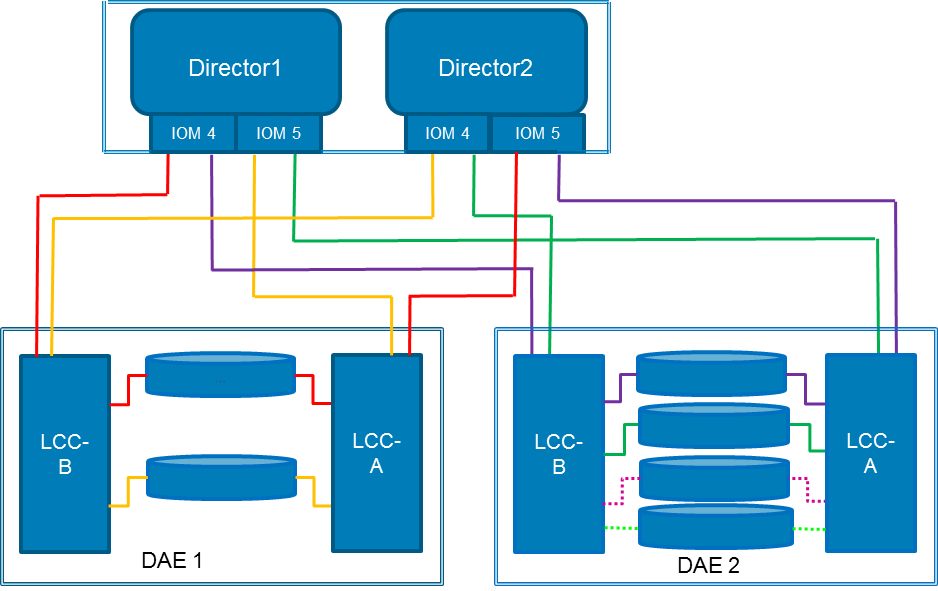
Figure 12. PowerMax 8000 single engine DAE connectivity
When a second Brick is added into the system, a third DAE is also added, and drive slots 15 to 24 of the DAE 2 on the first Brick can be populated and accessed by the second Brick. This is made possible as the 3rd and 4th Mini-SAS HD PCIe I/O ports on the LCCs in DAE 2 are used by the second Brick as shown in the following diagram:
Figure 13. PowerMax 8000 dual e
 ngine DAE connectivity
The PowerMax 8000 can use the RAID 1 (Mirrored), RAID 5 (7+1), or RAID 6 (6+2) protection schemes. Like the PowerMax 2000, only one RAID protection scheme can be applied on the system, even on systems that have multiple SRPs. When populating the PowerMax 8000 DAEs, each Brick engine must have at least 1 RAID group including spare drives. For single Brick configurations, drives can be added in slots 1 to 24 of DAE 1, and in slots 1 -12 on DAE 2. Slots 13 and 14 in DAE 2 are reserved for spare drives. This results in a maximum of 32 usable drive slots plus spares in a single Brick system. As with the PowerMax 2000, only one spare drive is required per Brick.

Figure 14. PowerMax 8000 drive slot allocations for a single Brick
A third DAE (DAE 3) is added to the system when adding a second Brick into the system. The second Brick uses slots 1 to 24 of DAE 3 and shares DAE 2 with the first Brick, using slots 17 to 24 in DAE 2. Slots 15 and 16 in DAE 2 are reserved for the second Brick spare drives. The following figure shows how drive slots are allocated in a dual Brick PowerMax 8000 system:

Figure 15. PowerMax 8000 drive slot allocations for dual Bricks
A PowerMax 8000 can be configured for open systems, mainframe, or mixed open systems and mainframe workloads.
Note: The following list includes PowerMax 8000 DAE and drive allocation notes.
- Every PowerMax 8000 system requires a minimum of one RAID group.
- Only one RAID protection scheme is allowed per PowerMax 8000 system
- Mixed drive sizes can be used in the system for both NAND Flash and SCM. Drive sizes need to be one size increment apart (for example, 1.92 TB and 3.84 TB, or 3.84 TB and 7.68 TB).
- Only one spare drive per Brick is required. The spare needs to be the same size as the largest drive size used in the system.
- RAID groups are associated to a single Brick engine.
- RAID 5 (7+1) and RAID 6 (6+2) protection schemes require a minimum of 8 drives plus 1 spare. RAID 1 (Mirrored) requires a minimum of 2 drives plus 1 spare
- Every even-numbered Brick will share a DAE with the previous odd-numbered Brick.
- Odd-numbered Bricks will have 24 plus 12 drives. Even-numbered Bricks will have 24 plus 10 drives.
Flash optimization
All flash-based storage systems demand the highest levels of performance and resilience from the enterprise data storage platforms that support them. The foundation of a true all flash array is an architecture that can fully leverage the aggregated performance of modern high-density flash drives while maximizing their useful life. Many features are built into the architecture of PowerMax to maximize flash drive performance and longevity. This section discusses these features in detail.
Cache architecture and caching algorithms
PowerMax is built upon a very large, high-speed DRAM cache-based architecture, driven by highly complex and optimized algorithms. These algorithms accelerate data access by avoiding physical access to the back end whenever possible. Dell Technologies has spent many years developing and optimizing caching algorithms. The algorithms used by PowerMax optimize reads and writes to maximize I/Os serviced from cache and minimize access to back-end flash drives. The system also monitors I/O patterns and proactively populates cache based on access to increase the chances of cache hits.
Some of the techniques used by the cache algorithms to minimize disk access are:
- 100% of host writes are cached.
- More than 50% of reads are cached.
- Recent data is held in cache for long periods, as that is the data most likely to be requested again.
- Intelligent algorithms destage in a sequential manner.
PowerMax write amplification reduction
Write amplification must be properly controlled to ensure the longevity of NAND flash and SCM storage devices. Controlling write amplification is one of the greatest strengths of PowerMax and what truly sets it apart from its competitors. Aside from intelligent caching algorithms, which keep data in cache as long as possible, the PowerMax uses additional methods to minimize the number of writes to flash. These methods are:
- Write Folding – Write Folding avoids unnecessary drive I/Os when hosts rewrite to an address range. This rewritten data is simply replaced in cache and not repeatedly written to the drive. Write folding can reduce writes to the NAND flash and SCM drives by up to 50%.
- Write Coalescing – Write Coalescing merges subsequent small random writes from different times into one large sequential write. These larger writes to the storage drives align much better with the page sizes within the storage drive itself. Using write coalescing, PowerMax can take a highly random write host I/O workload and make it appear as a sequential write workload to the NAND flash and SCM drives.
- Advanced Wear Analytics – PowerMax also includes advanced drive wear analytics optimized for high capacity storage drives to make sure writes are distributed across the entire storage tier to balance the load and avoid excessive writes and wear to particular drives. Not only does this help manage the drives in the storage tier, but it also makes it easy to add and rebalance additional storage into the system.
All the write amplification reduction techniques used by PowerMax result in a significant reduction in writes to the back end, which in turn significantly increases the longevity of the NAND flash and SCM drives used in the array.
Boosting flash performance with PowerMaxOS FlashBoost
Dell Technologies is always striving to improve performance in its products. With every new hardware platform and release of software, the company makes strong efforts to remove potential bottlenecks which can impede performance in any way. One feature that Dell Technologies introduced and has made standard as a part of PowerMaxOS is FlashBoost.
FlashBoost maximizes PowerMaxOS efficiency by servicing read requests directly from the back-end flash drives. This approach eliminates steps required for processing I/O through global cache and reduces the latency for reads, particularly for flash drives. Customers with heavy read miss workloads residing on flash can see up to 100% greater IOPS performance. FlashBoost works with both NAND Flash and SCM storage.
Director slot layout and connectivity options
The Brick engine architecture uses a series of hot swappable modules that plug into slots in the engine directors. These modules include:
- Engine cooling fans and power supplies in slots accessible from the front of the engine director.
- I/O modules, management modules, and control stations in slots accessible from the rear of the engine director.
The following table describes the module components used in a Brick engine director:
Table 9. PowerMax engine director components
Director component
Quantity per director
Purpose
Power Supply
2
Provides redundant power to director.
Fan
5
Provides director cooling.
Management Module
1
Manage environmental functionality.
NVMe Flash I/O Module
Up to 4
The flash I/O modules use NVMe technology to safely store data in cache during the vaulting sequence (800 GB).
Front-end I/O Module
Up to 4
Provide front-end connectivity to the array. There are different types of front-end I/O modules that allow connectivity to various interfaces including Fibre Channel SCSI, Fibre Channel NVMe, iSCSI, FICON, SRDF, and embedded NAS (eNAS).
NVMe PCIe Back-end I/O Module
2
Dual-ported PCIe 4x Gen3 interface to the NVMe storage (8 GB/sec).
Data Reduction Module *
1
Performs inline data compression and deduplication, as well as SRDF compression.
Fabric I/O Module
1
Provides connectivity between directors. In multi-engine PowerMax 8000 systems, the fabric I/O modules are connected to an internal InfiniBand switch.
* An additional data reduction module is required for E2EE and will occupy a front-end I/O module slot.
The following diagram shows the director module layouts for the PowerMax 2000:
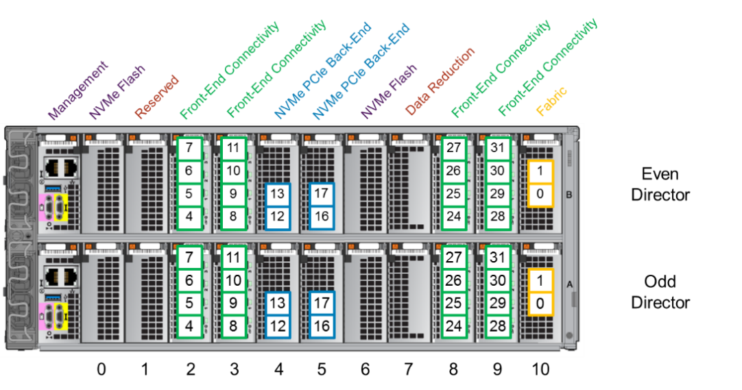
Figure 16. PowerMax 2000 director module layout by slot number
Both single-engine and multi-engine PowerMax 2000 systems use the same director module layout. Both configurations use two NVMe flash modules residing in slots 0 and 6 on each director. Slots 7 houses the data reduction module. Slots 2, 3, 8, and 9 are used for front-end connectivity modules. Slots 4 and 5 contain the NVMe PCIe back-end connectivity modules. Slot 10 houses the fabric modules. Slot 1 is reserved for future use.
The following diagrams detail the director module layouts for single-engine and multi-engine PowerMax 8000 systems:

Figure 17. PowerMax 8000 director module layout by slot number: Single-engine system

Figure 18. PowerMax 8000 director module layout by slot number: Multiple-engine system
Unlike the PowerMax 2000, there are differences in the director module layouts between single-engine and multi-engine PowerMax 8000 systems. Single-engine PowerMax 8000 systems use four NVMe Flash modules. These modules occupy director slots 0, 1, 6, and 7. The data reduction module resides in slot 9. Slots 2, 3, and 8 are used for front-end connectivity modules.
Multi-engine PowerMax 8000 systems use three NVMe flash modules, occupying slots 0, 1, and 6. The data reduction module occupies slot 7. This leaves an additional slot for a front-end connectivity module allowing multi-engine PowerMax 8000 systems to have four front-end connectivity modules, occupying director slots 2, 3, 8, and 9.
Note: The following list includes director slot and connectivity notes.
- For PowerMax 8000 systems that only had a single engine originally, the single-engine configuration of three slots available for front-end modules is applied to each additional engine added to the system when the system is scaled out. When additional engines are added to PowerMax 8000 systems that were originally multi-engine systems, these engines can have up to four slots available for front-end modules.
- On multi-engine systems, the compression module must use the same director slots on each engine.
- Data compression and deduplication are not available on the mainframe PowerMax 8000, but SRDF compression is available. On mainframe PowerMax 8000 systems (zBricks) which use SRDF compression only, place a compression module on the director with ports configured for SRDF. On single-engine configuration systems, place the SRDF compression module in slot 9; while on multi-engine configuration systems, place the SRDF compression module in slot 7.
Both the PowerMax 2000 and the PowerMax 8000 provide multiple front-end connections that implement several protocols and speeds. The following table highlights the various front-end connectivity modules available for a PowerMax system:
Table 10. Supported Brick front-end connectivity modules
Connectivity type
Module type
Number of ports
Mix with protocols
Supported speeds (Gbps)
Fibre Channel
32 Gbps FC
4
FC-NVMe / SRDF
8/16/32
Fibre Channel
16 Gbps FC
4
SRDF
4/8/16
SRDF
25 GbE
4
iSCSI
25
SRDF
10 GbE
4
iSCSI
10
iSCSI
25 GbE
4
SRDF
25
iSCSI
10 GbE
4
SRDF
10
FICON *
16 Gbps FICON
4
Single/Multi Mode
4/8/16
eNAS
10 GbE
2
None
10
eNAS
10 GbE (Copper)
2
None
10
eNAS Tape Backup
8 Gbps FC
4
None
2/4/8
* Supported on PowerMax 8000 only
Note: The following list includes other PowerMax connectivity notes.
- Each Brick engine has at least one front-end module pair (one front-end module per director).
- Since the number of front-end modules used in the Brick engine depends on the customer’s requirements, some director slots may not be used.
- Front-end modules for Fibre Channel support multi-mode (MM). Front-end modules for FICON support both multi-mode (MM) and single-mode (SM). Front-end modules for 25 GbE/10 GbE support only MM optics.
- 25 GbE front-end modules will not auto-negotiate to 10 GbE.