
Microsoft SQL Server Disaster Protection with Dell PowerFlex Replication
Network architecture
Network architecture
-
The following network diagram provides an overview of the architecture when a PowerFlex rack is deployed at both the source and target site, using PowerFlex asynchronous replication.
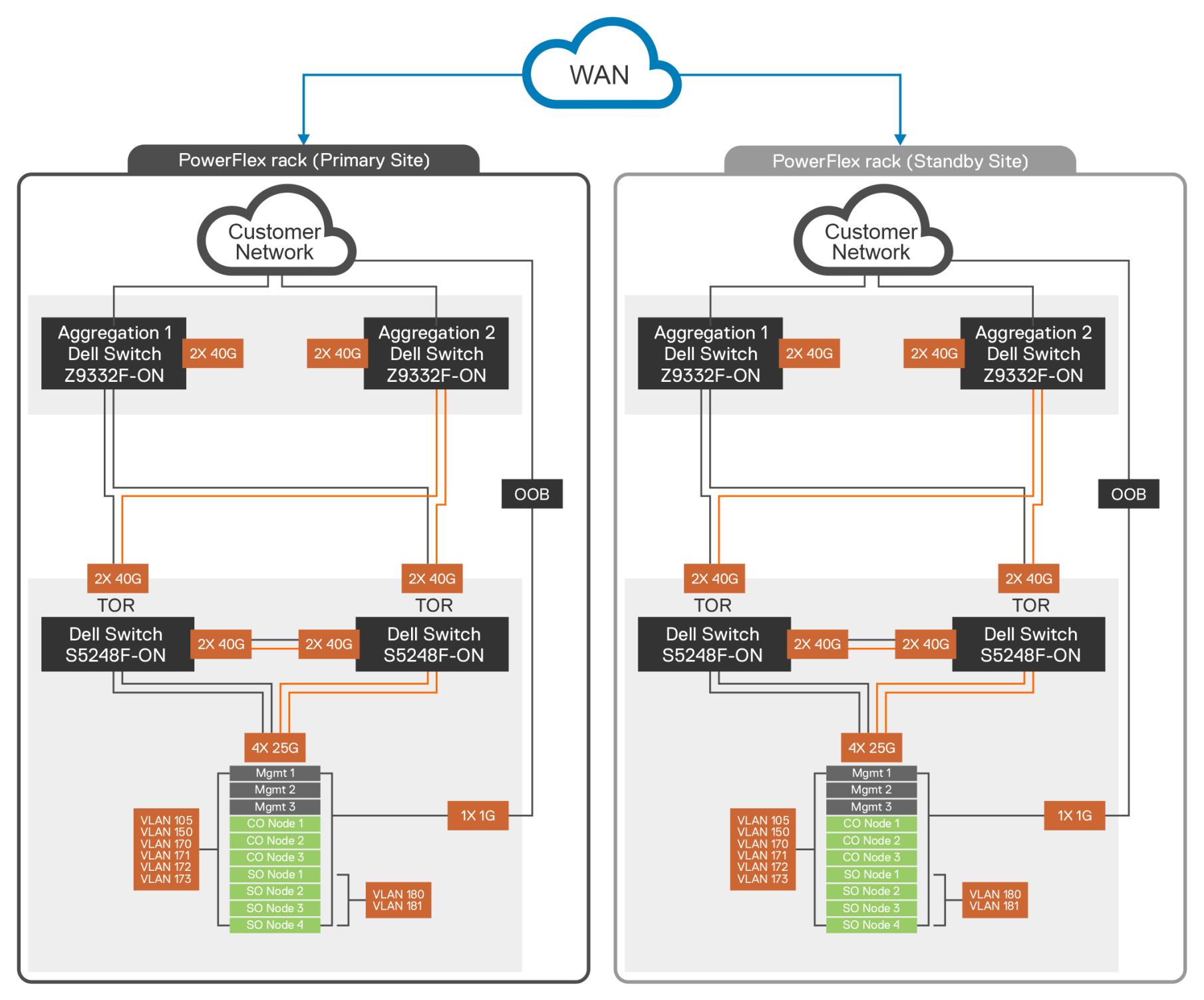
Figure 4. Network architecture of PowerFlex asynchronous replication
The following table contains the network details of each PowerFlex rack:
Table 2. PowerFlex networking details
Components
Description
Application Traffic
2 x 25 Gbps links
PowerFlex Storage Traffic
2 x 25 Gbps links
VLAN 105
Hypervisor Management
VLAN 150
PowerFlex Management
VLAN 151, 152, 153, 154
Data1 Network, Data2 Network, Data3 Network, Data4 Network
VLAN 160, 161
Replication Traffic Network