
PowerFlex rack
PowerFlex rack
-
For our use case, we deployed a PowerFlex rack, which includes the PowerFlex appliance in a cabinet that includes smart power delivery units and thermal sensors. The PowerFlex rack also comes with a white-glove deployment service that ensures a turnkey experience.
The PowerFlex rack supports bare-metal deployments, although a bare-metal deployment requires support preapproval.
In our PowerFlex rack, we used Dell EMC PowerEdge R840 servers for the storage pool. The Storage Data Server (SDS) is a service that runs on each server and is the broker for storage services, as shown in the following figure:
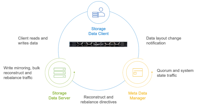
Figure 6. PowerFlex services communication
For this test, the PowerFlex rack had four storage nodes, each running the SDS service. We considered two flexible PowerFlex deployment options for this project. The first is a traditional two-layer SAN architecture in which applications use compute resources that are separate from the SAN resources, as shown in the following figure. This deployment option works well for applications that require fully dedicated CPU and memory for optimal performance or that work only in a traditional two-layer architecture.
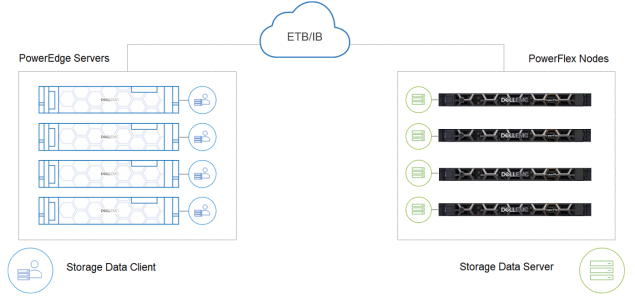
Figure 7. PowerFlex two-layer architecture
A single-layer deployment option, also called hyperconverged infrastructure (HCI), is a model where computes and storage reside on the same layer, as shown in the following figure. We used this model in our testing because the goal was to maximize consolidation. For example, our Big Data Cluster containers were sharing compute resources on the PowerFlex system. The HCI deployment option maximizes a customer’s investment through consolidation.
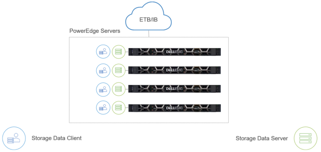
Figure 8. Single-layer (HCI) architecture
In our PowerFlex rack, we used four R840 servers, each running the SDS service. Thus, all four servers contributed to the storage pool for the Big Data Cluster. We configured each R840 with four Intel Xeon Gold 6140M CPUs, and each CPU had 18 cores, for a total of 72 cores. With hyperthreading enabled, 144 logical cores were available on each server.
Each server had eight 3.84 TB SSDs, for a total 30.72 TB of raw capacity, providing a storage configuration in which performance and capacity are well balanced. Because our focus is on how to take advantage of a Big Data Cluster, rather than on performance, we do not report on performance in this white paper.
Part of the PowerFlex rack includes controller nodes that run the Meta Data Manager (MDM) service. The controller nodes coordinate operations between the client (SDC) and storage nodes (SDS). For example, the controller nodes communicate with clients if the data layout changes and with the storage nodes for rebalancing activities. The MDM services ran across three PowerEdge R640 servers, as shown in the following figure:
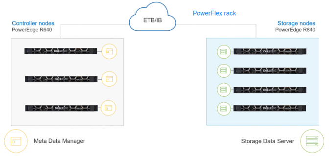
Figure 9. Controller nodes
The PowerFlex rack that we used for testing was designed for high availability (HA). The HA design starts with the RAID 1 mesh mirrored layout, which is shown in the following figure:
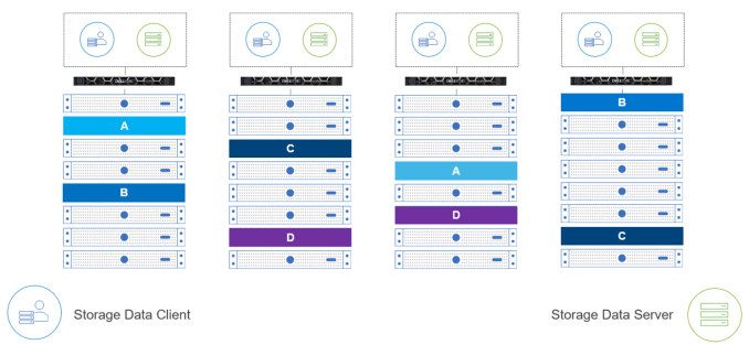
Figure 10. PowerFlex RAID 1 mesh example
With RAID 1 mesh mirrored protection, each data block is stored on two different SDS units. Ensuring that multiple copies of data reside on separate physical storage protects against a single drive failure, and, by extension, having copies of data across nodes protects against node failure.