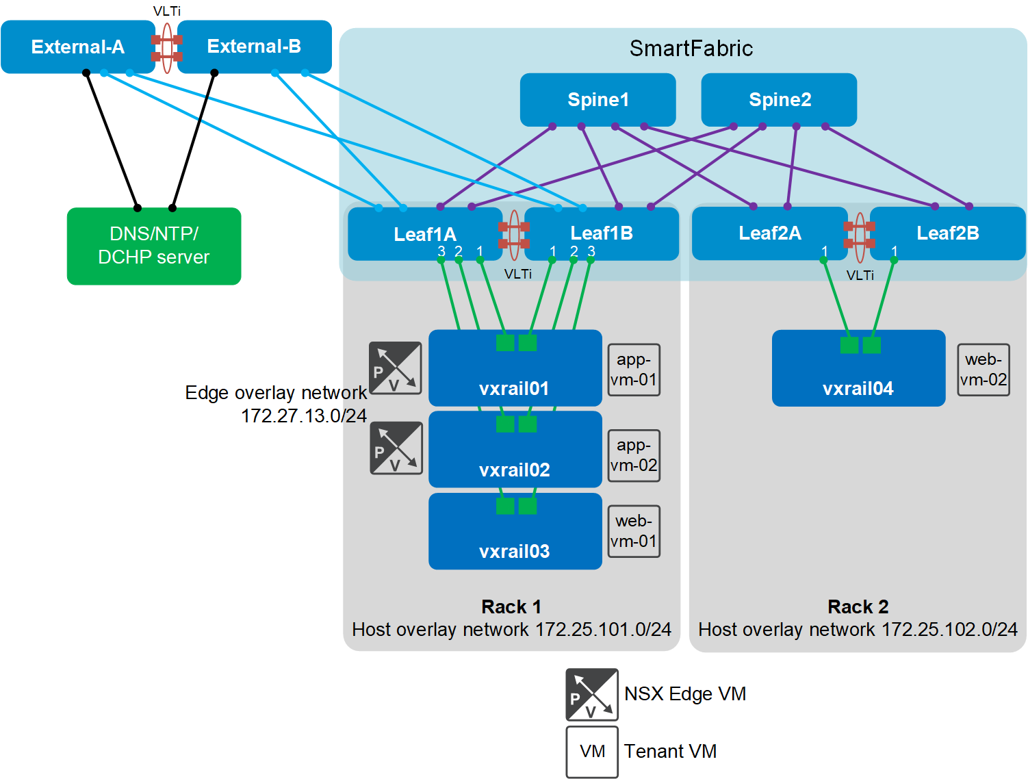
The sections that follow show example Traceflow reports for this deployment. The locations of VxRail nodes and tenant VMs are shown in the figure below. The NSX Edge cluster is in Rack 1. The host overlay and edge overlay network TEP addresses are also shown.
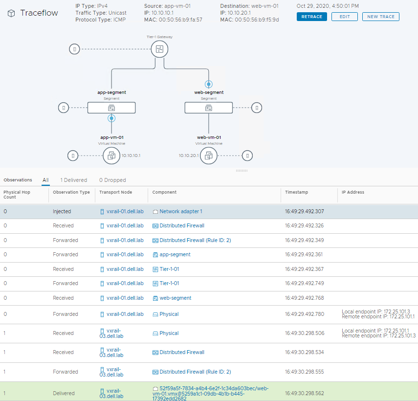
VMs in same rack on different segments
The following figure shows the Traceflow result from app-vm-01 and web-vm-01 in Rack 1. The Tier-1 gateway is used to route between segments. The IP Address column on the right shows the host overlay network TEP addresses.
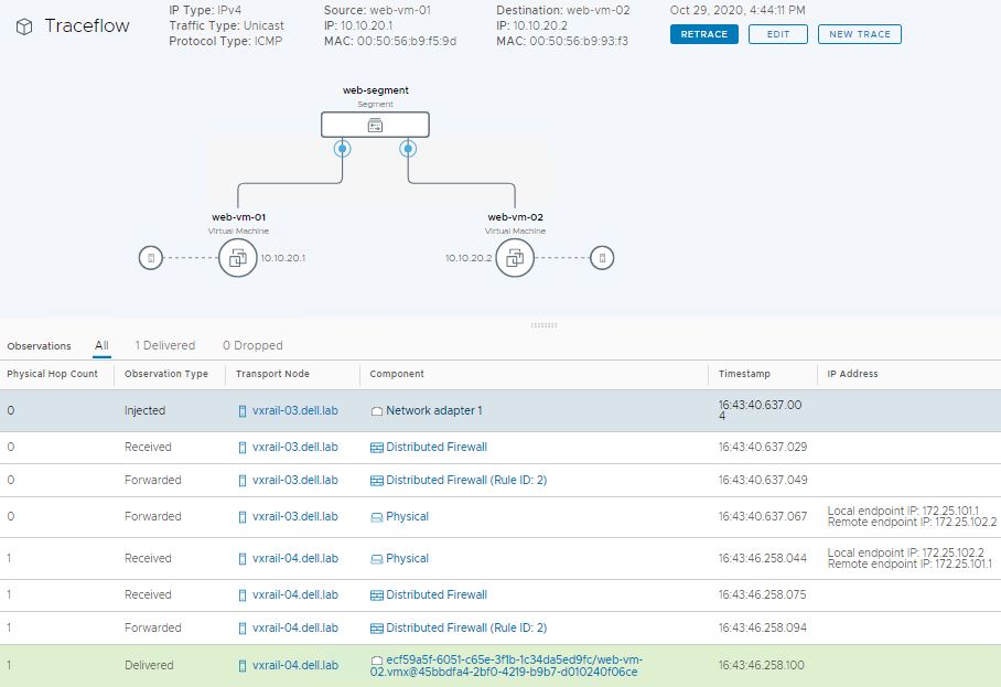
VMs in different racks on same segment
The following figure shows the Traceflow result from web-vm-01 in Rack 1 to web-vm-02 in Rack 2. The IP Address column on the right shows the host overlay network TEP addresses.
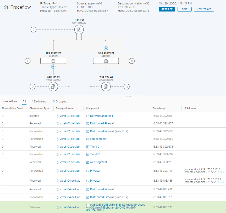
VMs in different racks on different segments
The following figure shows a Traceflow run between app-vm-01 in Rack 1 and web-vm-02 in Rack 2. The Tier-1 gateway is used to route between segments. The right column shows the host overlay network TEP addresses.
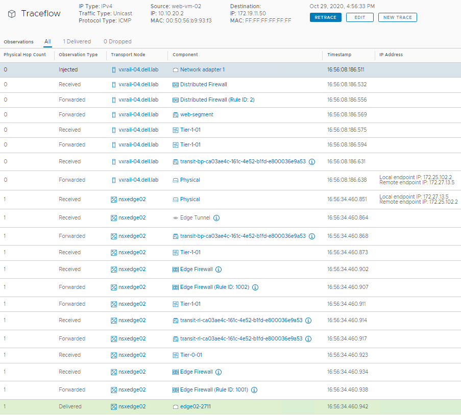
VM to DNS server on external network
The following figure shows a Traceflow run between web-vm-02 in Rack 2 and the DNS server on the external network. The Tier-1 gateway forwards to the Tier-0 gateway. The IP address column shows the host overlay network and edge overlay network TEP addresses. An NSX Edge is used as a transport node to reach the external network.