
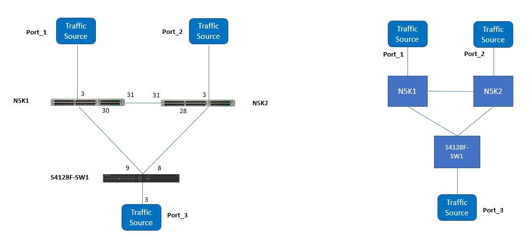
The Physical and logical reference network test-bed with spanning tree figure below shows the reference test-bed diagram that is used for the first set of tests. Tagged traffic was generated and transmitted from either ends of the network. Some test cases source traffic from Ports 1 and 2 to Port 3, and others sourced traffic from Port 3 to Ports 2 and 1. RPVST+ is the spanning tree mode that is enabled by default in Dell EMC SmartFabric OS10.
The following figure shows the reference test-bed diagram that is used for the second set of tests.
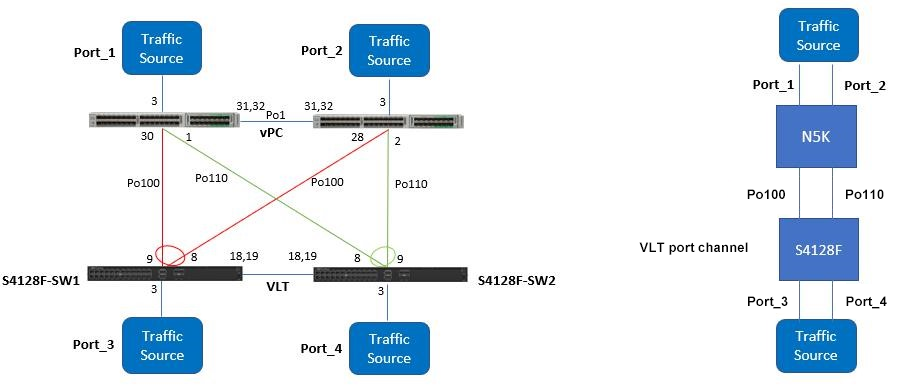
Dell EMC SmartFabric OS10 Virtual Link Trunking (VLT) aggregates two identical physical switches to form a single logical extended switch. This single logical entity ensures high availability and high resilience for all its connected access, core switches, and clients.
VLT provides a Layer 2 multipath which creates redundancy through increased bandwidth, enables multiple parallel paths between nodes, and load-balances traffic where alternative paths exist. A VLT interconnect (VLTi) synchronizes states between VLT peers. The Test setup with VLT and vPC image above shows the typical network layout with VLT.
The Cisco vPC, or Virtual Port Channel, allows links that are physically connected to two different Cisco Nexus® devices to appear as a single port channel to a third device. The third device can be a Cisco Nexus 2000 Series Fabric Extender, a switch, server, or any other networking device. A vPC provides Layer 2 multipathing, which allows you to create redundancy by increasing the bandwidth, enabling multiple parallel paths between nodes, and load-balancing traffic where alternative paths exist. The vPC domain includes both vPC peer devices, the vPC peer keepalive link, the vPC peer link, and all the port-channels in the vPC domain connected to the downstream device. You can have only one vPC domain ID on each device.
Notice that when vPC and VLT are configured, the logical network topology creates a simple pair of switches that is connected back-to-back using a quad member port channel link.
The quad member port channel link comes from the dual homed links from each switch (Cisco Nexus 5548UP and Dell EMC PowerSwitch S4128F-ON) where the Cisco single port channel links are identified in red and green from each switch, and the Dell EMC dual port channel links are identified with a circle icon. Once spanning tree protocol runs, the port-channel goes into the forwarding mode because to spanning tree, this is a single port-channel with four links, not two separate individual port channels where one must be blocked in order to avoid a loop in the network.
The following hardware and software is used in this exercise:
- Hardware
- Dell EMC PowerSwitch S4128F-ON (two)
- Cisco Nexus 5548UP (two)
- IXIA XM2 chassis with 4-10GE for the traffic source
- Cisco Catalyst 4900 series switch
- Module software
- Dell EMC SmartFabric OS10 (version 10.5.2.1)
- Cisco 5.1 (3) N2 (1)
The following formulae were used to calculate the frame loss and frame loss duration:
- Frame Loss = (Total Frames Sent – Total Frames Received) \ Total Frames Sent
- Frame Loss Duration = (Total Frames Sent – Total Frames Received) \ Frames Sent Rate