
Dell Virtual Link Trunking allows Layer 2 information to be shared across the two nodes. For this purpose, the same VLT domain-id should be configured on both VLT nodes. For rapid convergence and optimal service, the same VLT MAC address should be configured on both the nodes using the vlt-mac command (optional). In the absence of vlt-mac configuration, if the primary VLT node goes down, the VLT port-channel on the secondary node flaps, causing slight traffic disruption.
The primary node election's priority is based on the lower system mac-address of the switch; however, with the primary-priority command, the VLT node with the least configured priority takes over as the primary node. This election will not be preempted. If the primary node is reloaded, it is assigned the secondary role. The role change avoids disruptions in traffic flow due to the election process.
The election happens only during the initial configuration or when VLT is initially launched. The VLT role election has no significance for the data traffic flowing through the VLT domain. It is only for the control protocol exchange and handles potential split-control failure scenarios.
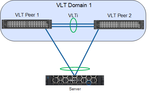
VLAN ID 4094 is assigned automatically and internally reserved as a control VLAN to exchange VLT-related information between the nodes. The IPv6 address that is automatically assigned within the reserved range is mapped for VLAN 4094 for reachability between the VLT nodes.
For the VLT interconnect (VLTi) link, once the discovery interfaces are configured on both nodes, port-channel 1000 is automatically configured, mapping the physical discovery interfaces. The ports should be configured as no switchport from the default Layer 2 mode while configuring the discovery interfaces.
Every thirty seconds, heartbeat messages are sent between the VLT nodes to check the liveliness of the peers and to handle the VLTi failure scenario. The heartbeat interval value is configurable and reaches the peer through the backup destination. Similarly, keep-alive messages (non-configurable) are sent through the VLTi port-channel.
For VLT port-channels, the user should explicitly assign the vlt-port-channel id to the configured port-channel on both of the nodes. This port-channel identifier should be the same for both of the nodes.
Important points to remember:
VLT port-channel interfaces must be switch ports.
Dell Technologies strongly recommends that the VLTi (VLT interconnect) be a static LAG and that you disable LACP on the VLTi.
If you include RSTP/PVST, and it must be configured before VLT is configured.
VLT Heartbeat is supported only on default VRFs.
If you enable IGMP snooping on the VLT peers, ensure the value of the
delay-restorecommand is not less than the query interval.Ensure that the spanning tree root bridge is at the Aggregation layer.
VLT interconnect over 1G ports is not supported.
Each VLT domain has a unique MAC address that you create.
In a VLT domain, the peer switches must run the same Dell Networking OS software version.
If you replace a VLT peer node, preconfigure the switch with the VLT system MAC address, unit-id, and other VLT parameters before connecting it to the existing VLT peer switch using the VLTi connection.
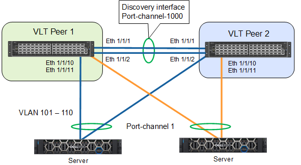
In this sample configuration, the 1/1/1 and 1/1/2 interfaces form the discovery interface/VLTi (Po-1000) on the VLT Peer1. Similarly, the 1/1/1 and 1/1/2 interfaces form the discovery interface on VLT Peer2. The VLT backup destination is mapped to the remote peer's management IP address. Port-channel 1 is configured on both VLT nodes as interface 1/1/10 and 1/1/11. VLAN 101-110 is mapped to port-channel 1.
The configurations for VLT-Peer1 and VLT-Peer2 are the same except for the back-up destination IP address. The sample configuration for VLT-Peer1 is as follows:
VLT-Peer1# configure terminal
VLT-Peer1(config)# interface ethernet 1/1/1
VLT-Peer1(conf-if-eth1/1/1)# no shutdown
VLT-Peer1(conf-if-eth1/1/1)# no switchport
VLT-Peer1(conf-if-eth1/1/1)# exit
VLT-Peer1(config)# interface ethernet 1/1/2
VLT-Peer1(conf-if-eth1/1/2)# no shutdown
VLT-Peer1(conf-if-eth1/1/2)# no switchport
VLT-Peer1(conf-if-eth1/1/2)#exit
VLT-Peer1(config)# vlt-domain 1
VLT-Peer1(conf-vlt-1)# primary-priority 1
VLT-Peer1(conf-vlt-1)# vlt-mac de:11:de:11:de:11
VLT-Peer1(conf-vlt-1)# discovery-interface ethernet 1/1/1
VLT-Peer1(conf-vlt-1)# discovery-interface ethernet 1/1/2
VLT-Peer1(conf-vlt-1)# backup destination 10.16.208.184
VLT-Peer1(config)# interface range vlan 101-110
VLT-Peer1(conf-range-vl-101-110)#exit
VLT-Peer1(config)# interface port-channel 1
VLT-Peer1(conf-if-po-1)# switchport mode trunk
VLT-Peer1(conf-if-po-1)# switchport trunk allowed vlan 101-110
 VLT-Peer1(conf-if-po-1)#end