
Configure L3 routed uplinks to the external network
Configure L3 routed uplinks to the external network
-
Uplinks to the existing network may be configured as L2, L3 routed, or L3 VLAN. This section covers L3 routed uplinks.
Note: If L2 uplinks were configured in the preceding section, skip this section and go to Configure a jump host port.
Note: L3 VLAN uplink configuration is beyond the scope of this guide.
Connections, port numbers, and networks used for external management are shown in Figure 26. The External Management VLAN is VLAN 1711 on the external switches and is VLAN 1811 on the SmartFabric switches.
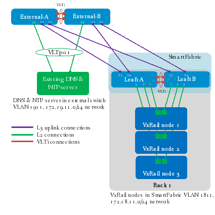
Figure 26. L3 routed uplinks to the external network
Point-to-point IP networks
The point-to-point links used in this deployment are labeled A-E in Figure 27.
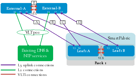
Figure 27. Point to Point connections
Each L3 uplink is a separate, point-to-point IP network. Table 6 details the links labeled in Figure 27. The IP addresses in the table are used in the switch configuration examples.
Table 6. L3 routed uplink IP addresses
Link label
Source switch
Source IP address
Destination switch
Destination IP address
Network
A
External-A
192.168.1.0
Leaf1A
192.168.1.1
192.168.1.0/31
B
External-A
192.168.1.2
Leaf1B
192.168.1.3
192.168.1.2/31
C
External-B
192.168.2.0
Leaf1A
192.168.2.1
192.168.2.0/31
D
External-B
192.168.2.2
Leaf1B
192.168.2.3
192.168.2.2/31
E
External-A
192.168.3.20
External-B
192.168.3.21
192.168.3.20/31
BGP Example
This section covers the L3 routed uplink configuration with BGP.
Note: If BGP is not used, go to the Static route example.
BGP ASNs and router IDs
Figure 28 shows the autonomous system numbers (ASNs) and router IDs used for the external switches and SFS leaf switches in this example. External switches share a common ASN, and all SFS leaf switches share a common ASN.
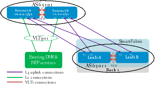
Figure 28. BGP ASNs and router IDs
Note: Using private ASNs in the data center is a best practice. Private, 2-byte ASNs range from 64512 through 65534.
In this example, ASN 65101 is used on both external switches. SFS leaf switches use ASN 65011 by default for all leafs in the fabric.
Note: If L3 uplinks are connected from SFS spine switches, the spine switches use ASN 65012 by default.
The IP addresses shown on the external network switches in Figure 28 are loopback addresses used as BGP router IDs. On the SmartFabric switches, BGP router IDs are automatically configured from the SFS default private subnet address block, 172.16.0.0/16.
Note: SFS default ASNs and IP address blocks may be changed by going to 5. Edit Default Fabric Settings in the SFS GUI.
Configure L3 routed uplinks with BGP in SFS
Table 7 shows the values entered in the SFS GUI to configure the L3 uplinks for this example. The steps below the table are run once for each uplink using the values in the table.
Table 7. L3 uplink configuration details with BGP
Field name
Leaf1A-to-External-A
Leaf1A-to-External-B
Leaf1B-to-External-A
Leaf1B-to-External-B
Uplink Type
L3 Routed
L3 Routed
L3 Routed
L3 Routed
Uplink Name
Leaf1A-to-External-A
Leaf1A-to-External-B
Leaf1B-to-External-A
Leaf1B-to-External-B
Switch Group
Leaf
Leaf
Leaf
Leaf
Rack
Rack 1
Rack 1
Rack 1
Rack 1
Leaf Switch
Leaf1A
Leaf1A
Leaf1B
Leaf1B
Interface
Ethernet 1/1/53
Ethernet 1/1/54
Ethernet 1/1/53
Ethernet 1/1/54
Network Name
Leaf1A-to-ExtA
Leaf1A-to-ExtB
Leaf1B-to-ExtA
Leaf1B-to-ExtB
IPv4 Address
192.168.1.1
192.168.2.1
192.168.1.3
192.168.2.3
Prefix Length
31
31
31
31
Routing Protocol
eBGP
eBGP
eBGP
eBGP
Profile Name
eBGP-Leaf1A-to-ExtA
eBGP-Leaf1A-to-ExtB
eBGP-Leaf1B-to-ExtA
eBGP-Leaf1B-to-ExtB
Peer IPv4 Address
192.168.1.0
192.168.2.0
192.168.1.2
192.168.2.2
Remote ASN
65101
65101
65101
65101
Note: Any ports available on the leaf switches may be used as uplinks, provided they are compatible with the corresponding ports on the external switches. If leaf switch uplink ports will not use their native speeds, the interfaces must be first broken out to the correct speed before the uplinks are created. This is done using the 1. Breakout Switch Ports option on the SFS GUI home page. A breakout example is shown in the Change the port-group speed in the SFS GUI section of this guide.
To configure L3 routed uplinks with BGP, do the following using the data from Table 7:
- In the SFS GUI, select 2. Create Uplink for External Network Connectivity.

Figure 29. SFS GUI Home Page
- On the Uplink Details page:
- Set Uplink Connectivity to Layer 3.
- Leave Network Type set to L3 Routed.
- Enter a unique Name and, optionally, a Description.
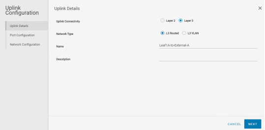
Figure 30. Uplink Details
- Click NEXT.
- On the Port Configuration page:
- Leave Switch Group set to Leaf.
- Next to Rack, select the rack that contains the switches with the uplinks. In this example, Rack 1 is selected.
- Next to Leaf Switch, select the first leaf, Leaf1A in this example.
- Next to Configured Interface, select the first interface. In this example, 100 GbE interface 1/1/53 is selected.
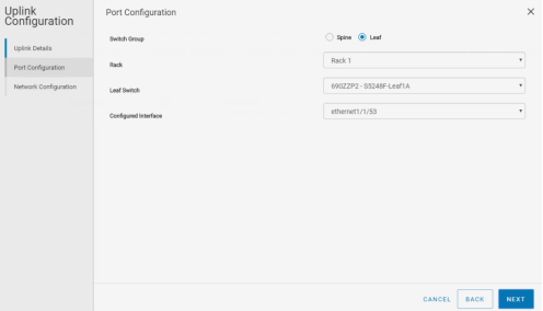
Figure 31. Port Configuration
- Click NEXT.
- On the Network Configuration page:
- Enter a unique Name and, optionally, a Description.
- Enter the Interface IP Address and Prefix length.
- Select the Routing Protocol, eBGP.
- Enter a unique Profile Name.
- Enter the Peer Interface IP Address and Remote ASN.
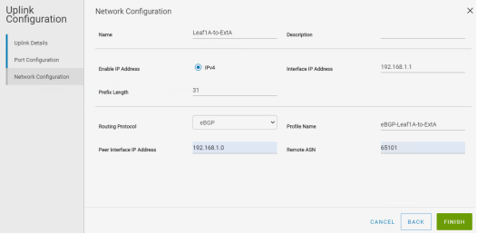
Figure 32. Network Configuration page with BGP
- Click FINISH.
Repeat the steps in this section for the remaining three uplinks using the data from Table 7.
After uplink configuration, the SFS GUI Home page appears, as shown in Figure 33.
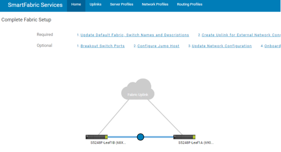
Figure 33. SFS Home page after uplinks configured
Individual uplinks created are visible on the Uplinks tab of the SFS GUI, as shown in Figure 34.
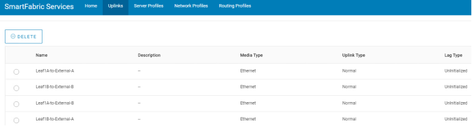
Figure 34. SFS L3 uplinks created
Static route example
This section shows L3 routed uplink configuration with a static route.
Note: If BGP is used instead of a static route, continue to Configure external switches for L3 connections.
Note: Currently, only one static route per L3 uplink is allowed. If multiple routes are needed, use a default route, 0.0.0.0/0, as the destination network, or add additional uplinks for specific networks. Support for multiple static routes per L3 uplink is planned for a future release.
Configure L3 uplinks with a static route in SFS
Table 8 shows the values entered in the SFS GUI to configure the L3 uplinks for this example. The steps below the table are run once for each uplink using the values from the table.
Table 8. L3 uplink configuration details with a static route
Field name
Leaf1A-to-External-A
Leaf1A-to-External-B
Leaf1B-to-External-A
Leaf1B-to-External-B
Uplink Type
L3 Routed
L3 Routed
L3 Routed
L3 Routed
Uplink Name
Leaf1A-to-External-A
Leaf1A-to-External-B
Leaf1B-to- External-A
Leaf1B-to- External-B
Switch Group
Leaf
Leaf
Leaf
Leaf
Rack
Rack 1
Rack 1
Rack 1
Rack 1
Leaf Switch
Leaf1A
Leaf1A
Leaf1B
Leaf1B
Interface
Ethernet 1/1/53
Ethernet 1/1/54
Ethernet 1/1/53
Ethernet 1/1/54
Network Name
Leaf1A-to-ExtA
Leaf1A-to-ExtB
Leaf1B-to-ExtA
Leaf1B-to-ExtB
IPv4 Address
192.168.1.1
192.168.2.1
192.168.1.3
192.168.2.3
Prefix Length
31
31
31
31
Routing Protocol
Static Route
Static Route
Static Route
Static Route
Policy Name
Leaf1A-to-ExtA
Leaf1A-to-ExtB
Leaf1B-to-ExtA
Leaf1B-to-ExtB
Network Address
172.19.11.0
172.19.11.0
172.19.11.0
172.19.11.0
Prefix Length
24
24
24
24
Next Hop IP Address
192.168.1.0
192.168.2.0
192.168.1.2
192.168.2.2
Note: Any ports available on the leaf switches may be used as uplinks, provided they are compatible with the corresponding ports on the external switches. If leaf switch uplink ports will not use their native speeds, the interfaces must be first broken out to the correct speed before the uplinks are created. This is done using the 1. Breakout Switch Ports option on the SFS GUI home page. A breakout example is shown in the Change the port-group speed in the SFS GUI section of this guide.
To configure L3 routed uplinks with a static route, do the following:
- In the SFS GUI, select 2. Create Uplink for External Network Connectivity.
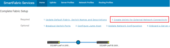
Figure 35. SFS GUI Home Page
- On the Uplink Details page:
- Set Uplink Connectivity to Layer 3.
- Leave Network Type set to L3 Routed.
- Enter a unique Name and, optionally, a Description.
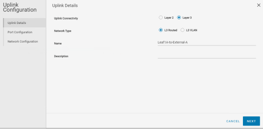
Figure 36. Uplink Details
- Click NEXT.
- On the Port Configuration page:
- Leave Switch Group set to Leaf.
- Next to Racks, select the rack that contains the uplink switches. In this example, Rack 1 is selected.
- Next to Leaf Switches, select the first leaf, Leaf1A in this example.
- Next to Configured Interfaces, select the first interface. In this example, 100 GbE interface 1/1/53 is selected.
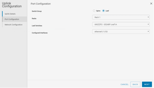
Figure 37. Port Configuration
- Click NEXT.
- On the Network Configuration page:
- Enter a unique Name and, optionally, a Description.
- Enter the Interface IP Address and Prefix length.
- Leave Routing Protocol set to Static Route.
- Enter a unique Policy Name.
- Enter the destination Network Address and Prefix Length. This is the external management network, 172.19.11.0/24, in this example.
- Enter the Next Hop IP Address. This is the IP address of the connected interface on the external switch.
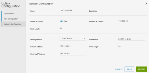
Figure 38. Network Configuration page with a static route
- Click FINISH.
Repeat the steps in this section for the remaining three uplinks using the data from Table 8.
After uplink configuration, the SFS GUI Home page appears as shown in Figure 39.
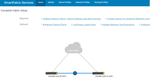
Figure 39. SFS Home page after uplink configuration
Individual uplinks created are visible on the Uplinks tab of the SFS GUI, as shown in Figure 40.
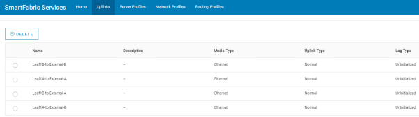
Figure 40. SFS L3 uplinks created
Configure external switches for L3 connections
This section shows example configurations for both external switches for L3 routed connections to the SmartFabric.
Note: The external switches used in this example are Dell EMC PowerSwitch systems. If the external switches are Cisco Nexus, see Appendix C.
Note: This is only an example. Modify your external switch configuration as needed for your network.
General settings
Configure the hostname, OOB management IP address, and management route.
External-A
External-B
configure terminal
hostname External-A
interface mgmt1/1/1
no ip address
ip address 100.67.127.37/24
no shutdown
management route 100.67.0.0.0/16 100.67.127.254
configure terminal
hostname External-B
interface mgmt1/1/1
no ip address
ip address 100.67.127.36/24
no shutdown
management route 100.67.0.0/16 100.67.127.254
Configure VLANs
VLAN 1911 represents a preexisting management VLAN on the external network. DNS and NTP services are located on this VLAN. Assign a unique IP address to the VLAN on each switch.
Configure VRRP to provide gateway redundancy. Set the VRRP priority. The switch with the highest priority value becomes the master VRRP router. Assign the same virtual address to both switches.
External-A
External-B
interface vlan1911
no shutdown
ip address 172.19.11.252/24
vrrp-group 19
priority 150
virtual-address 172.19.11.254
interface vlan1911
no shutdown
ip address 172.19.11.253/24
vrrp-group 19
priority 100
virtual-address 172.19.11.254
Configure interfaces
Configure the interfaces for connections to the SFS switches. Ports 1/1/21 and 1/1/22 are configured as L3 interfaces. The IP addresses used are from Table 6. Optionally, allow the forwarding of jumbo frames with the MTU 9216 command. As a best practice, flow control settings remain at their factory defaults as shown.
In this example, VLT port channel 1 connects to the DNS/NTP server. It is on VLAN 1911, which represents the preexisting management VLAN, and the port channel is configured as a spanning tree edge port.
Interface 1/1/33 on each external switch is configured in VLT port channel 1 for connections to the DNS/NTP server. Port-channel 1 is set as an LACP port channel with the channel-group 1 mode active command.
External-A
External-B
interface ethernet1/1/21
description Leaf1A
no shutdown
no switchport
mtu 9216
ip address 192.168.1.0/31
flowcontrol receive on
flowcontrol transmit off
interface ethernet1/1/22
description Leaf1B
no shutdown
no switchport
mtu 9216
ip address 192.168.1.2/31
flowcontrol receive on
flowcontrol transmit off
interface port-channel1
description "To DNS/NTP"
no shutdown
switchport access vlan 1911
vlt-port-channel 1
spanning-tree port type edge
interface ethernet1/1/33
description "To DNS/NTP"
no switchport
channel-group 1 mode active
no shutdown
flowcontrol receive on
flowcontrol transmit off
interface ethernet1/1/21
description Leaf1A
no shutdown
no switchport
mtu 9216
ip address 192.168.2.0/31
flowcontrol receive on
flowcontrol transmit off
interface ethernet1/1/22
description Leaf1B
no shutdown
no switchport
mtu 9216
ip address 192.168.2.2/31
flowcontrol receive on
flowcontrol transmit off
interface port-channel1
description "To DNS/NTP"
no shutdown
switchport access vlan 1911
vlt-port-channel 1
spanning-tree port type edge
interface ethernet1/1/33
description "To DNS/NTP"
no switchport
channel-group 1 mode active
no shutdown
flowcontrol receive on
flowcontrol transmit off
Configure VLT
This example uses interfaces 1/1/29 and 1/1/31 for the VLTi. Remove each interface from L2 mode with the no switchport command. As a best practice, flow control settings remain at their factory defaults, as shown.
Create the VLT domain. The backup destination is the OOB management IP address of the VLT peer switch. Configure the interfaces used as the VLTi with the discovery-interface command.
As a best practice, use the vlt-mac command to manually configure the same VLT MAC address on both the VLT peer switches. This improves VLT convergence time when a switch is reloaded.
Caution: Be sure the VLT MAC address is the same on both switches to avoid any unpredictable behavior.
If you do not configure a VLT MAC address, the MAC address of the primary peer is used as the VLT MAC address on both switches.
Note: For more information about VLT, see the Dell EMC SmartFabric OS10 User Guide on the Dell EMC Networking OS10 Info Hub.
External-A
External-B
interface range ethernet1/1/29,1/1/31
description VLTi
no switchport
no shutdown
flowcontrol receive on
flowcontrol transmit off
vlt-domain 255
backup destination 100.67.127.36
discovery-interface ethernet1/1/29,1/1/31
vlt-mac 00:00:01:02:03:20
interface range ethernet1/1/29,1/1/31
description VLTi
no shutdown
no switchport
flowcontrol receive on
flowcontrol transmit off
vlt-domain 255
backup destination 100.67.127.37
discovery-interface ethernet1/1/29,1/1/31
vlt-mac 00:00:01:02:03:20
Configure BGP
Note: If BGP is not used, go to the Configure static routes section.
Configure a loopback interface to use for the BGP router ID.
Configure the BGP ASN with the router bgp command. The external switches share the same ASN. Use the address that was set for interface loopback0 as the router ID.
Use the address-family ipv4 unicast and redistribute connected commands to redistribute IPv4 routes from physically connected interfaces.
Configure the neighbor IP addresses and ASNs.
VLAN 4000 is used for the iBGP connection between the external switches. VLAN4000 IP addresses are configured per Table 6.
When the configuration is complete, exit configuration mode and save the configuration with the end and write memory commands.
External-A
External-B
interface loopback0
description router_ID
no shutdown
ip address 10.0.2.1/32
router bgp 65101
router-id 10.0.2.1
address-family ipv4 unicast
redistribute connected
neighbor 192.168.1.1
remote-as 65011
no shutdown
neighbor 192.168.1.3
remote-as 65011
no shutdown
neighbor 192.168.3.21
remote-as 65101
no shutdown
interface vlan4000
description iBGP
no shutdown
ip address 192.168.3.20/31
end
write memory
interface loopback0
description router_ID
no shutdown
ip address 10.0.2.2/32
router bgp 65101
router-id 10.0.2.2
address-family ipv4 unicast
redistribute connected
neighbor 192.168.2.1
remote-as 65011
no shutdown
neighbor 192.168.2.3
remote-as 65011
no shutdown
neighbor 192.168.3.20
remote-as 65101
no shutdown
interface vlan4000
description iBGP
no shutdown
ip address 192.168.3.21/31
end
write memory
Configure static routes
Note: If BGP is used, skip this section and go to Validate BGP example.
Configure two routes to the external management network. This is 172.18.11.0/24, one to the connected IP address of Leaf1A, and one to Leaf1B.
When the configuration is complete, exit configuration mode and save the configuration with the end and write memory commands.
External-A
External-B
ip route 172.18.11.0/24 192.168.1.1
ip route 172.18.11.0/24 192.168.1.3
end
write memory
ip route 172.18.11.0/24 192.168.2.1
ip route 172.18.11.0/24 192.168.2.3
end
write memory
Validate BGP example
Note: This section shows validation commands for the BGP example. If static routes are used, skip this section and go to Validate static route example.
Now that the uplink interfaces are configured on the external switches and on the SFS leaf switches, connectivity can be verified using the switch CLI.
Show command output on External-A (BGP example)
Note: The command output shown in the following commands is for the External-A switch. The output for External-B is similar.
Run the show ip bgp summary command to verify that BGP is up for each neighbor. When BGP is up, uptime is shown in the Up/Down column. The neighbors for External-A shown in the output below are Leaf1A, Leaf1B, and External-B.
External-A# show ip bgp summary
BGP router identifier 10.0.2.1 local AS number 65101
Neighbor AS MsgRcvd MsgSent Up/Down State/Pfx
192.168.1.1 65011 1327 1316 19:09:00 4
192.168.1.3 65011 1325 1324 19:09:00 4
192.168.3.21 65101 1319 1315 19:01:18 5
Run the show ip interface brief command to verify connected interfaces are up, and IP addresses are configured correctly. VLAN 1911 is the external management VLAN that contains the DNS/NTP server. VLAN 4094 and port channel 1000 are automatically configured for the VLTi.
Note: Unused interfaces have been removed from the output for brevity.
External-A# show ip interface brief
Interface Name IP-Address OK Method Status Protocol
================================================================================
Ethernet 1/1/21 192.168.1.0/31 YES manual up up
Ethernet 1/1/22 192.168.1.2/31 YES manual up up
Ethernet 1/1/29 unassigned YES unset up up
Ethernet 1/1/31 unassigned YES unset up up
Ethernet 1/1/33 unassigned YES unset up up
Management 1/1/1 100.67.127.37/24 YES manual up up
Vlan 1 unassigned YES unset up up
Vlan 1911 172.19.11.252/24 YES manual up up
Vlan 4000 192.168.3.20/31 YES manual up up
Vlan 4094 unassigned YES unset up up
Port-channel 1 unassigned YES unset up up
Port-channel 1000 unassigned YES unset up up
Loopback 0 10.0.2.1/32 YES manual up up
The show ip route command output for the External-A switch appears as shown. No BGP routes from the SFS fabric are learned at this stage of deployment. Interfaces 1/1/21 and 1/1/22 are connected to the SFS leaf switches.
External-A# show ip route
Codes: C - connected
S - static
B - BGP, IN - internal BGP, EX - external BGP
O - OSPF, IA - OSPF inter area, N1 - OSPF NSSA external type 1,
N2 - OSPF NSSA external type 2, E1 - OSPF external type 1,
E2 - OSPF external type 2, * - candidate default,
+ - summary route, > - non-active route
Gateway of last resort is not set
Destination Gateway Dist Last Change
----------------------------------------------------------------------------------
C 10.0.2.1/32 via 10.0.2.1 loopback0 0/0 00:39:19
B IN 10.0.2.2/32 via 192.168.3.21 200/0 00:31:38
C 172.19.11.0/24 via 172.19.11.252 vlan1911 0/0 00:44:00
C 192.168.1.0/31 via 192.168.1.0 ethernet1/1/21 0/0 01:44:44
C 192.168.1.2/31 via 192.168.1.2 ethernet1/1/22 0/0 01:40:50
B IN 192.168.2.0/31 via 192.168.3.21 200/0 00:31:38
B IN 192.168.2.2/31 via 192.168.3.21 200/0 00:31:38
C 192.168.3.20/31 via 192.168.3.20 vlan4000 0/0 00:31:51
Show command output on Leaf1A (BGP example)
Note: The command output shown in the following commands is for Leaf1A. The output for Leaf1B is similar.
Run the show ip bgp summary command to verify that BGP is up for each neighbor. When BGP is up, uptime is shown in the Up/Down column. The neighbors for Leaf1A shown in the output below are Leaf1B, External-A, and External-B.
S5248F-Leaf1A# show ip bgp summary
BGP router identifier 172.16.128.0 local AS number 65011
Neighbor AS MsgRcvd MsgSent Up/Down State/Pfx
172.16.0.0 65011 13 16 00:06:59 8
192.168.1.0 65101 12 14 00:07:30 8
192.168.2.0 65101 8 9 00:04:14 8
Run the show ip interface brief command to verify connected interfaces are up, and IP addresses are configured correctly.
In the output below, interfaces 1/1/1-1/1/3 are connected to the VxRail nodes, 1/1/49-1/1/52 are the VLTi, and 1/1/53-1/1/54 are the uplinks to the external switches. SFS uses VLAN 4090, Loopback 1, and Loopback 2 internally. VLAN 4094 and port channel 1000 are automatically configured for the VLTi.
Note: Unused interfaces have been removed from the output for brevity.
S5248F-Leaf1A# show ip interface brief
Interface Name IP-Address OK Method Status Protocol
================================================================================
Ethernet 1/1/1 unassigned YES unset up up
Ethernet 1/1/2 unassigned YES unset up up
Ethernet 1/1/3 unassigned YES unset up up
Ethernet 1/1/49 unassigned YES unset up up
Ethernet 1/1/50 unassigned YES unset up up
Ethernet 1/1/51 unassigned YES unset up up
Ethernet 1/1/52 unassigned YES unset up up
Ethernet 1/1/53 192.168.1.1/31 YES manual up up
Ethernet 1/1/54 192.168.2.1/31 YES manual up up
Management 1/1/1 100.67.127.28/24 YES manual up up
Vlan 4000 unassigned YES unset up up
Vlan 4090 172.16.0.1/31 YES manual up up
Vlan 4094 unassigned YES unset up up
Port-channel 1000 unassigned YES unset up up
Loopback 1 172.16.128.0/32 YES manual up up
Loopback 2 172.30.0.0/32 YES manual up up
Virtual-network 3939 unassigned YES unset up up
Run the show ip route command to verify routes to the external management VLAN, 172.19.11.0/24, have been learned using BGP from the external switches. In this example, two routes to 172.19.11.0/24 are learned, one using each external switch.
S5248F-Leaf1A# show ip route
Codes: C - connected
S - static
B - BGP, IN - internal BGP, EX - external BGP
O - OSPF, IA - OSPF inter area, N1 - OSPF NSSA external type 1,
N2 - OSPF NSSA external type 2, E1 - OSPF external type 1,
E2 - OSPF external type 2, * - candidate default,
+ - summary route, > - non-active route
Gateway of last resort is not set
Destination Gateway Dist Last Change
----------------------------------------------------------------------------------
B EX 10.0.2.1/32 via 192.168.1.0 20/0 00:43:16
via 192.168.2.0
B EX 10.0.2.2/32 via 192.168.1.0 20/0 00:43:16
via 192.168.2.0
C 172.16.0.0/31 via 172.16.0.1 vlan4090 0/0 02:19:46
C 172.16.128.0/32 via 172.16.128.0 loopback1 0/0 02:20:07
B IN 172.16.128.1/32 via 172.16.0.0 200/0 02:19:44
B EX 172.19.11.0/24 via 192.168.1.0 20/0 00:43:32
via 192.168.2.0
C 172.30.0.0/32 via 172.30.0.0 loopback2 0/0 02:20:07
C 192.168.1.0/31 via 192.168.1.1 ethernet1/1/53 0/0 01:12:49
B IN 192.168.1.2/31 via 172.16.0.0 200/0 01:09:12
C 192.168.2.0/31 via 192.168.2.1 ethernet1/1/54 0/0 01:10:18
B IN 192.168.2.2/31 via 172.16.0.0 200/0 01:07:51
B EX 192.168.3.20/31 via 192.168.1.0 20/0 00:43:21
via 192.168.2.0
Validate static route example
Note: This section shows validation commands for the static route example. If BGP was used, skip this section and go to Configure a jump host port.
Once the uplink interfaces have been configured on the external switches and in the SFS GUI, connectivity can be verified using the switch CLI.
Show command output on External-A (static route example)
Note: The command output shown in the following commands is for the External-A switch. The output for External-B is similar.
Run the show ip interface brief command to verify connected interfaces are up, and IP addresses are configured correctly. In the output below, interface 1/1/33 and port channel 1 connect to the DNS/NTP server. 1/1/21-1/1/22 are the links to the SFS leaf switches, and 1/1/29 and 1/1/31 are the VLTi links. VLAN 4094 and port channel 1000 are automatically configured for the VLTi.
Note: Unused interfaces have been removed from the output for brevity.
External-A# show ip interface brief
Interface Name IP-Address OK Method Status Protocol
================================================================================
Ethernet 1/1/21 192.168.1.0/31 YES manual up up
Ethernet 1/1/22 192.168.1.2/31 YES manual up up
Ethernet 1/1/29 unassigned YES unset up up
Ethernet 1/1/31 unassigned YES unset up up
Ethernet 1/1/33 unassigned YES unset up up
Management 1/1/1 100.67.127.37/24 YES manual up up
Vlan 1 unassigned YES unset up up
Vlan 1911 172.19.11.252/24 YES manual up up
Vlan 4094 unassigned YES unset up up
Port-channel 1 unassigned YES unset up up
Port-channel 1000 unassigned YES unset up up
Run the show ip route command to verify static routes to the external management VLAN, 172.18.11.0/24, are properly configured.
External-A# show ip route
Codes: C - connected
S - static
B - BGP, IN - internal BGP, EX - external BGP
O - OSPF, IA - OSPF inter area, N1 - OSPF NSSA external type 1,
N2 - OSPF NSSA external type 2, E1 - OSPF external type 1,
E2 - OSPF external type 2, * - candidate default,
+ - summary route, > - non-active route
Gateway of last resort is not set
Destination Gateway Dist Last Change
----------------------------------------------------------------------------------
S 172.18.11.0/24 via 192.168.1.1 ethernet1/1/21 1/0 3 days 23:35:18
via 192.168.1.3 ethernet1/1/22
C 172.19.11.0/24 via 172.19.11.252 vlan1911 0/0 3 days 23:26:55
C 192.168.1.0/31 via 192.168.1.0 ethernet1/1/21 0/0 21:58:31
C 192.168.1.2/31 via 192.168.1.2 ethernet1/1/22 0/0 21:58:33
Show command output on Leaf1A (static route example)
Note: The command output shown in the following commands is for Leaf1A. The output for Leaf1B is similar.
Run the show ip interface brief command to verify connected interfaces are up, and IP addresses are configured correctly.
In the output below, interfaces 1/1/1-1/1/3 are connected to the VxRail nodes, 1/1/49-1/1/52 are the VLTi links, and 1/1/53-1/1/54 are the uplinks to the external switches.
Note: Unused interfaces have been removed from the output for brevity.
S5248F-Leaf1A# show ip interface brief
Ethernet 1/1/1 unassigned YES unset up up
Ethernet 1/1/2 unassigned YES unset up up
Ethernet 1/1/3 unassigned YES unset up up
Ethernet 1/1/49 unassigned YES unset up up
Ethernet 1/1/50 unassigned YES unset up up
Ethernet 1/1/51 unassigned YES unset up up
Ethernet 1/1/52 unassigned YES unset up up
Ethernet 1/1/53 192.168.1.1/31 YES manual up up
Ethernet 1/1/54 192.168.2.1/31 YES manual up up
Management 1/1/1 100.67.127.28/24 YES manual up up
Vlan 4000 unassigned YES unset up up
Vlan 4090 172.16.0.1/31 YES manual up up
Vlan 4094 unassigned YES unset up up
Port-channel 1000 unassigned YES unset up up
Loopback 1 172.16.128.0/32 YES manual up up
Loopback 2 172.30.0.0/32 YES manual up up
Virtual-network 3939 unassigned YES unset up up
Run the show ip route command to verify static routes to the external management VLAN, 172.19.11.0/24, are correctly configured.
Note: Since BGP is used by SFS to exchange routes within the fabric, some BGP routes appear in the output.
S5248F-Leaf1A# show ip route
Codes: C - connected
S - static
B - BGP, IN - internal BGP, EX - external BGP
O - OSPF, IA - OSPF inter area, N1 - OSPF NSSA external type 1,
N2 - OSPF NSSA external type 2, E1 - OSPF external type 1,
E2 - OSPF external type 2, * - candidate default,
+ - summary route, > - non-active route
Gateway of last resort is not set
Destination Gateway Dist Last Change
----------------------------------------------------------------------------------
C 172.16.0.0/31 via 172.16.0.1 vlan4090 0/0 02:09:34
C 172.16.0.0/31 via 172.16.0.1 vlan4090 0/0 00:40:43
B IN 172.16.128.0/32 via 172.16.0.0 200/0 00:40:42
C 172.16.128.1/32 via 172.16.128.1 loopback1 0/0 00:40:50
S 172.19.11.0/24 via 192.168.1.0 ethernet1/1/53 1/0 00:37:51
via 192.168.2.0 ethernet1/1/54
C 172.30.0.0/32 via 172.30.0.0 loopback2 0/0 00:40:50
C 192.168.1.0/31 via 192.168.1.1 ethernet1/1/53 0/0 00:37:56
B IN 192.168.1.2/31 via 172.16.0.0 200/0 00:35:52
C 192.168.2.0/31 via 192.168.2.1 ethernet1/1/54 0/0 00:36:57
B IN 192.168.2.2/31 via 172.16.0.0 200/0 00:34:51