
Configure external Nexus switches for L3 routed connections
Configure external Nexus switches for L3 routed connections
-
SmartFabric uplinks may be connected to external Cisco Nexus switches. This appendix includes a Cisco Nexus 9000 switch configuration example for L3 routed connections to SmartFabric leaf switches.
Note: L3 routed uplinks on the SmartFabric leaf switches are configured per the Configure L3 routed uplinks with BGP in SFS section of this guide.
Connections, port numbers, and networks used for external management in this example are shown in Figure 125. The External Management VLAN is VLAN 1911 on the external Nexus switches, and is VLAN 1811 on the SmartFabric switches.
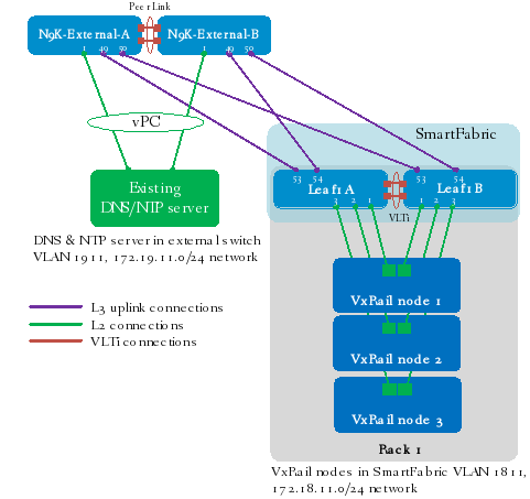
Figure 125. L3 routed uplinks from SmartFabric to external Nexus switches
In this example, an existing DNS/NTP server connects to the Nexus switches using a vPC in VLAN 1911.
Note: DNS and NTP servers do not have to connect in the manner shown if they are reachable on the network.
Point-to-point IP networks
The L3 point-to-point links used in this example are labeled A-D in Figure 126.
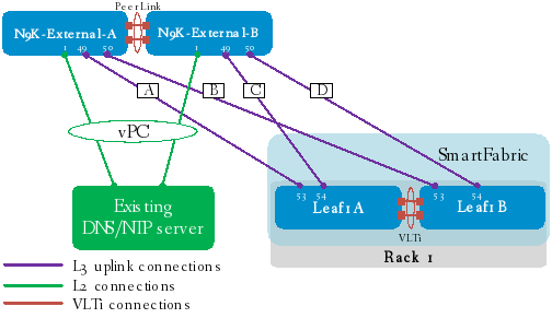
Figure 126. Point to Point connections
Each L3 uplink is a separate, point-to-point IP network. Table 19 details the links labeled in Figure 126. The IP addresses in the table are used in the switch configuration examples.
Table 19. L3 routed uplink IP addresses
Link label
Source switch
Source IP address
Destination switch
Destination IP address
Network
A
N9K-External-A
192.168.1.0
Leaf1A
192.168.1.1
192.168.1.0/31
B
N9K-External-A
192.168.1.2
Leaf1B
192.168.1.3
192.168.1.2/31
C
N9K-External-B
192.168.2.0
Leaf1A
192.168.2.1
192.168.2.0/31
D
N9K-External-B
192.168.2.2
Leaf1B
192.168.2.3
192.168.2.2/31
BGP ASNs and router IDs
Figure 127 shows the ASNs and router IDs used for the external Nexus switches and SFS leaf switches in this example. External switches share a common ASN, and all SFS leaf switches share a common ASN.
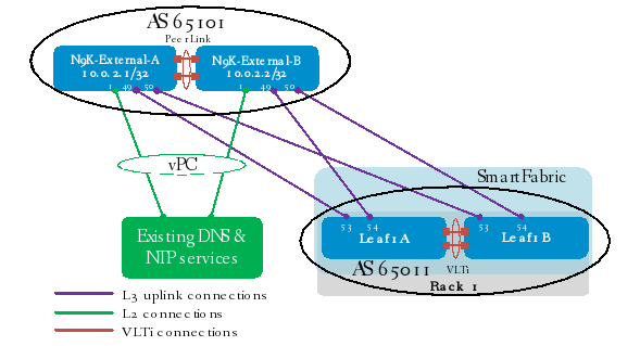
Figure 127. BGP ASNs and router IDs
In this example, ASN 65101 is used on both Nexus external switches. SFS leaf switches use ASN 65011 by default for all leafs in the fabric.
Note: If L3 uplinks are connected from SFS spine switches, the spine switches use ASN 65012 by default.
The IP addresses shown on the external network switches in Figure 127 are loopback addresses used as BGP router IDs. On the SmartFabric switches, BGP router IDs are automatically configured from the SFS default private subnet address block, 172.16.0.0/16.
Note: SFS default ASNs and IP address blocks may be changed by going to 5. Edit Default Fabric Settings in the SFS GUI.
Note: All of the Nexus switch configuration commands used to validate this topology are shown in the sections that follow. The Nexus switches were reset to their default configuration settings using the write erase command before running the configuration commands below. This is only an example. Modify your external switch configuration as needed for your environment.
General settings
Enable the following features: interface-vlan, lacp, vrrp, vpc, bgp, lldp. Configure the hostname, OOB management IP address on VRF management, and the VRF management route as shown.
N9K-External-A
N9K-External-B
configure terminal
feature interface-vlan
feature lacp
feature vrrp
feature vpc
feature bgp
feature lldp
hostname N9K-External-A
interface mgmt 0
ip address 100.67.127.30/24
vrf member management
no shutdown
vrf context management
ip route 100.67.0.0/16 100.67.127.254
configure terminal
feature interface-vlan
feature lacp
feature vrrp
feature vpc
feature bgp
feature lldp
hostname N9K-External-B
interface mgmt 0
ip address 100.67.127.29/24
vrf member management
no shutdown
vrf context management
ip route 100.67.0.0/16 100.67.127.254
Configure the External Management VLAN
VLAN 1911 represents a preexisting management VLAN on the external network. DNS and NTP services are located on this VLAN. Optionally, enable jumbo frames with the mtu 9216 command. Assign a unique IP address to the VLAN on each switch.
Configure VRRP to provide gateway redundancy and assign the same virtual address to both switches.
N9K-External-A
N9K-External-B
vlan 1911
name ExtMgmt
no shutdown
interface Vlan1911
description ExtMgmt
no shutdown
mtu 9216
ip address 172.19.11.252/24
vrrp 11
address 172.19.11.254
no shutdown
vlan 1911
name ExtMgmt
no shutdown
interface Vlan1911
description ExtMgmt
no shutdown
mtu 9216
ip address 172.19.11.253/24
vrrp 11
address 172.19.11.254
no shutdown
Configure the vPC domain and peer link
Create the vPC domain. The peer-keepalive destination is the OOB management IP address of the vPC peer switch.
Configure a port channel to use as the vPC peer link. Put the port channel in trunk mode and allow the default and External Management VLANs, 1 and 1911 respectively.
Configure the interfaces to use in the vPC peer link. Put the interfaces in trunk mode and allow the default and External Management VLANs, 1 and 1911 respectively. Add the interfaces to the peer link port channel.
N9K-External-A
N9K-External-B
vpc domain 129
role priority 1
peer-keepalive destination 100.67.127.29
interface port-channel 1000
description "Peer-Link to External-B"
switchport
switchport mode trunk
switchport trunk allowed vlan 1,1911
vpc peer-link
no shutdown
interface ethernet 1/51-52
description "Link to External-B"
switchport
switchport mode trunk
switchport trunk allowed vlan 1,1911
channel-group 1000 mode active
no shutdown
vpc domain 129
role priority 65535
peer-keepalive destination 100.67.127.30
interface port-channel 1000
description "Peer-Link to External-A"
switchport
switchport mode trunk
switchport trunk allowed vlan 1,1911
vpc peer-link
no shutdown
interface ethernet 1/51-52
description "Link to External-A"
switchport
switchport mode trunk
switchport trunk allowed vlan 1,1911
channel-group 1000 mode active
no shutdown
Configure interfaces
Configure the interfaces for connections to the SFS switches. Ports 1/49 and 1/50 are configured as L3 interfaces. The IP addresses used are from Table 19. Optionally, allow the forwarding of jumbo frames using the mtu 9216 command.
Create port channel 1. In this example, port channel 1 connects to the DNS/NTP server. It is on VLAN 1911, which represents the preexisting management VLAN. Add the port channel to vPC 1.
Interface 1/1 on each external switch is connected to the DNS/NTP server. Each interface is added to VLAN 1911 and port-channel 1. Port-channel 1 is set as an LACP port-channel with the channel-group 1 mode active command.
N9K-External-A
N9K-External-B
interface ethernet 1/49
description Leaf1A
no shutdown
no switchport
mtu 9216
ip address 192.168.1.0/31
interface ethernet 1/50
description Leaf1B
no shutdown
no switchport
mtu 9216
ip address 192.168.1.2/31
interface port-channel 1
description "vPC to DNS/NTP"
switchport
switchport mode access
switchport access vlan 1911
vpc 1
no shutdown
interface ethernet 1/1
description "Link to DNS/NTP"
switchport
switchport mode access
switchport access vlan 1911
channel-group 1 mode active
no shutdown
interface ethernet 1/49
description Leaf1A
no shutdown
no switchport
mtu 9216
ip address 192.168.2.0/31
interface ethernet 1/50
description Leaf1B
no shutdown
no switchport
mtu 9216
ip address 192.168.2.2/31
interface port-channel 1
description "vPC to DNS/NTP"
switchport
switchport mode access
switchport access vlan 1911
vpc 1
no shutdown
interface ethernet 1/1
description "Link to DNS/NTP"
switchport
switchport mode access
switchport access vlan 1911
channel-group 1 mode active
no shutdown
Configure BGP
Configure a loopback interface to use for the BGP router ID.
Allow BGP to distribute routes with the route-map allow permit command.
Configure the BGP ASN with the router bgp command. The external switches share the same ASN. Use the address that was set for interface loopback0 as the router ID.
Use the address-family ipv4 unicast and redistribute direct route-map allow commands to redistribute IPv4 routes from physically connected interfaces.
Use the maximum-paths 2 command to configure the maximum number of paths that BGP adds to the route table for equal-cost multipath load balancing.
Specify the neighbor IP addresses and ASNs. Configure an address family for each neighbor.
When the configuration is complete, exit configuration mode and save the configuration with the end and copy running-config startup-config commands.
External-A
External-B
interface loopback0
description router_ID
no shutdown
ip address 10.0.2.1/32
route-map allow permit 10
router bgp 65101
router-id 10.0.2.1
address-family ipv4 unicast
redistribute direct route-map allow
maximum-paths 2
neighbor 192.168.1.1 remote-as 65011
address-family ipv4 unicast
no shutdown
neighbor 192.168.1.3 remote-as 65011
address-family ipv4 unicast
no shutdown
end
copy running-config startup-config
interface loopback0
description router_ID
no shutdown
ip address 10.0.2.2/32
route-map allow permit 10
router bgp 65101
router-id 10.0.2.2
address-family ipv4 unicast
redistribute direct route-map allow
maximum-paths 2
neighbor 192.168.2.1 remote-as 65011
address-family ipv4 unicast
no shutdown
neighbor 192.168.2.3 remote-as 65011
address-family ipv4 unicast
no shutdown
end
copy running-config startup-config
Validate L3 connections to Cisco Nexus switches
After the uplink interfaces are configured on the Nexus external switches and on the SFS leaf switches, connectivity can be verified using the switch CLI.
Show command output on N9K-External-A
Note: The command output shown in the following commands is for the N9K-External-A switch. The output for N9K-External-B is similar.
Run the show ip bgp summary command to verify that BGP is up for each neighbor. When BGP is up, uptime is shown in the Up/Down column. The neighbors for N9K-External-A shown in the output below are Leaf1A and Leaf1B.
N9K-External-A# show ip bgp summary
BGP summary information for VRF default, address family IPv4 Unicast
BGP router identifier 10.0.2.1, local AS number 65101
BGP table version is 15, IPv4 Unicast config peers 2, capable peers 2
7 network entries and 14 paths using 2296 bytes of memory
BGP attribute entries [2/312], BGP AS path entries [1/6]
BGP community entries [0/0], BGP clusterlist entries [0/0]
Neighbor V AS MsgRcvd MsgSent TblVer InQ OutQ Up/Down State/PfxRcd
192.168.1.1 4 65011 2912 2529 15 0 0 1d18h 5
192.168.1.3 4 65011 2907 2529 15 0 0 1d18h 5
Run the show ip interface brief command to verify IP addresses are configured correctly. VLAN 1911 is the external management VLAN that contains the DNS/NTP server. Loopback 0 is the router ID, and interfaces 1/49-1/50 are connected to the SFS leaf switches.
N9K-External-A# show ip interface brief
IP Interface Status for VRF "default"(1)
Interface IP Address Interface Status
Vlan1911 172.19.11.252 protocol-up/link-up/admin-up
Lo0 10.0.2.1 protocol-up/link-up/admin-up
Eth1/49 192.168.1.0 protocol-up/link-up/admin-up
Eth1/50 192.168.1.2 protocol-up/link-up/admin-up
The show ip route command output for the N9K-External-A switch appears as shown.
Note: The 172.18.11.0/24 External Management network has not yet been configured on the SFS fabric, so it is not learned using BGP at this stage of deployment.
N9K-External-A# show ip route
IP Route Table for VRF "default"
'*' denotes best ucast next-hop
'**' denotes best mcast next-hop
'[x/y]' denotes [preference/metric]
'%<string>' in via output denotes VRF <string>
10.0.2.1/32, ubest/mbest: 2/0, attached
*via 10.0.2.1, Lo0, [0/0], 18:53:33, local
*via 10.0.2.1, Lo0, [0/0], 18:53:33, direct
172.19.11.0/24, ubest/mbest: 1/0, attached
*via 172.19.11.252, Vlan1911, [0/0], 18:52:51, direct
172.19.11.252/32, ubest/mbest: 1/0, attached
*via 172.19.11.252, Vlan1911, [0/0], 18:52:51, local
172.19.11.254/32, ubest/mbest: 1/0, attached
*via 172.19.11.254, Vlan1911, [0/0], 18:52:51, vrrp_engine
192.168.1.0/31, ubest/mbest: 1/0, attached
*via 192.168.1.0, Eth1/49, [0/0], 00:00:09, direct
192.168.1.0/32, ubest/mbest: 1/0, attached
*via 192.168.1.0, Eth1/49, [0/0], 00:00:09, local
192.168.1.2/31, ubest/mbest: 1/0, attached
*via 192.168.1.2, Eth1/50, [0/0], 18:53:35, direct
192.168.1.2/32, ubest/mbest: 1/0, attached
*via 192.168.1.2, Eth1/50, [0/0], 18:53:35, local
192.168.2.0/31, ubest/mbest: 2/0
*via 192.168.1.1, [20/0], 00:00:05, bgp-65101, external, tag 65011
*via 192.168.1.3, [20/0], 00:01:31, bgp-65101, external, tag 65011
192.168.2.2/31, ubest/mbest: 2/0
*via 192.168.1.1, [20/0], 00:00:05, bgp-65101, external, tag 65011
*via 192.168.1.3, [20/0], 00:01:31, bgp-65101, external, tag 65011
Show command output on Leaf1A
Note: The command output shown in the following commands is for Leaf1A. The output for Leaf1B is similar.
Run the show ip bgp summary command to verify that BGP is up for each neighbor. When BGP is up, uptime is shown in the Up/Down column. The neighbors for Leaf1A shown in the output below are Leaf1B, N9K-External-A, and N9K-External-B.
S5248F-Leaf1A# show ip bgp summary
BGP router identifier 172.16.128.0 local AS number 65011
Neighbor AS MsgRcvd MsgSent Up/Down State/Pfx
172.16.0.1 65011 3222 3240 1d:22:14:58 8
192.168.1.0 65101 2794 3231 1d:18:29:11 4
192.168.2.0 65101 2795 3226 1d:18:26:04 4
Run the show ip interface brief command to verify connected interfaces are up, and IP addresses are configured correctly.
In the output below, interfaces 1/1/1-1/1/3 are connected to the VxRail nodes, 1/1/49-1/1/52 are the VLTi, and 1/1/53-1/1/54 are the uplinks to the external switches. VLAN 4090, Loopback 1, and Loopback 2 are used internally by SFS. VLAN 4094 and port channel 1000 are automatically configured for the VLTi.
Note: Unused interfaces have been removed from the output for brevity.
S5248F-Leaf1A# show ip interface brief
Interface Name IP-Address OK Method Status Protocol
================================================================================
Ethernet 1/1/1 unassigned YES unset up up
Ethernet 1/1/2 unassigned YES unset up up
Ethernet 1/1/3 unassigned YES unset up up
Ethernet 1/1/49 unassigned YES unset up up
Ethernet 1/1/50 unassigned YES unset up up
Ethernet 1/1/51 unassigned YES unset up up
Ethernet 1/1/52 unassigned YES unset up up
Ethernet 1/1/53 192.168.1.1/31 YES manual up up
Ethernet 1/1/54 192.168.2.1/31 YES manual up up
Management 1/1/1 100.67.127.28/24 YES manual up up
Vlan 4000 unassigned YES unset up up
Vlan 4090 172.16.0.1/31 YES manual up up
Vlan 4094 unassigned YES unset up up
Port-channel 1000 unassigned YES unset up up
Loopback 1 172.16.128.0/32 YES manual up up
Loopback 2 172.30.0.0/32 YES manual up up
Virtual-network 3939 unassigned YES unset up up
Run the show ip route command to verify routes to the External Management VLAN, 172.19.11.0/24, have been learned using BGP from the Nexus switches. In this example, two routes to 172.19.11.0/24 are learned, one using each Nexus switch. The routs are shown in bold in the output below.
S5248F-Leaf1A# show ip route
Codes: C - connected
S - static
B - BGP, IN - internal BGP, EX - external BGP
O - OSPF, IA - OSPF inter area, N1 - OSPF NSSA external type 1,
N2 - OSPF NSSA external type 2, E1 - OSPF external type 1,
E2 - OSPF external type 2, * - candidate default,
+ - summary route, > - non-active route
Gateway of last resort is not set
Destination Gateway Dist Last Change
----------------------------------------------------------------------------------
B EX 10.0.2.1/32 via 192.168.1.0 20/0 00:43:16
via 192.168.2.0
B EX 10.0.2.2/32 via 192.168.1.0 20/0 00:43:16
via 192.168.2.0
C 172.16.0.0/31 via 172.16.0.1 vlan4090 0/0 02:19:46
C 172.16.128.0/32 via 172.16.128.0 loopback1 0/0 02:20:07
B IN 172.16.128.1/32 via 172.16.0.0 200/0 02:19:44
B EX 172.19.11.0/24 via 192.168.1.0 20/0 00:43:32
via 192.168.2.0
C 172.30.0.0/32 via 172.30.0.0 loopback2 0/0 02:20:07
C 192.168.1.0/31 via 192.168.1.1 ethernet1/1/53 0/0 01:12:49
B IN 192.168.1.2/31 via 172.16.0.0 200/0 01:09:12
C 192.168.2.0/31 via 192.168.2.1 ethernet1/1/54 0/0 01:10:18
B IN 192.168.2.2/31 via 172.16.0.0 200/0 01:07:51
To continue deployment, go to the Configure a jump host port section of this guide.
BGP validation on N9K-External-A during VxRail deployment
During VxRail deployment, virtual networks are automatically configured on the SmartFabric leaf switches. IP addresses are then manually assigned to each leaf switch on the External Management network, 172.18.11.0/24 in this guide, as shown in the Additional configuration steps for L3 uplinks section.
Once the items above are done, run the show ip route command on the external Nexus switches to verify routes to the External Management network, 172.18.11.0/24, have been learned using BGP from the SmartFabric leaf switches. These are shown in bold in the output below.
Note: The following command output is for the N9K-External-A switch. The output for N9K-External-B is similar.
N9K-External-A# show ip route
IP Route Table for VRF "default"
'*' denotes best ucast next-hop
'**' denotes best mcast next-hop
'[x/y]' denotes [preference/metric]
'%<string>' in via output denotes VRF <string>
10.0.2.1/32, ubest/mbest: 2/0, attached
*via 10.0.2.1, Lo0, [0/0], 18:53:33, local
*via 10.0.2.1, Lo0, [0/0], 18:53:33, direct
172.19.11.0/24, ubest/mbest: 1/0, attached
*via 172.19.11.252, Vlan1911, [0/0], 18:52:51, direct
172.19.11.252/32, ubest/mbest: 1/0, attached
*via 172.19.11.252, Vlan1911, [0/0], 18:52:51, local
172.19.11.254/32, ubest/mbest: 1/0, attached
*via 172.19.11.254, Vlan1911, [0/0], 18:52:51, vrrp_engine
172.18.11.0/24, ubest/mbest: 2/0
*via 192.168.1.1, [20/0], 00:00:05, bgp-65101, external, tag 65011
*via 192.168.1.3, [20/0], 00:01:31, bgp-65101, external, tag 65011
192.168.1.0/31, ubest/mbest: 1/0, attached
*via 192.168.1.0, Eth1/49, [0/0], 00:00:09, direct
192.168.1.0/32, ubest/mbest: 1/0, attached
*via 192.168.1.0, Eth1/49, [0/0], 00:00:09, local
192.168.1.2/31, ubest/mbest: 1/0, attached
*via 192.168.1.2, Eth1/50, [0/0], 18:53:35, direct
192.168.1.2/32, ubest/mbest: 1/0, attached
*via 192.168.1.2, Eth1/50, [0/0], 18:53:35, local
192.168.2.0/31, ubest/mbest: 2/0
*via 192.168.1.1, [20/0], 00:00:05, bgp-65101, external, tag 65011
*via 192.168.1.3, [20/0], 00:01:31, bgp-65101, external, tag 65011
192.168.2.2/31, ubest/mbest: 2/0
*via 192.168.1.1, [20/0], 00:00:05, bgp-65101, external, tag 65011
*via 192.168.1.3, [20/0], 00:01:31, bgp-65101, external, tag 65011
To continue deployment, go to the Validate and build VxRail cluster section of this guide.