
Connect a non-VxRail server to a leaf pair
Connect a non-VxRail server to a leaf pair
-
Non-VxRail devices are onboarded to the SmartFabric using the OMNI plugin in vCenter. In this example, a standard PowerEdge Server in Rack 2 is connected to the fabric, as shown in Figure 106.
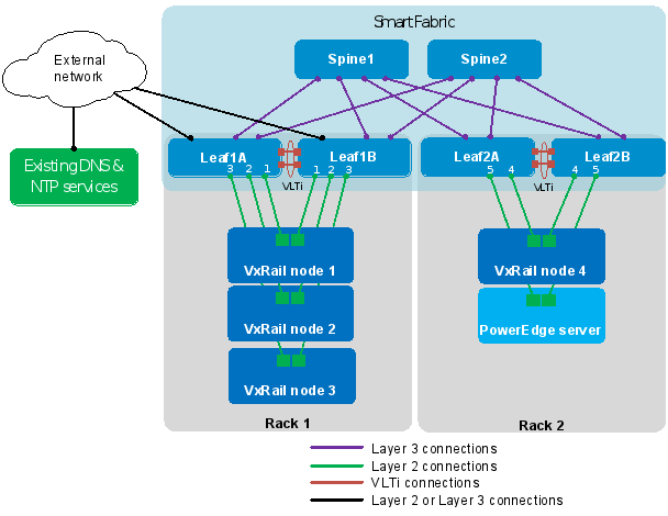
Figure 106. Non-VxRail device connected to SmartFabric
Add a server to the fabric
The PowerEdge server to be added is connected to Leaf2A and Leaf2B in this example, as shown in Figure 106.
Note: If the server uses a 1GbE or 10GbE NIC, and it is connected to 25GbE ports on S5200 series switches, the corresponding leaf switch ports used must be changed from 25GbE to 10GbE before proceeding. See Change native port speed on S5200 series switches for details.
In this example, the server's two connected ports are configured as an LACP NIC team in the operating system running on the PowerEdge server. An IP address is assigned to the NIC team on VM_Network_A, 172.18.14.0/24.
Note: NIC teaming and IP address configuration procedures on the PowerEdge server are dependent on the operating system used and are not covered in this guide.
To onboard the server to the SmartFabric using OMNI, do the following:
- In the vSphere Client, select Menu > OpenManage Network Integration.
- In the left pane, select the Service Instance.
- In the right pane, select Server Interface. The automatically configured VxRail node interfaces are listed with their MAC addresses used as the Server Interface IDs, as shown in Figure 107.
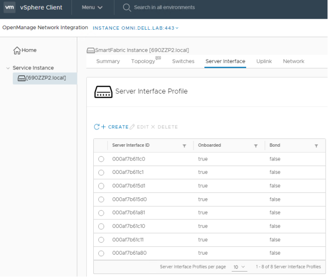
Figure 107. Server Interfaces
- Click CREATE.
- In the Create Server Interface Profile window that opens, do the following
- Enter a name for the Server Interface ID, for example, LACP NIC Team-1.
- Next to Server Profile, select New Server Profile.
- Enter a Server Profile ID, for example, PowerEdge Server 1.
- Next to Server Profile Bonding Type, select AutoDetect from the drop-down list.
- Next to Untagged Network, select a network for this connection from the drop-down list. In this example, it is VM_Network_A 1814.
- Next to Static Onboarding Option, select Yes.
- Select the Leaf Node and the Interface that is connected to the server. In this example, Leaf2A and ethernet 1/1/5:1 are selected.
- Leave Routing Protocol set to None.
The Create Server Interface Profile window appears, as shown in Figure 108.

Figure 108. Create a server interface profile
- Click CREATE.
Repeat steps 4-5 above for the second connection to the PowerEdge server using the values in Table 12.
Table 12. Values for second PowerEdge Server connection
Field
Value
Server interface ID
LACP NIC Team-2
Server Profile
Existing Server Profile
Server Profile ID
PowerEdge Server 1
Untagged Network
VM_Network_A 1814
Static Onboarding option
Yes
Leaf Node
Leaf2B
Interface
ethernet 1/1/5:1
Routing Protocol
None
When complete, the Server Interface Profile page appears, as shown in Figure 109.
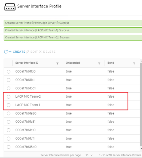
Figure 109. Server interface profiles created
Validation
Validation may be done at a leaf switch CLI with the following commands:
show port-channel summary
The show port-channel summary command output shows the newly created port channel, port channel 1, on interface 1/1/5:1. (P) indicates the member is up and active.
Note: In the output below, port channels 98-99 are SFS-configured uplinks to the spines, and port channel 1000 is the VLTi.
S5248F-Leaf2A# show port-channel summary
Flags: D - Down I - member up but inactive P - member up and active
U - Up (port-channel) F - Fallback Activated
--------------------------------------------------------------------------------
Group Port-Channel Type Protocol Member Ports
--------------------------------------------------------------------------------
1 port-channel1 (U) Eth DYNAMIC 1/1/5:1(P)
98 port-channel98 (U) Eth STATIC 1/1/56(P)
99 port-channel99 (U) Eth STATIC 1/1/55(P)
1000 port-channel1000 (U) Eth STATIC 1/1/49(P) 1/1/50(P) 1/1/51(P) 1/1/52(P)
show virtual-network
The show virtual-network output shows that port channel 1, containing the interface to the PowerEdge server, has been added as an untagged member of virtual network 1814.
Note: Other virtual networks have been removed from the output for brevity.
S5248F-Leaf2A# show virtual-network
Codes: DP - MAC-learn Dataplane, CP - MAC-learn Controlplane, UUD - Unknown-Unicast-Drop
Virtual Network: 1814
VLTi-VLAN: 1814
Members:
Untagged: port-channel1
VLAN 1814: port-channel1000, ethernet1/1/4
VxLAN Virtual Network Identifier: 1814
Source Interface: loopback2(172.30.0.1)
Remote-VTEPs (flood-list): 172.30.0.0(CP)
Ping host from onboarded server
The configuration may also be verified by pinging a host on the same virtual network as the newly onboarded server. In this case, the target host is a VM running on a VxRail node, is on VM_Network_A, VLAN 1814, and is at 172.18.14.1.
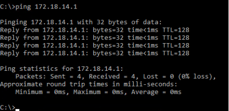
Figure 110. Added PowerEdge server pings a VM