
F5 BIG-IP DNS
F5 BIG-IP DNS
-
F5’s BIG-IP DNS can provide all of an organization’s DNS-related services. This paper focuses on how BIG- IP DNS can provide Global Server Load Balancing (GSLB). GSLB enables geographically distributed applications to scale and perform efficiently. It also allows applications to use a single endpoint regardless of their location. Figure 33 below shows a deployment example where BIG-IP DNS’s delegation mode is used. In the deployment example, two BIG-IP DNS, one at each of two sites, are configured to provide authoritative DNS answers for a subdomain named f5-ecs. This is a subdomain of the primary domain named ecstme.org which is used in a lab for this example.
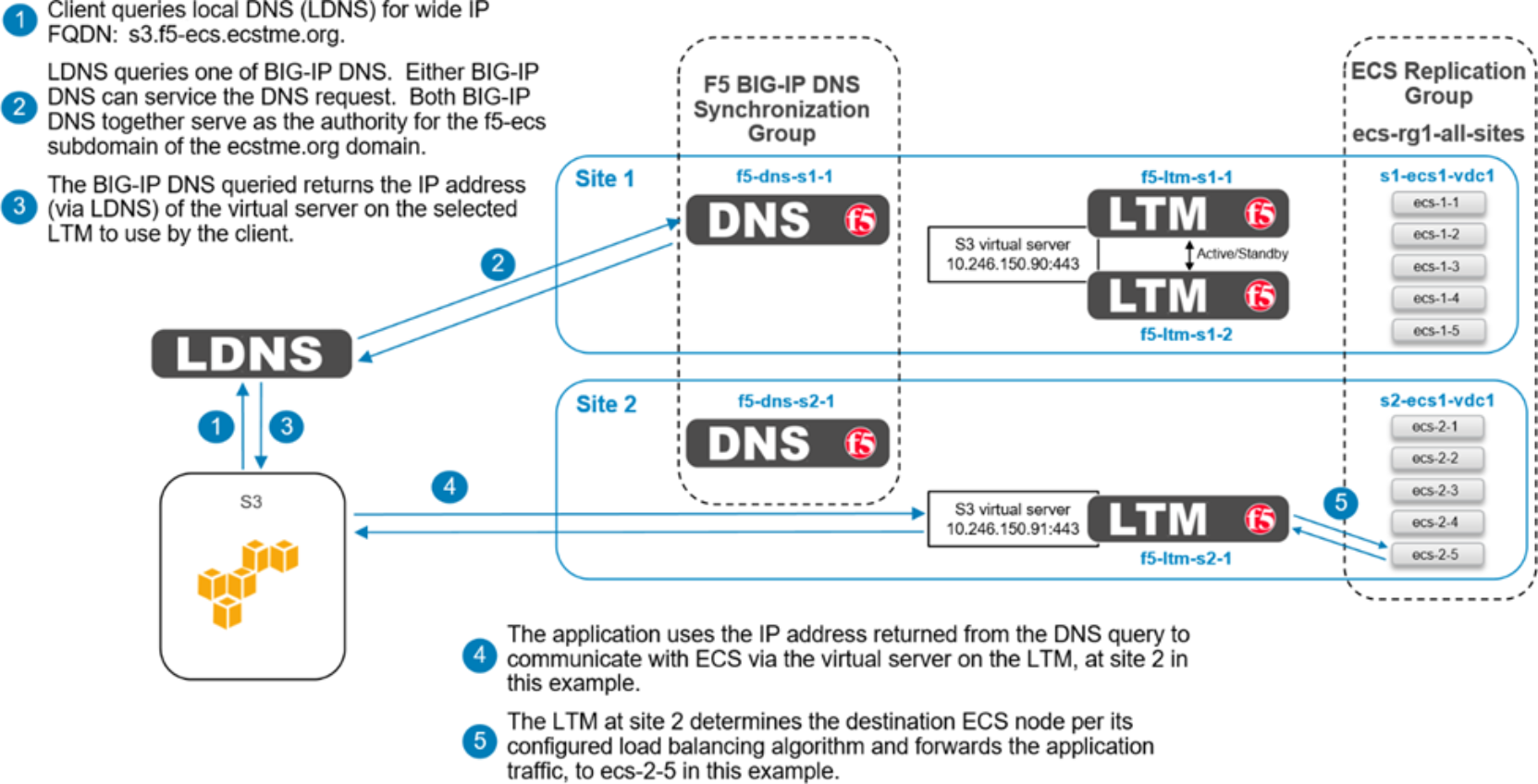
Figure 33. BIG-IP DNS high-level delegation mode overview
Introducing a BIG-IP DNS system in to an existing DNS architecture, as we are in this example, can be minimally disruptive because it requires little interaction with the existing authoritative architecture. A local DNS (LDNS) server is solely responsible for the domain ecstme.org and an associated /24 IP address space. The LDNS server is configured to delegate authority for a sub-domain named f5-ecs.ecstme.org. This is done by creating an NS record in the ecstme.org domain.
Each of the two BIG-IP DNS systems in this example requires a DNS A record in the primary domain. The server’s A records are associated with the NS record for the delegated namespace, f5-ecs.ecstme.org. With this setup, any DNS query inside the f5-ecs.ecstme.org sub-domain is forwarded to one of the two BIG-IP DNS systems for resolution.
Table 14 below show the required DNS entries for this example.
Table 14. DNS entries
DNS record entry
Record type
Record data
Comments
f5-dns-s1-1.ecstme.org
A
10.246.150.83
BIG-IP DNS self IP address Site 1
f5-dns-s2-1.ecstme.org
A
10.246.150.84
BIG-IP DNS self IP address Site 2
f5-ecs.ecstme.org
NS
f5-dns-s1-1.ecstme.org
BIG-IP DNS name server record Site 1
f5-ecs.ecstme.org
NS
f5-dns-s2-1.ecstme.org
BIG-IP DNS name server record Site 2
CNAME records can optionally be created to redirect DNS requests to the BIG-IP DNS for resolution. Our example deployment does not use CNAMES. Some organizations prohibit the use of CNAME records as they can complicate DNS administration in large scale environments. Also the use of CNAME records for heavily used names cause an extra redirect and lookup in the DNS resolution path which can result in undesirable latency.
A main benefit for using a BIG-IP DNS system is that it allows one namespace to be used by clients regardless of the number of end sites. For example, if three VDCs exists at geographically separate locations, and each VDC is served by one or more BIG-IP LTM, all users regardless of their location can use a single name, for example, s3.f5-ecs.ecstme.org. The BIG-IP DNS directs clients to the recommended, and available, ECS site by returning the IP address of the virtual server on the LTM the client should use.
In HA scenarios with BIG-IP DNS devices, only the Active/Standby type is available. That is if two BIG-IP DNS devices are to be deployed at a site in a redundant pair, they must be in the Active/Standby type of configuration. Globally however multiple BIG-IP DNS systems can all actively receive DNS requests from local DNS systems by participating in a synchronization group. This is how the two BIG-IP DNS systems are deployed in this example. One BIG-IP DNS system is deployed at each site. Both BIG-IP DNS systems are in a common synchronization group. The nameserver for the primary domain, ecstme.org, upon receiving a query for an address inside the f5-ecs subdomain, will forward that query to one of the two BIG-IP DNS systems. Each of the BIG-IP DNS systems serve as authority for the f5-ecs subdomain. Members of the synchronization group communicate with each other to ensure they’re all in agreement with the latest information.
The first step in BIG-IP DNS configuration involves creating data centers. Two data centers are created on each BIG-IP DNS instance in the deployment example, one for each site.
Figure 34 below shows the data centers as created on one of the BIG-IP DNS systems.
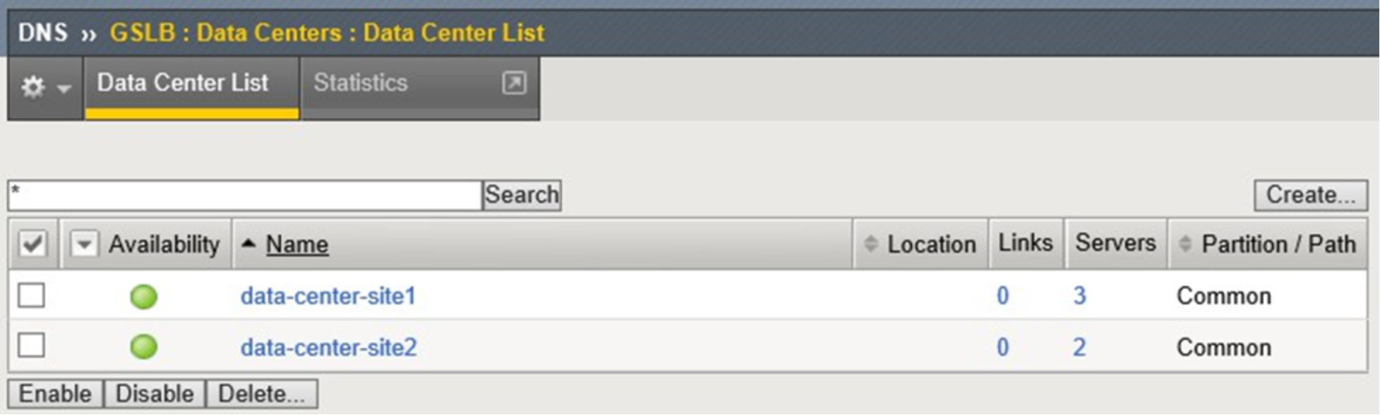
Figure 34. BIG-IP DNS configured data centers
Creation of data centers is simple and only requires naming of the instance. Optionally a prober preference can be set. In the deployment example, the prober preference was set to ‘Inside Data Center’ for the local-to- the-BIG-IP-DNS data center and ‘Outside Data Center’ for the data center created for the other site.
Data centers are populated with server objects. Server objects represent each of the BIG-IP systems on the network. It is possible to create server objects for third party systems as well. BIG-IP DNS server objects are created for each of the BIG-IP DNS and LTM systems in the deployment example. Self IP addresses of the BIG-IP systems are used during creation, not the management IP addresses. More than one IP address can be used depending upon how the server interacts with the rest of the network.
Figure 35 below shows the configuration used for the BIG-IP DNS at site 2. Along with naming the instance, it is assigned to the appropriate data center and assigned the bigip health monitor.
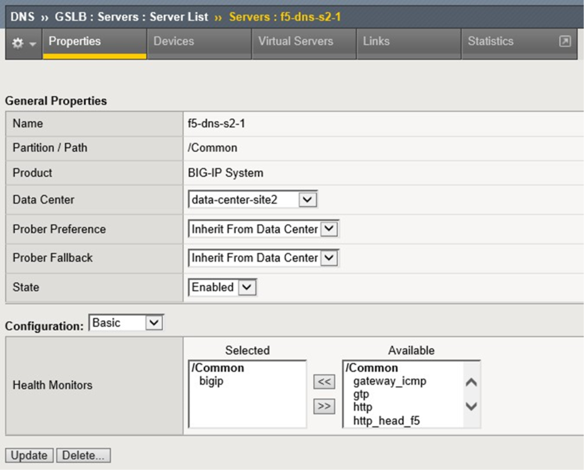
Figure 35. BIG-IP DNS server creation
Initially only the BIG-IP DNS system where the data center and server objects were created will show as available in the servers list in the WebUI. Access to the command line interface of this system is required for the next step where the big3d_install script is run. Running this script upgrades all BIG-IP system’s big3d agents and instructs the other systems to authenticate through the exchange of SSL certificates.
Example of the command run in our lab environment:
root@(f5-dns-s1-1)(cfg-sync In Sync)(Standby)(/Common)(tmos)# run gtm big3d_install 10.246.150.84 10.246.150.86 10.246.150.87 10.246.150.89
At this point in the configuration all BIG-IP systems can communicate with each other. The BIG-IP DNS systems can now use the other BIG-IP systems when load balancing DNS queries, and can acquire statistics and status information for the virtual servers these systems manage.
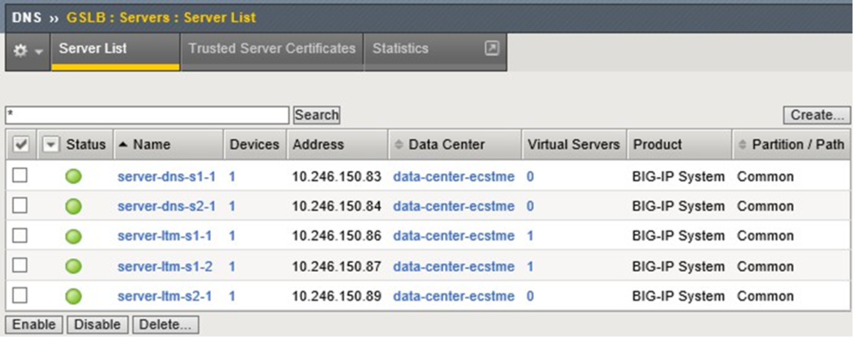
Figure 36. BIG-IP DNS server list
For the DNS-related configuration synchronization between BIG-IP DNS devices to occur, a synchronization group must be created and enabled. This is done on one of the BIG-IP DNS systems. Next, the other BIG-IP DNS system is configured to join the synchronization group. This is completed using the gtm_add script. The script is ran using a command line interface on the second BIG-IP DNS.
All BIG-IP DNS systems in the same BIG-IP DNS synchronization group have the same rank, exchange heartbeat messages, and share probing responsibility.
Below is output of the gtm_add script run in the deployment environment:
[root@f5-dns-s2-1:Standby:In Sync] config # tmsh
root@(f5-dns-s2-1)(cfg-sync In Sync)(Standby)(/Common)(tmos)# run gtm gtm_add 10.246.150.83
WARNING: Running this script will wipe out the current configuration files (bigip_gtm.conf, named.conf and named zone files) on the BIG-IP GTM Controller on which this script is run. The configuration will be replaced with the configuration of the remote BIG-IP GTM Controller in the specified sync group
The local BIG-IP GTM MUST already be added in the configuration of the other GTM.
NOTE: The current master key of this BIG-IP will be changed to match the master key of the remote BIG-IP GTM.
The BIG-IP config will be saved via: tmsh save sys config
after the master key is changed.
Are you absolutely sure you want to do this? [y/n] y
==> Running 'bigstart shutdown gtmd' on the local system
==> Running 'bigstart shutdown zrd' on the local system
==> Running 'bigstart shutdown named' on the local system Retrieving remote and installing local BIG-IP's SSL certs ...
Enter root password if prompted
The authenticity of host '10.246.150.83 (10.246.150.83)' can't be established. RSA key fingerprint is 5d:9b:7c:2a:0d:da:4e:17:64:16:1e:1a:32:56:e7:f5.
Are you sure you want to continue connecting (yes/no)? yes
Warning: Permanently added '10.246.150.83' (RSA) to the list of known hosts. Password:
Rekeying Master Key...
Saving running configuration...
/config/bigip.conf
/config/bigip_base.conf
/config/bigip_user.conf Saving Ethernet mapping...done
Verifying iQuery connection to 10.246.150.83. This may take up to 30 seconds Retrieving remote GTM configuration...
Retrieving remote DNS/named configuration...
Restarting gtmd Restarting named Restarting zrd
==> Done <==
Example: Roaming Client Geo Environment
BIG-IP DNS can be configured to direct traffic based on of the source of the DNS query. This allows applications to use common, global FQDNs, and have their traffic directed to the closest or best-performing destination resource.
Figure 37 shows an application physically located near Site 1. BIG-IP DNS can use the source address of the LDNS server that is resolving the FQDN on behalf of the client to determine which site is most appropriate for the application to be directed to.
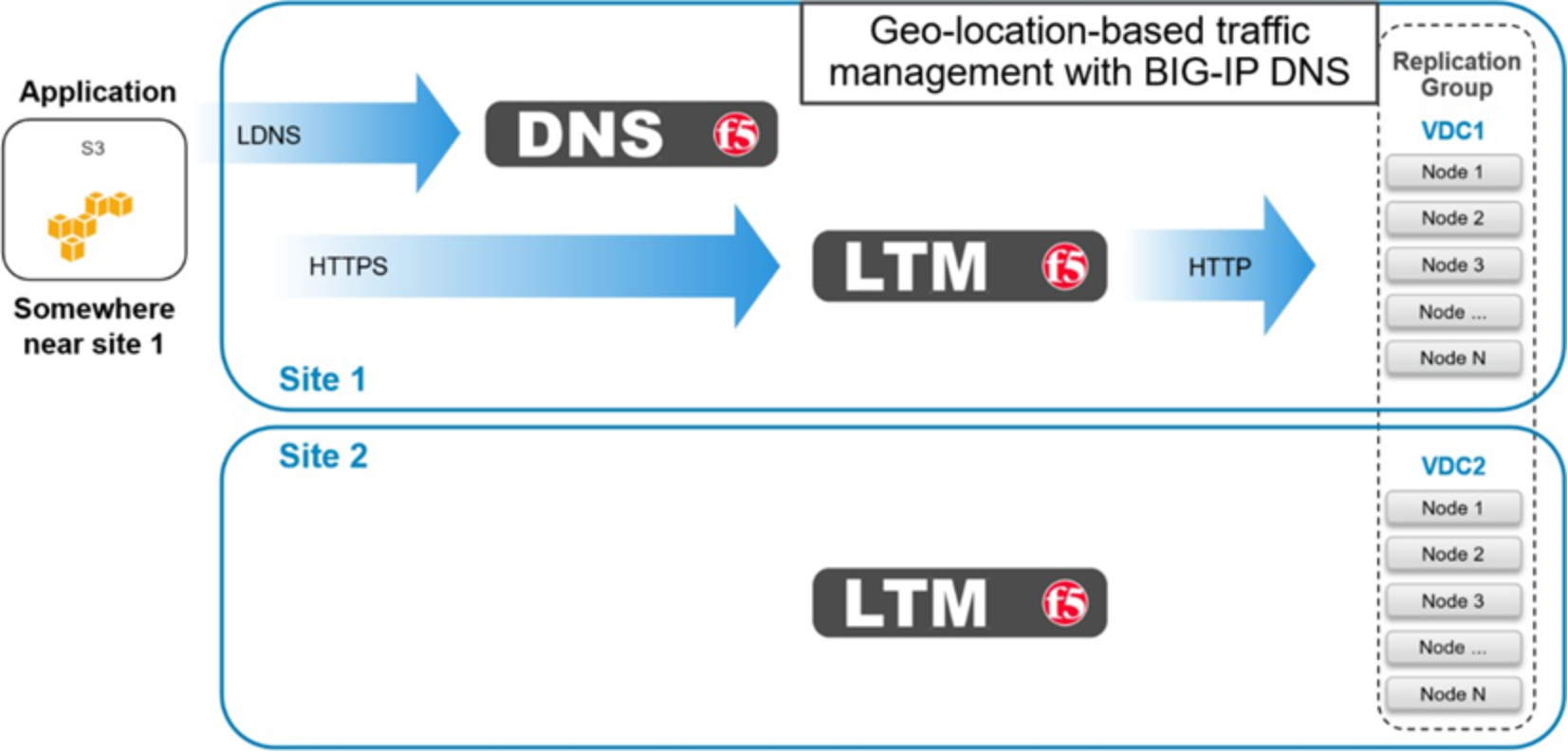
Figure 37. BIG-IP DNS roaming client near Site 1
Figure 38 shows an application physically near Site 2. BIG-IP DNS will resolve the DNS query to a virtual server located on the LTM at Site 2. This should provide the application with the path of the lowest latency.
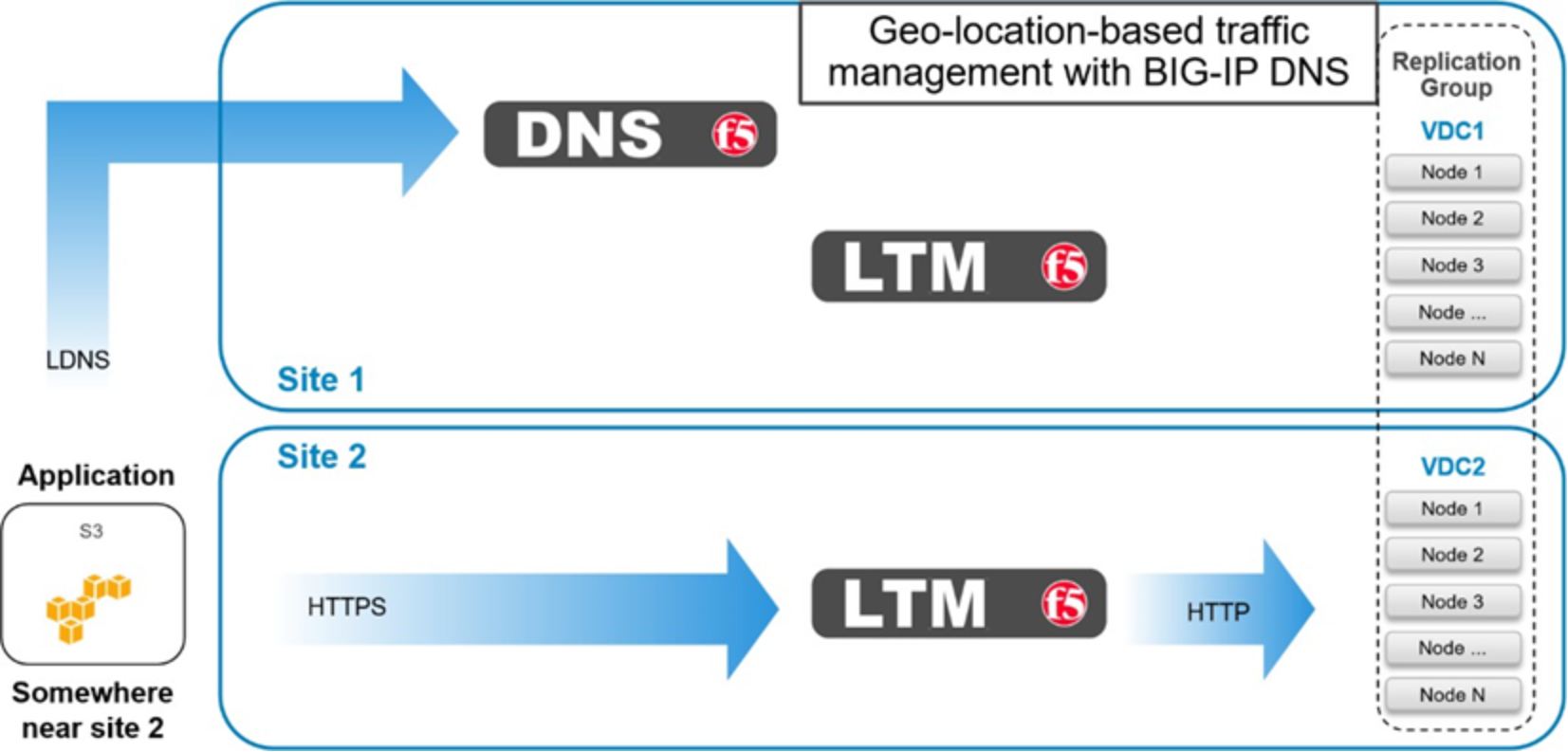
Figure 38. BIG-IP DNS roaming client near Site 2
Example: Application Traffic Management for XOR Efficiency Gains
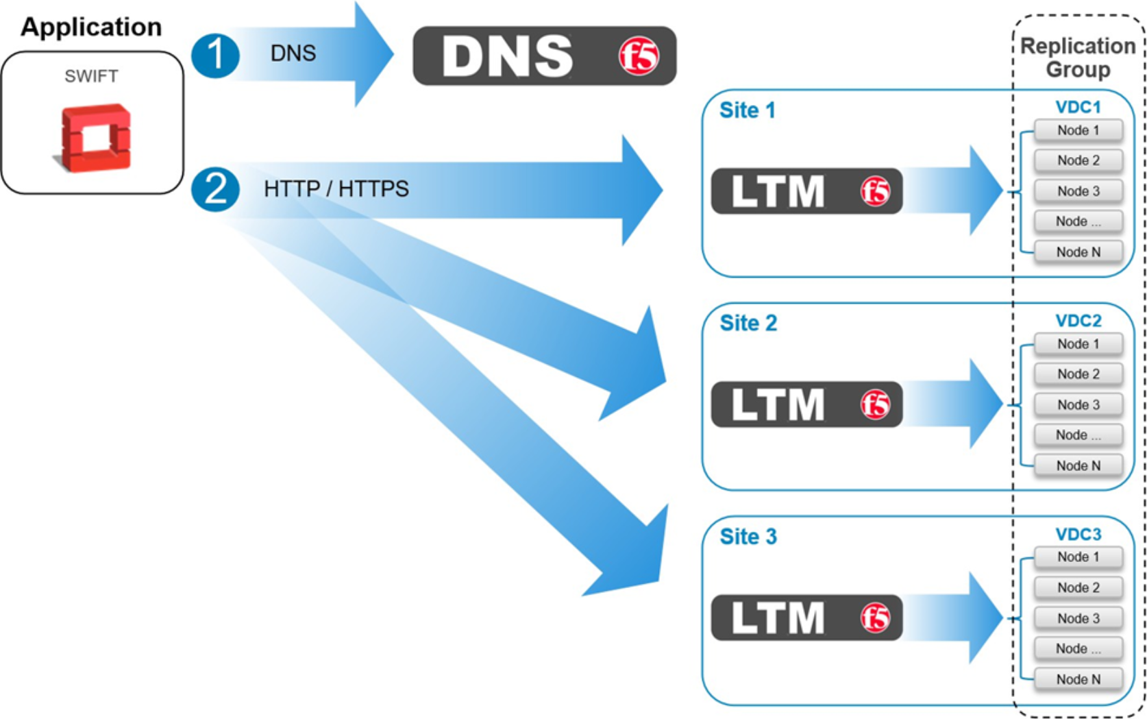
Figure 39. XOR efficiency gains using BIG-IP DNS
Data must be written across three or more sites in order to take advantage of the storage efficiencies gained on ECS by XOR. For workflows that can tolerate latencies associated with this traffic pattern, BIG-IP DNS can be configured to balance write traffic equally between sites in a round robin fashion.