
Logical architecture
Logical architecture
-
Figure 2 shows the Cloudera CDP logical architecture as deployed upon PowerFlex and PowerScale.
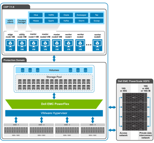
Figure 2. Logical architecture of CDP deployment on PowerFlex and PowerScale
The PowerFlex software-defined storage was configured in a VMware vSphere environment and deployed with a single-layer Hyperconverged Infrastructure (HCI) architecture option. The HCI configuration has both SDC and SDS software components that are configured on each node of the cluster. SDC provides the compute capabilities while SDS provides storage for CDP runtime components. The PowerScale scale-out network-attached storage (NAS) platform provides Hadoop clients with direct access to big data through a Hadoop File System (HDFS) interface. Powered by the distributed Dell EMC PowerScale OneFS operating system, a PowerScale cluster delivers a scalable pool of storage with a global namespace.
Hadoop compute clients access the data that is stored in a PowerScale cluster by using the HDFS protocol. Every node in the PowerScale cluster can act as a NameNode and a DataNode.
The first consideration for the implementation is the number of CDP clusters to be deployed. A common use case here is for Dev, UAT, and Prod Clusters. Each CDP cluster requires its own Access Zone on PowerScale, and its own pool of Linux VMs.
Networking design
The following figure shows the logical layout of PowerFlex rack access and aggregation with management aggregation architecture. From the different topologies below, Dell Technologies went with the Hyperconverged topology, mainly because of the small scale for the deployment.
In general, this decision should be made with the architecture endgame in mind. The amount of local storage that the VMs require is typically 10% to 20% of the usable HDFS storage. If the final solution needs 1 PB of HDFS storage, then the local storage would be at most 200 TB. The storage must be distributed across the PowerFlex nodes. If the final PowerFlex number was 20 nodes, then 10 TB per node seems easy enough for an HCI topology.
Note: There is an additional 1 Gb link from the PowerFlex controller nodes to the out-of-band management switch.
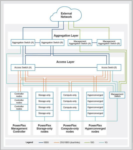
Figure 3. PowerFlex rack access and aggregation architecture
PowerFlex design
The Storage Data Server (SDS) aggregates the raw local storage in a node and serves it up as PowerFlex storage. A single protection domain is carved out of the SSD drives on the four PowerFlex hyperconverged nodes. A single storage pool is configured, and multiple volumes were carved out to meet the CDP requirements. These volumes are mapped to the ESXi cluster and added as a datastore. They are later mapped as disks drive to Hadoop virtual machines using VMware Paravirtual SCSI (PVSCSI) adapters.
Table 4. PowerFlex storage details for CDP virtual machines
VM
Operating system
Data1
Data2
Master [1-3], Utility, Edge
500 GB
N/A
N/A
Worker [1-5]
500 GB
1 TB
1 TB
Note: Worker nodes require local storage for shuffle, Spark cache, and other functions. Dell Technologies recommends using the PowerFlex storage for this configuration. Leveraging two devices provides a good balance for simplicity, resiliency, and performance.
PowerScale design
SmartConnect is a module that specifies how the OneFS cluster handles connection requests from clients. For more information and best practices for SmartConnect, see the Isilon External Network Connectivity Guide.
Each SmartConnect zone represents a specific pool of IP addresses. You associate a SmartConnect zone with an access zone. OneFS then allows only clients that connect through the IP addresses in the SmartConnect zone to reach the HDFS data in the access zone. A root HDFS directory is specified for each access zone. This configuration isolates data within access zones and allows you to restrict client access to the data.
CDP virtualization design
The CDP cluster environment consists of multiple software services running on multiple virtual machines. The implementation divides the server VMs into several roles, and each VM has a configuration that is optimized for its role in the cluster.
The VM configurations are divided into two broad classes:
- Worker VMs - Worker VMs handle the bulk of the Hadoop processing.
- Master VMs - Master VMs support services that are needed for the cluster operation.
Table 5. VM configurations
VM
vCPU
Memory
Master [1-3]
12
64 GB
Utility
4
16 GB
Edge
2
16 GB
Worker [1-5]
16
175 GB
Note: Dell Technologies does not recommend overcommitting the memory.
Table 6. VM definitions
VM
Count
Definition
Master
3
Runs all the daemons that are required to manage the cluster
storage and compute services
Worker
5
Runs all the services that are required to store blocks of data
on the local hard drives and run processing tasks against that data
Edge
1
Runs Cloudera Manager and the Cloudera Management
services
Utility
1
Contains all client-facing configurations and services, including
gateway configurations
VMware considerations
The choice of which flavor of VM should be mapped to which physical host is a dynamic decision. The HDFS data can be accessed from any physical node, and the runtime storage on PowerFlex can also be accessed from any physical node. This design provides flexibility in VM placement since vMotion can be used to migrate VMs at any time to alleviate hotspots and or perform node maintenance. The design also provides flexibility in VM sizing, allowing the VM configurations to be changed based on workload requirements.
For the architecture testing, Dell Technologies chose a simple deployment scenario using four physical PowerFlex nodes and ten virtual machines with fixed mapping of VMs to physical nodes. See Table 7, VM services.
Table 7. VM services
VM
CDP service
PowerFlex physical node number
Master VM1
FailoverController, YARN ResourceManager, ZooKeeper, JobHistory Server, Spark History Server, Kudu master
Node-1
Master VM2
FailoverController, YARN ResourceManager, ZooKeeper, JobHistory Server, Spark History Server, Kudu master
Node-3
Master VM3
ZooKeeper, Kudu master (All require an odd number of masters for high availability.)
Node-4
Utility VM
Cloudera Manager, Cloudera Management Service, Hive Metastore, Impala Catalog Server, Impala StateStore, Oozie, ZooKeeper (Requires a dedicated disk), Apache Atlas, Apache Ranger
Node-3
Edge VM
Hue, HiveServer2, Gateway configuration
Node-1
Worker VM [1-5]
NodeManager, Impalad, Kudu tablet server
Node-1, Node-2 (two workers), Node3, Node-4
Note: Unlike standard CDP installations, the Master VMs do not run Cloudera NameNode processes, and the Worker VMs do not run DataNode processes. The PowerScale HDFS protocol provides these services.