
VxRail vDS with NSX networks
VxRail vDS with NSX networks
-
VxRail vDS and predefined network profiles
If a single vDS is used for the deployment, all system traffic and NSX traffic share the same vDS. There are four predefined VxRail vDS network profiles for the deployment, two uplinks with 2x10 GbE, two uplinks with 2x 25 GbE, four uplinks with 4x10, and four uplinks with 4x25 profiles. A two-uplink profile can either be 2x10 or 2x25. The following figures illustrate the 2x10/2x25 and 4x25 predefined profiles:
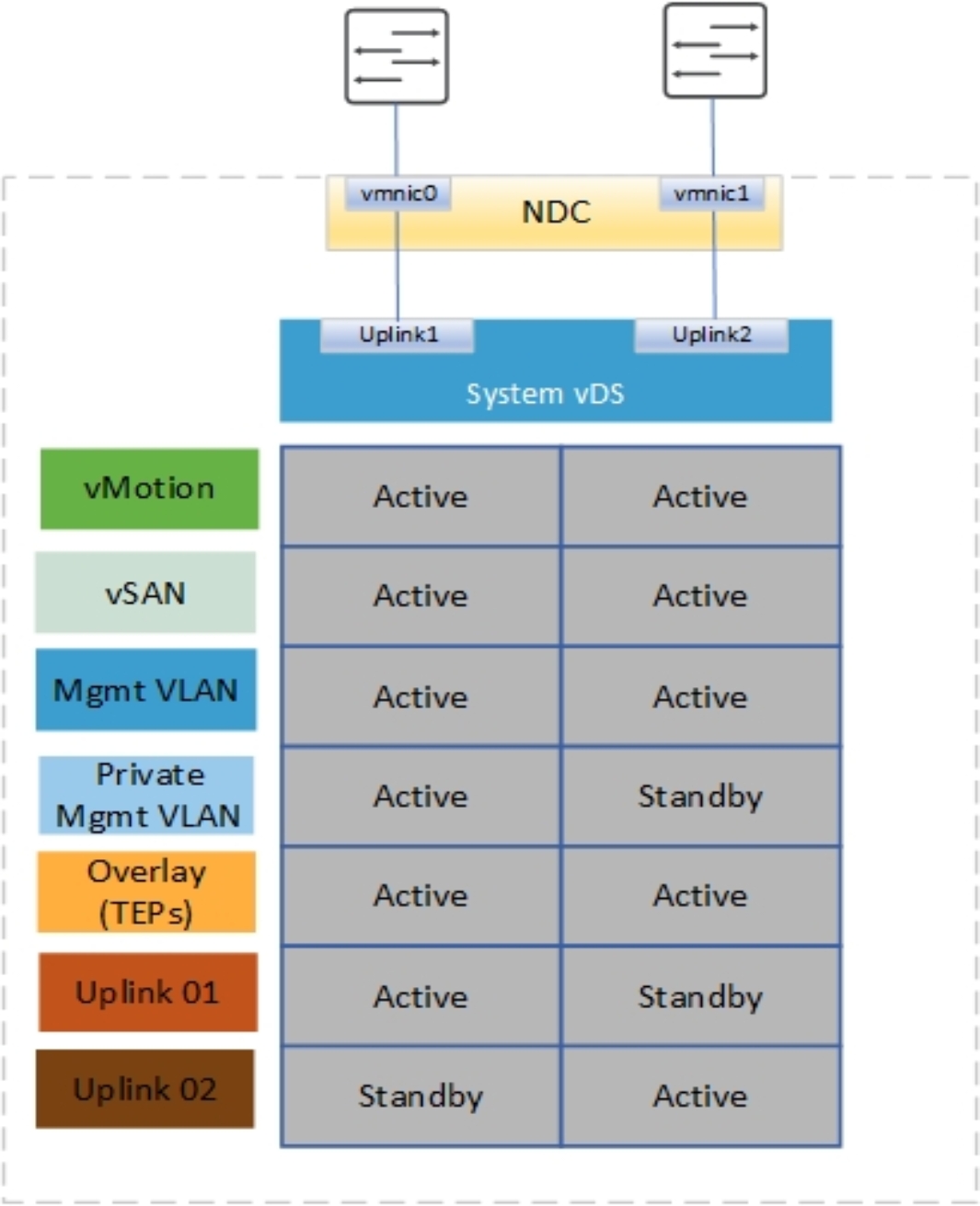
Figure 13. Single vDS using 2x10/2x25 predefined network profile
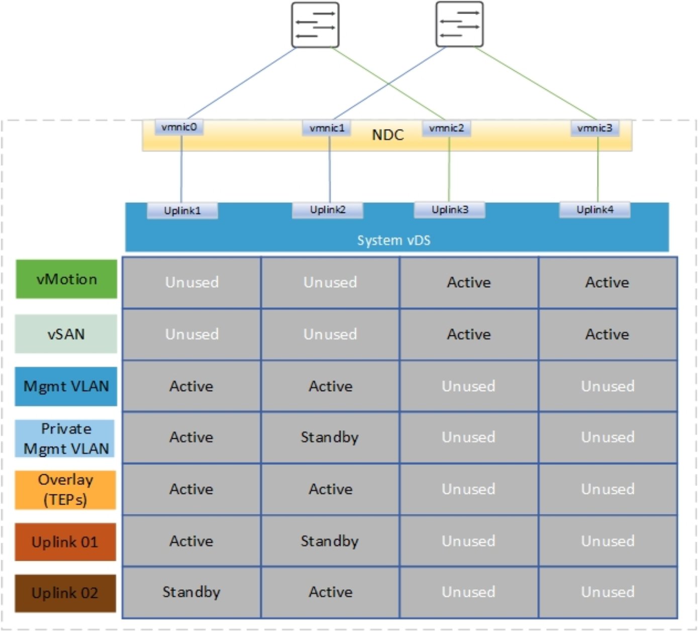
Figure 14. Single vDS with 4x10 predefined network profile
The following figure illustrates the 4x25 profile that was introduced in VxRail version 7.0.100. The profile uses both an NDC/OCP and PCIe to achieve NIC-level redundancy for the system traffic. From 7.0.130 onward, using this profile is not recommended because it results in a nonstandard wiring configuration, as shown in the figure:
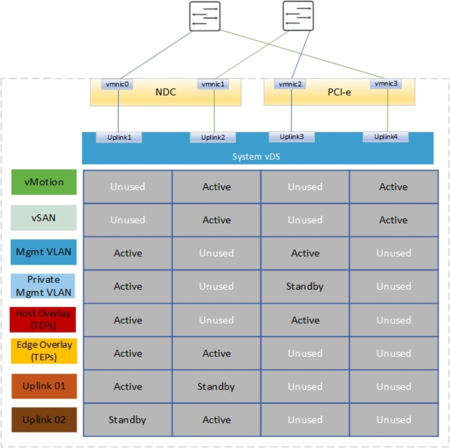
Figure 15. Single vDS with 4x25 predefined network profile
Notice that in the previous figure, the cabling of the NIC ports to the switches is a little unorthodox. We normally have vmnic2 going to Fabric A and vminc3 going to Fabric B.
Note: Starting with VCF version 4.3, you can select the vmnics used for external Mgmt, vSAN, or vMotion to be used for the host TEP traffic and Edge traffic.
Starting with VCF 4.2 and VxRail 7.0.131, the recommended method to achieve NIC-level redundancy for a VCF on VxRail cluster with 4x25 GbE is to configure the custom profile for the VxRail vDS using the configuration of the vmnic/uplink mappings and the uplink to port group mapping shown in the following two tables. You must configure this profile when creating the json before the VxRail cluster deployment for any VCF clusters.
Table 6. VxRail vDS uplink to pNIC mapping
vDS uplink
Physical NIC
Uplink1
vmnic0 – NDC - port 1
Uplink2
vmnic3 – PCIe - port 2
Uplink3
vmnic1 – NDC - port 2
Uplink4
vmnic2 – PCIe - port 1
Table 7. VxRail vDS port group uplink mapping
Port group
Teaming policy
Active
Standby
VxRail Management
Route based on the originating virtual port
Uplink1
Uplink2
vCenter Server
Route based on the originating virtual port
Uplink1
Uplink2
External Management
Route based on Physical NIC load
Uplink1
Uplink2
vMotion
Route based on Physical NIC load
Uplink3
Uplink4
vSAN
Route based on Physical NIC load
Uplink3
Uplink4
Note: During VCF deployment of management WLD or when a VxRail cluster is ingested into a VI WLD, all port groups are configured as active/active except VxRail management, which remain active/standby.
The configuration of the vDS and uplink to pNIC mapping that is shown in the following figure provides NIC-level redundancy for a 4x25 GbE deployment using the VxRail custom profile feature in 7.0.131.
Note: The uplink to vmnic mappings on the vDS as a misconfiguration could cause a deployment failure.
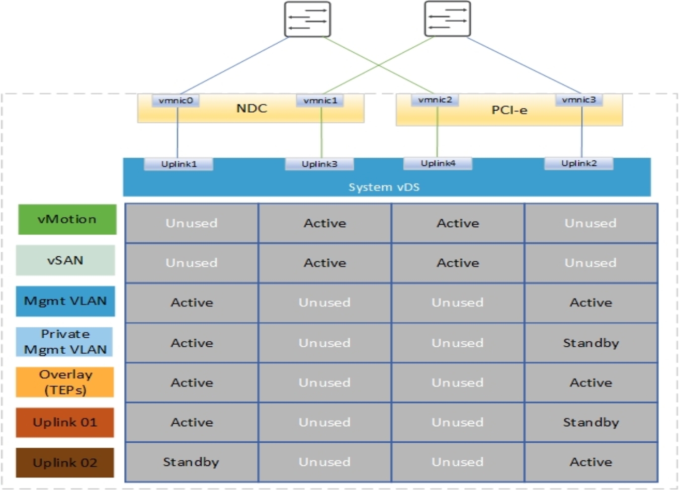
Figure 16. Single vDS with 4x25 using custom profile
Note: The preceding design can also be achieved using 10 GbE network cards when a custom profile is used to create the configuration.
Another variation of the preceding design is to separate vSAN onto a dedicated pair of physical NICs or a different pair of TOR switches. This separation ensures that maximum bandwidth can always be allocated to vSAN traffic. This design requires one change in the custom profile, where vMotion would use uplink1/uplink2, leaving vSAN only using uplink3/uplink4.
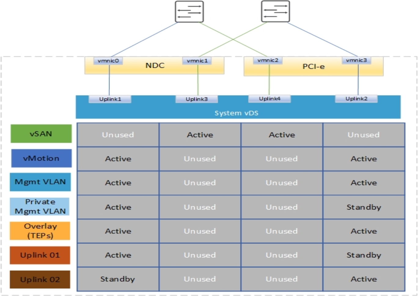
Figure 17. Two vDS with custom profile and NIC-level redundancy