
System installation and configuration
System installation and configuration
-
ESXi system configuration
Use the following steps to configure the physical servers that host the database VMs:
- Use the BIOS settings for the PowerEdge servers described in Table 6.
- Create a single virtual disk in a RAID 1 configuration with two local disks (SSDs or HDDs) per server to install the bare-metal operating system (ESXi 7.3).
- Install ESXi 7.3 by using the Dell customized ISO image.
- Configure, monitor, and maintain the ESXi host, virtual networking, and the VM by using the VMware vSphere web client and VCSA, which is deployed as a VM on the management server.
- Zone two dual-port 32 Gb/s HBAs (four initiators total) and configure these HBAs with the PowerStore front-end Fibre Channel ports for high bandwidth, load-balanced, and highly available SAN traffic.
PowerStore storage configuration details
In the baseline configuration for the Oracle database storage volumes and related VM operating system storage volumes, we applied the following design principles to create volumes:
- VM storage group (Salt_VM_OS) has two volumes: one volume per VM Linux Guest operating system
- GRID storage group (Salt_VM_GRID) has 2x3 volumes: three volumes for ASM instance parameter file and password file. Although we used the normal redundancy setting, an alternative option is to use the external redundancy setting by only having one volume for each disk group.
- Two Database storage groups (Salt_DB1 and Salt_DB2): each database storage group consists of all the volumes for this database (one DATA volume, one REDO volume, and one FRA volume).
- TEMP storage group (Salt_VM_TEMP) has two volumes: each is for the TEMP volume of a database.
Table 7. PowerStore storage volumes
VolumeGroup
VolumeName
Volume Size(GB)
Purpose
Salt_VM_OS
Salt_VM_OS-001
300
Guest VM1 OS
Salt_VM_OS-002
300
Guest VM2 OS
Salt_VM_Grid
Grid_VM1-(001-003)
3x50
ASM instance parameter file and password file of VM1
Grid_VM2-(001-003)
3x50
ASM instance parameter file and password file of VM2
Salt_DB1
DB1_Data-001
1200
Data for VM1
DB1_Redo-001
60
Redo for VM1
DB1_Fra-001
50
FRA for VM1
Salt_DB2
DB2_Data-001
1200
Data for VM2
DB2_Redo-001
60
Redo for VM2
DB2_Fra-001
50
FRA for VM2
Salt_VM_Temp
Salt_Temp-001
500
Temp for VM1
Salt_Temp-002
500
Temp for VM2
SAN FC network zoning configuration
There are four front-end I/O modules per node in PowerStore storage system. R750 servers have four HBA ports. Each front-end module and server side HBA port includes a 32 Gbps Fibre Channel.
For the baseline SAN configuration, the HBA ports (initiators) of R750 server and storage front-end I/O modules (targets) are connected to a switch. A storage zone process pairs the HBA ports and storage front-end ports. Each of the pairs create a physical path between the server and the storage. In the baseline configuration we used two HBA ports for each R750 server and two storage front-end modules per node. We paired each HBA port with one PowerStore controller node port, as shown in Figure 2.
This configuration ensures high availability against a single component failure of the stack.
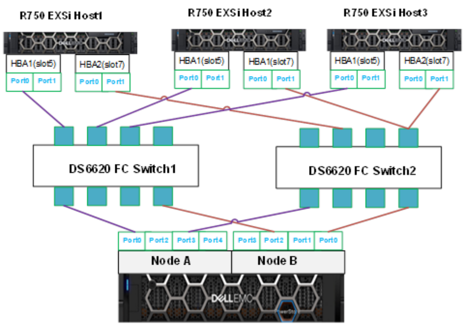
Figure 2. Baseline SAN FC connectivity and zoning
VM network: Distributed Network switches
We configured the following two distributed network switches:
- ESXI-Mgmt DS ESXi server management that connects to the vCenter and ESXi hosts
- OraPub-vMotion that supports the VM network for Oracle database public network and vMotion.
The following table shows the details of these two distributed network switches.
Table 8. Distributed network switches
Distributed network switches
Uplink ports
Purpose
VM port group
ESXI-Mgmt DS
On 2x 1GB network (rNDC) vmnic0 and vmnic 1
ESXi server host management
OraPub-vMotion
2x25 GbE physical network: vmnic5 and vmnic11
Oracle Database public network and vMotion network
OraPub
Table 9. VMware Network settings
Network Settings
Jumbo Frames
Disabled
VMXNET2 adapter
Yes
Server Physical NIC port and HBA Port and Switch connectivity
The following table shows the physical NIC ports, their associated switches, and port groups. The last two columns, SAN FC A and SAN FC B, are the two dual port HBAs that are connected to the Fibre channel switches. The last row describes the switch ports that are connected the corresponding NICs ports or the HBA ports.
Table 10. Switches ports, NIC ports and HBA ports in Ethernet network and SAN FC network
Server
ESXi Mgmt Network
Oracle Pub Group
vMotion Network
SAN FC A
SAN FC B
R750-92O-09
vmnic0(e:1), vmnic1(e:2)
vmnic2(i:1)
vmnic4(2:1)
1:1, 7:1
1:2, 7:2
R750-92O-11
vmnic0(e:1), vmnic1(e:2)
vmnic2(i:1)
vmnic4(2:1)
1:1, 7:1
1:2, 7:2
R750-92O-13
vmnic0(e:1), vmnic1(e:2)
vmnic2(i:1)
vmnic4(2:1)
1:1, 7:1
1:2, 7:2
Switch Ports
L42K-92O-SW1:10 On L45K-98Q-SW01 Fex 132 (ACCESS VLAN 379)
S5224-92O-40:11 (TRUNK VLAN 382, 99)
S5224-92O-40:11 (TRUNK VLAN 382, 99)
DS6620-92J:1:8
DS6620-92J:2:8
Figure 3 shows the configuration of the physical and virtual network and theandSAN Fibre Channel Network. In the middle of figure, two virtually distributed switches established the mapping of the virtual network port groups and physical uplinks:
- Distributed switch vDS-01-ESXi-Mgmt connects the port group ESXi-Mgmt-3780dPG and the two physical uplinks vmnic0 and vmnic1.
- Distributed switch vDS-02-Orapub-Vmotion connects two port groups: pub-25GbE-vlan382-dPG (for VM public network) and vMotion-25GBE-vlan99-dPG (for Motion) with two physical uplinks vmic2 and vmnic4.
- The right side of the figure shows how these physical links are mapped to the physical NIC ports of each server and how these NICs ports are connected to the 25GBE TOR physical switches that connect to outside network.
- The lower right side of the figure shows how the two dual ports HBAs are connected to the ports of two FC switches.

Figure 3. Physical and virtual network design