
Physical architecture
Physical architecture
-
Physical architecture overview
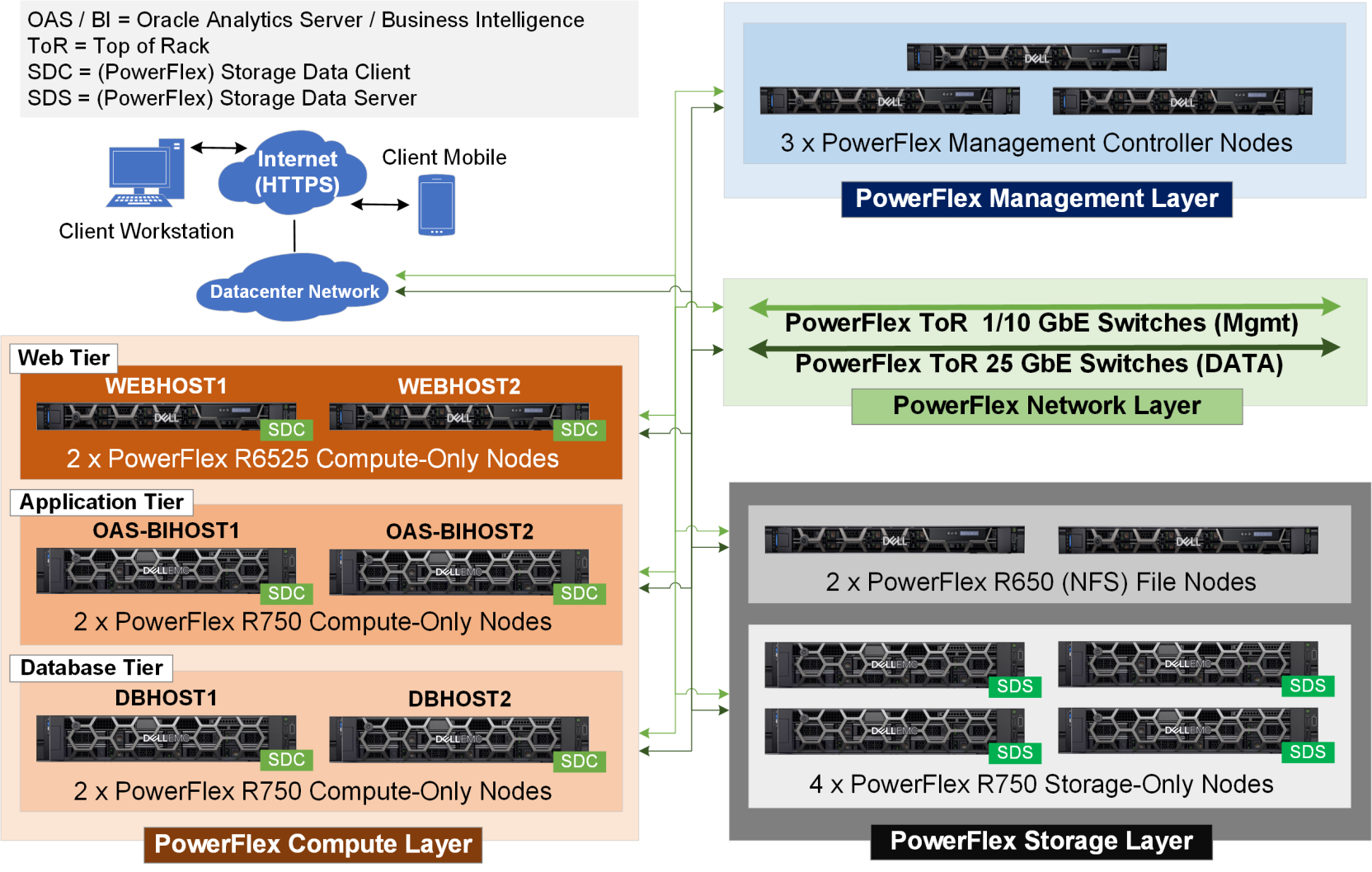
Figure 2 shows the three-tier physical architecture of the Oracle Analytics Server enterprise solution deployed on Dell PowerFlex as the underlying hardware infrastructure.
PowerFlex supports deploying the SDS and SDC as:
- Single-layer Hyper Converged Infrastructure (HCI): Here SDS and SDC run on the same set of nodes.
- Traditional two-layer infrastructure: Here SDS and SDC nodes are deployed separately as storage-only nodes and compute-only nodes, respectively.
- Mix-layer infrastructure: Here we have a mix of both single-layer HCI and two-layer deployment of the SDS and SDCs.
For an OAS enterprise solution, we recommend deploying a two-layer PowerFlex 4.0 infrastructure as shown in Figure 2 where the storage-only nodes (SDS) are deployed separately to the compute-only nodes (SDC). This two-layer PowerFlex deployment architecture provides the benefit to independently scale-out any of the OAS tier’s compute hosts, as need arises to service larger requests with growing number of users and/or data sources. It also provides the flexibility to independently scale-out the storage needs, both in terms of the storage capacity and performance.
OAS and PowerFlex compute layer
As shown in the PowerFlex Compute Layer section of the Figure 2, each of the physical servers or hosts required in the three tier OAS architecture is deployed as a PowerFlex SDC node. In each OAS compute tier, we deployed two physical hosts – two web tier hosts, two application tier hosts, and two database tier hosts – for high availability and performance.
In our design, the web tier hosts are virtualized in order to run both the virtual load balancers and the web servers. Hence, for high availability and computing resource needs, we deployed two PowerFlex R6525 compute-only nodes as the web tier hosts (WEBHOST1 and WEBHOST2) that are powered by two 3rd generation AMD EPYC processors.
OAS enterprise deployment requires that we build an OAS or BI domain cluster using two or more highly available BI physical hosts. The OAS cluster startup, data visualization, and analyses performance is majorly determined by the CPU, memory, network, and local storage resources of the BI hosts and the backend database hosts. To meet these OAS performance and high availability requirements, each of the hosts in the application tier (OAS-BIHOST1 and OAS-BIHOST2) and the database tier (DBHOST1 and DBHOST2) are deployed using the PowerFlex R750 compute-only nodes that are powered by two 3rd Generation Intel Xeon processors. For details on each of the host components, see Table 9 in the Appendix.
OAS and PowerFlex storage layer
For maximum availability, a highly available NAS and/or SAN based shared storage is recommended for the OAS enterprise deployment. One of the key advantages of using the Dell PowerFlex 4.0 infrastructure is that it supports and provides for both file-based (NAS) and block-based (SAN) storage needs of the OAS enterprise solution.
As shown in the PowerFlex Storage Layer section of the Figure 2 above, in our design, the OAS shared storage layer consists of four highly available PowerFlex R750 SDS or storage-only nodes and two highly available PowerFlex R650 File nodes. The PowerFlex File nodes provide the file-based storage needs and the PowerFlex SDS nodes provide the block-based storage needs for our OAS solution stack. For details of each of the storage node’s components, refer to Table 10 in the Appendix.
PowerFlex Network and Management Layer
In our design, the PowerFlex Network Layer consists of two top-of-rack (ToR) 25 GbE Cisco Nexus C93180YC-EX switches for the secure data traffic and 1 GbE Cisco Nexus C3172TQ-XL switches for the out-of-band management traffic. The PowerFlex Management Layer consists of the dedicated PowerFlex Management Platform (PFMP) deployed across three ESXi-based highly available PowerFlex Controller nodes. The PowerFlex 4.0 PFMP provides a unified web interface called the PowerFlex Manager to monitor and manage all the PowerFlex hardware resources that include the PowerFlex network switches, PowerFlex SDC nodes, PowerFlex File Nodes, and PowerFlex SDS nodes. The PowerFlex Manager also provides a single pane web interface to provision, manage, and monitor both block-based and file-based storage volumes.