
Network architecture and configuration
Network architecture and configuration
-
The design principles of the network configuration for the OAS enterprise deployment on Dell PowerFlex infrastructure involves configuring a high-bandwidth, high-performance, highly available, secure, and flexible network.
Physical network architecture
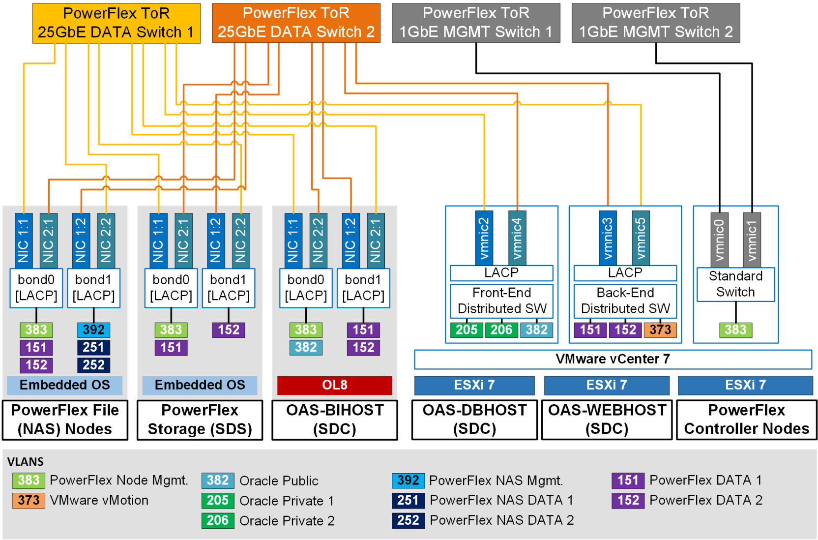
Figure 5. Network architecture of OAS enterprise deployment on Dell PowerFlex Infrastructure
Figure 5 shows the high bandwidth, highly available and secure physical network architecture implemented on each PowerFlex storage node (SDS and File), PowerFlex compute node (SDCs), and the PowerFlex Controller node that is part of the OAS enterprise solution stack.
For high availability, high bandwidth, and load balancing, within each node two 25 GbE ports from two different network adapters are bonded together with Link Aggregation Control Protocol (LACP). The network adapters in the PowerFlex storage nodes (SDS and File) get automatically configured during the PowerFlex 4.0 OS installation. The network adapters in the PowerFlex compute nodes (SDCs) were manually configured. For network performance and security, each type of network is segregated using tagged VLAN. The Table 2 below shows the list of networks used in the OAS enterprise solution deployment on the PowerFlex infrastructure with example tagged VLAN IDs associated with.
Table 2. List of networks used in the OAS enterprise solution deployment on PowerFlex Infrastructure
VLAN ID*
Network Type
Properties
Network Used
383
PowerFlex Management
Layer-3; MTU=1500
For PowerFlex systems management that includes PFMP VMs, PowerFlex Manager, PowerFlex SDS and SDC node management
151
PowerFlex Data 1
Layer-2; MTU=9216
For storage data traffic between all PowerFlex core components: SDS to SDS, SDC to SDS, and SDS to PowerFlex Manager
152
PowerFlex Data 2
Layer-2; MTU=9216
For storage data traffic between all PowerFlex core components: SDS to SDS, SDC to SDS, and SDS to PowerFlex Manager
392
PowerFlex NAS Management
Layer-3; MTU=1500
For file management traffic between SDS and Controller nodes
251
PowerFlex NAS Data 1
Layer-2/Layer-3; MTU=9216
For file data traffic between SDS and Controller nodes
252
PowerFlex NAS Data 2
Layer-2/Layer-3; MTU=9216
For file data traffic between SDS and Controller nodes
382
Oracle Public
Layer-3; MTU=1500/9216
For Oracle public traffic between Oracle applications (OHS, OAS, Oracle Database) across the three tiers (web, application, database)
205
Oracle Private Interconnect 1
Layer-2; MTU=9216
For Oracle private interconnect traffic between the Oracle RAC database nodes (VMs)
206
Oracle Private Interconnect 2
Layer-2; MTU=9216
For Oracle private interconnect traffic between the Oracle RAC database nodes (VMs)
373
VMware vSphere vMotion
Layer-2; MTU=9216
For VMware vSphere vMotion of any PowerFlex management VMs (on Controller nodes) and/or Application VMs (on ESXi-based SDCs)
Note: The listed VLAN IDs are only examples. Any appropriate VLAN IDs can be used.
The PowerFlex ToR switch ports that the storage and compute nodes connect to were configured as trunk ports to allow appropriate tagged VLANs to pass through. LACP was enabled on the switch ports to ensure proper handshake and connectivity happens only with the wanted server NIC ports (also configured with LACP).
As listed in Table 2 , for enhanced network performance jumbo frames (MTU=9216) were enabled end-to-end on the appropriate networks, spanning from the network ports on the storage/compute nodes to the switch ports at both the physical and virtual level.
Web tier network configuration
LBR network configuration
As required for the OAS enterprise solution, Figure 6 shows the three Virtual Server Names (called Virtual Services in VLM load balancer) we configured in the VLM web interface.
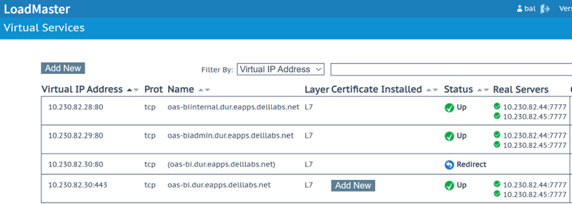 Figure 6. Example Virtual Server Names (called Virtual Services in VLM) configured in the VLM load balancer
As seen in the Figure 6 above, any user request coming in for the three Virtual Server Names (Name column), the VLM load balancer is configured to forward the request to the two OHS web servers (Real Servers column) on port 7777. The two OHS web servers are also referenced as virtual (web) hosts. The three Virtual Server Names are configured and mapped to their respective IPs (Virtual IP Address column) in the DNS.
The three Virtual Server Names (VSN) are further described as under:
- oas-biinternal.delllabs.net – This VSN is for internal communications between the application tier components only. This service is not exposed externally and hence is configured to route over the HTTP protocol.
- oas-biadmin.delllabs.net – This VSN is for OAS administrators who want to access and manage the application tier components using the Oracle FMW Enterprise Manager and/or the Oracle WLS Administration Console interfaces. This service is not exposed externally and hence is configured to route over the HTTP protocol.
- oas-bi.delllabs.net – This VSN is the primary access point for external users who want to connect and access all the OAS product features, including the visualization and analyses. For security purposes, the VLM load balancer is configured to allow access to this VSN only over SSL. Hence, external users need to access this VSN using the secure HTTPS link: https://oas-bi.delllabs.net. Any attempts to access this VSN over the insecure HTTP protocol is configured in the VLM load balancer to get automatically redirected to the secure HTTPS VSN link (row 3 in Figure 6 above).
OHS network configuration
We configured each of the OHS instances to recognize the requests to specific virtual (web) hosts (that map to the OHS web servers configured in the load balancer virtual services) by adding the <VirtualHost> directives in the OHS configuration files. Rather than adding multiple virtual host definitions to a single httpd.conf file, as recommended by Oracle, we created separate configuration files – oas-bi_vh.conf, oas-biinternal_vh.conf, and oas-biadmin_vh.conf - for each of the three Virtual Server Names. And, within each configuration file we defined a set of specific URLs (or context strings) that route requests from the virtual services defined in the VLM load balancer à to the OHS (virtual host) instances à to the appropriate BI component (OAS visualization, analyses, and more) or BI administration (WLS Admin Console or FMW EM) in the WLS and/or the BI domain (in the application tier).
For details on setting up the Oracle HTTP Server in the OAS enterprise solution, refer to the section Configuring Oracle HTTP Server for an Enterprise Deployment.
Application tier network configuration
Whole Server Migration (WSM) network configuration
The Oracle WLS migration framework supports Whole Server Migration (WSM) and Service Migration. So, the design goals in configuring the OAS-BI host network in the application tier was to implement the automatic WSM feature that is supported by the OAS enterprise topology. Additionally, the design goals also included the configuration of the OAS-BI host network to facilitate the manual migration of the Admin Server.
Note: OAS enterprise topology does not support the Service Migration feature.
With WSM configured, if there is a scenario where an OAS-BI host (example OAS-BIHOST1) that is part of the BI Cluster Domain fails then the Managed Server (with all its services and components) running on that failed host is automatically migrated or restarted on any of the other OAS-BI hosts’ machine (example OAS-BIHOST2 machine). So, for the automatic migration of the Managed Server to work using the WSM feature, the OAS-BI hosts should be configured with a floating IP or a virtual IP (VIP) and a corresponding Virtual Host Name (VHN) as the listen address that is mapped to this VIP in DNS.
In case a failure occurs on an OAS-BI host where the Admin Server is actively running (example OAS-BIHOST1) then the Admin Server can be brought up manually on any of the other OAS-BI hosts (example OAS-BIHOST2). For Administration Server failure to work manually, the OAS-BI hosts should also be configured with another VIP and a corresponding VHN as the listen address that is mapped to this VIP in DNS.
Figure 7 shows an example of the network interface configuration on OAS-BIHOST1 that is configured with VIPs for the manual Administration Server migration and the automatic Managed Server migration to work.
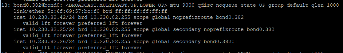
Figure 7. Example of network configuration on OAS-BIHOST1 that is configured with VIPs for the Administration Server and Managed Server migration
Table 3 further elaborates and describes the different OAS-BIHOST1 IP configuration displayed in Figure 7.
Table 3. Example network configuration on OAS-BIHOST1 required for Admin Server and Managed Server migration (Whole Server Migration)
OAS-BIHOST1 IP (interface name)
IP Type
(V)IP Used For…
Example associated (Virtual) Host Name* (mapped in DNS)
10.230.82.42 (bond0.382)
Primary IP
(primary interface name)OAS-BIHOST1 machine
OAS-BIHOST1.delllabs.net
10.230.82.25 (bond0.382)
Secondary IP (VIP) (sub-interface name)
Manual Admin Server migration
OAS-ADMINVHN.delllabs.net
10.230.82.26
(bond0.382:1)
Secondary IP (VIP) (sub interface name)
Auto Managed Server migration (WSM)
OAS-BIHOST1VHN.delllabs.net
Similarly, Table 4 provides the example network configuration on OAS-BIHOST2 that is configured for automatic Managed Server migration using the WSM feature.
Table 4. Example network configuration on OAS-BIHOST2 required for Admin Server and Managed Server migration (Whole Server Migration)
OAS-BIHOST2 IP (interface name)
IP Type
(V)IP Used…
Example associated (Virtual) Host Name* (mapped in DNS)
10.230.82.43 (bond0.382)
Primary IP
(primary interface name)For OAS-BIHOST2 machine
OAS-BIHOST2.delllabs.net
10.230.82.27
(bond0.382:1)
Secondary IP (VIP) (sub interface name)
For auto Managed Server migration (WSM)
OAS-BIHOST2VHN.delllabs.net
Note: In Table 3 and Table 4 the (example) virtual host names listed in column 4 are also used as the listen addresses of their respective Node Managers
Note: Unlike the Managed Servers in the domain, the Administration (Admin) Server uses an active-passive HA configuration. This is because only one Admin Server can be running within a BI cluster domain. Hence, in Table 4 above we do not see the Admin Server VIP configured in OAS-BIHOST2.
WSM also requires configuration of shared persistent storage for Java Messaging Service (JMS), Java Transaction Logs (TLogs), and Database Leasing. This is further described in Persistent stores for JMS, TLOGs, and DB leasing.
Configuring firewalls and ports
For maximum security, it is recommended to configure the firewalls and open only those ports that are required for accessing, operating, and managing the OAS platform and its features. For details of the required ports and protocols that have to be enabled in the different firewall protection zones, see Configuring the Firewalls and Ports for an Enterprise Deployment.