
Dell Technologies 5G Core Validated Design with Oracle and VMware Reference Architecture Guide
Physical network design
Physical network design
-
The following figure shows the distribution of physical components and cabling in the network design:
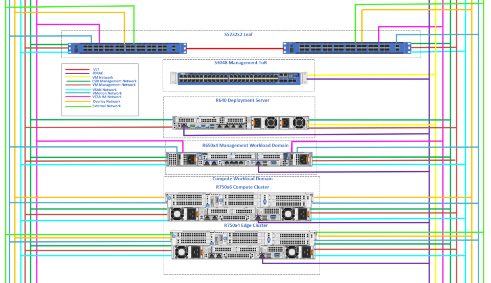
Figure 1. Network connectivity
One stamp (cluster of servers) depicts our 5G Core installation. The stamp hosts:
- Two PowerSwitch S5232F-ON leaf switches. The leaf switches provide connectivity between the endpoints and the data center. Leaf switches are configured as a Virtual Link Trunking (VLT) pair that enables all connections to be active while providing fault tolerance.
- Four servers dedicated to a VMware management workload domain that is running on PowerEdge R650 servers. All the VMware management functions, including Telco Cloud Automation and Harbor, will be running on this cluster.
- Six servers forming a VMware compute cluster and running on PowerEdge R750 servers. All Oracle NFs will run on this cluster.
- Four PowerEdge R750 servers dedicated for an edge cluster.
- One PowerSwitchS3048-ON switch for out-of-band (OOB) connectivity of all iDRAC server ports.
- One PowerEdge R640 server for deployment. This server is used to deploy the solution from a single point that connects to the OOB network. This point is accessible from the corporate network and the in-band network (the management network and leaf switches). The server has a Windows virtual machine (VM) that provides Remote Desktop Protocol (RDP) access to the management workload domain and compute cluster.