
The SFS environment is a self-contained fabric and can be integrated with an existing environment by deploying uplinks from either the spine or leaf switches. For this implementation, only a pair of leaf switches is used. The following uplink characteristics are deployed:
- Dynamic LAGs using LACP
- 4 x 10GE single LAG
The switch ports used for uplinks are configured as a single 100GE port by default. This port (1/1/56) need to be configured as 4 x 10GE. We do this using the SFS UI. Follow these steps to configure the switch ports using the SFS UI:
- Click Switches.
Figure 18. Accessing the embedded SFS UI 
- Click on the > icon to expand the switch ports.
- Click Breakout Ports & Jump Port to access port 1/1/56, which belongs to port-group1/1/8. Click on the > icon in the bottom right-hand corner to move to the next port-group list.
Figure 19. Main SFS UI landing page 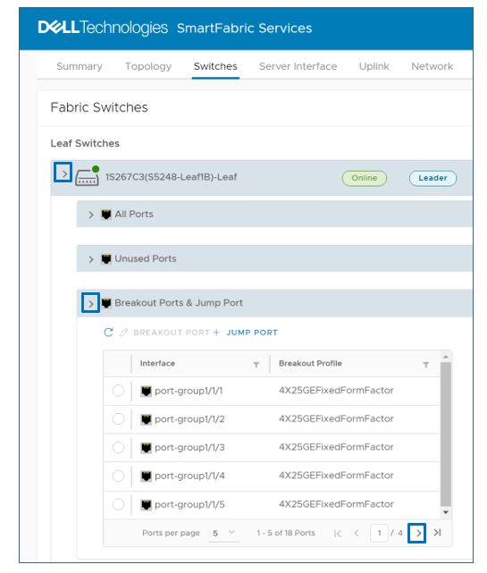
- Click port-group 1/1/8.
- Click BREAKOUT PORT to breakout 1/1/56.
Figure 20. Main SFS UI landing page 
- Click Select Breakout Mode.
- Click 4x10GE.
- Click SUBMIT.
Figure 21. Main SFS UI landing page 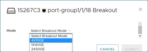
- Click Uplink to deploy the uplink LAG towards the aggregation switches upstream. This will connect the SFS environment onto an existing environment if needed.
- Click CREATE.
Figure 22. Main SFS UI landing page 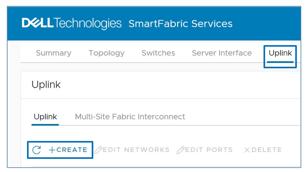
- Click L2 as the uplink type. There are two types of uplinks, Layer 2 and Layer 3. We will deploy a Layer 2 uplink.
- Configure a descriptive uplink name (mandatory) and a description (optional).
Figure 23. Main SFS UI landing page 
- Select the interfaces from each switch that will make up the LAG. In this case, 1/1/56:1-4 from each switch.
- Click LACP as the type of LAG. There are two methods of establishing a LAG, dynamic (LACP) or static. In this case we are using dynamic. This option must match on both ends (downstream and upstream).
- Click Next.
Figure 24. Main SFS UI landing page 
- Add the networks on this uplink. We will add tagged networks (102,214, and 240).
- Click Yes if the environment has vCenter deployed and newly created networks by vCenter need to be allowed on the uplink(s). Otherwise click No.
- Click Finish.
Figure 25. Main SFS UI landing page 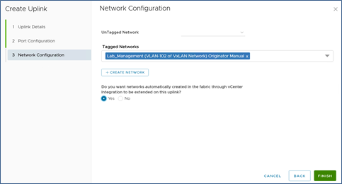
- After the uplink and networks have been deployed, a success message will appear.
Figure 26. Main SFS UI landing page 
This completes the SmartFabric Services deployment.