
The reference architecture used in this implementation requires five networks. The following table shows the networks:
| Network | VLAN ID |
| Infrastructure Management | 102 |
| VDI Management | 214 |
| VDI Compute | 240 |
| NVMe_TCP_A | 30 |
| NVMe_TCP_B | 31 |
Follow these steps to create the networks on the switches using the embedded SFS UI:
- Access the SFS UI (See Accessing SmartFabric Services User Interface UI )
- Click Network
- Click General Purpose Networks
- Click +Create
Figure 9. SFS UI networks deployment 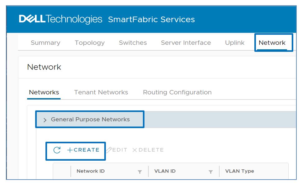
- Enter the network configuration such as the ID, Name, and VLAN_ID
- Click Create
Figure 10. Creating networks 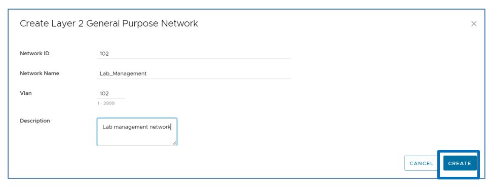
- Repeat Steps 1 to 6 to create the other four networks
Once all of the networks have been created, you should see the following screen showing the networks:
