
PowerFlex software-defined storage
PowerFlex software-defined storage
-
PowerFlex systems combine Dell EMC PowerEdge server hardware with the PowerFlex operating system (PowerFlex software) to create a software-defined SAN. PowerFlex systems are delivered as either a PowerFlex appliance or as a PowerFlex rack system. Both options are fully supported and can be configured to meet a wide range of customer specifications.
Customer configuration options can include high-capacity hard drives, solid-state drives (SSDs), and newer storage technologies such as Non-Volatile Memory Express (NVMe) or Peripheral Component Interconnect Express (PCIe) flash. With these options, customers can create storage tiers that match their capacity and performance requirements. Customers can also use Quality of Service (QoS) settings to define maximum IOPS, maximum IOPS per GB, maximum bandwidth, and maximum bandwidth per GB.
PowerFlex software also supports data compression, which saves valuable storage space on low-latency SSDs. Compression can be configured when a volume is created but is not enabled by default. PowerFlex thin provisioning is a feature that reserves storage space by allocating physical space that is used, enabling more efficient use of storage. Volumes not using compression are thin provisioned by default.
PowerFlex Manager automates and simplifies management of the PowerFlex system including firmware, BIOS, and overall health for both node and switch hardware. PowerFlex Manager checks for compliance with a Release Certification Matrix provided by Dell to ensure proper deployment of a known good configuration. The dashboard also provides a health and history summary of the PowerFlex integrated system. From the dashboard, an administrator can easily monitor server, storage, and services utilization. The resources screen provides a view into PowerFlex nodes, PowerFlex operating system gateways, and hypervisor clusters. For a quick video overview, see Exploring Dell PowerFlex Manager.
With PowerFlex systems, organizations deploying Oracle Big Data SQL can scale from four nodes up to thousands of nodes. This range of scalability provides more granular sizing so that IT departments can start small, with a minimal investment, adding nodes and racks over time. Each additional node adds more capacity and performance.
For our solution, we deployed a PowerFlex rack including PowerFlex nodes in a cabinet with smart power delivery units and thermal sensors. The PowerFlex rack also comes with a white-glove deployment service that ensures a turnkey experience. It also supports bare-metal deployments after securing a support preapproval.
The PowerFlex rack in our lab used Dell EMC PowerFlex R840 nodes for the storage pool. The Storage Data Server (SDS) is a service that runs on each server and is the broker for storage services, as shown in the following figure:
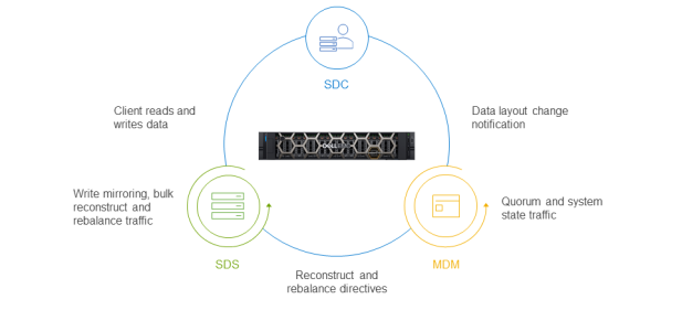
Figure 1. PowerFlex services communication
For this test, the storage architecture used four PowerFlex storage nodes, each running the SDS service. We considered two flexible deployment options. The first option is a traditional two-layer SAN architecture in which applications use compute resources that are separate from the SAN resources, as shown in the following figure. This deployment option works well for applications that require fully dedicated CPU and memory for optimal performance or that work only in a traditional two-layer architecture. In this Big Data SQL solution, only the Oracle Database and Microsoft SQL Server data sources were deployed on individual dedicated servers using a two-layer SAN architecture.
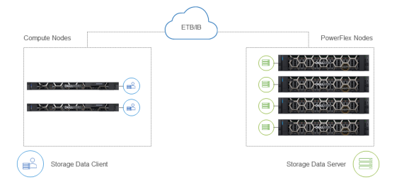
Figure 2. PowerFlex two-layer storage architecture for Oracle and Microsoft SQL Server
The other option is the single-layer deployment option, which is also called a hyperconverged infrastructure (HCI). The single layer option is a model in which compute and storage reside on the same layer, as shown in the following figure. We used this model in our testing for Hadoop and ONDB to maximize consolidation for multiple applications on the PowerFlex nodes by sharing compute resources. The HCI deployment option maximizes a customer’s investment through consolidation.
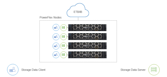
Figure 3. Single-layer (HCI) architecture for Hadoop and Oracle NoSQL
We implemented the PowerFlex HCI architecture using four PowerFlex R840 storage nodes, each running the SDS service. Thus, all four servers contributed to the storage pool for the Big Data SQL solution. The objective of this white paper is to provide best practices for deploying Oracle Bid Data SQL on PowerFlex and performance testing was out of scope in this study.
We configured each PowerFlex R840 node with four Intel Xeon Gold 6240L CPUs featuring 18 cores each. A total of 72 available physical cores (144 logical cores with hyperthreading enabled) were available on each server.
Each server in the HCI configuration had eight 3.84 TB SSDs (a total 30.72 TB of raw capacity) providing a balanced performance and capacity configuration. The following table summarizes the PowerFlex R840 storage component details:
Table 2. PowerFlex R840 component details
Component
Details
Processors
4 x Intel Xeon Gold 6240L CPU @ 2.60 GHz, 18C/36T
Memory
1.5 TB, 24 x 64 GB 2666MT/S
NIC
1 x Intel Ethernet 10G 2P X550/I350 rNDC
NIC
2 x Mellanox ConnectX-4 LX 25 GbE SFP Adapter
Drives
8 x 3.84 GB SAS SSD
The PowerFlex architecture also includes one or more controller nodes that run the Meta Data Manager (MDM) service. The MDM functions as the PowerFlex monitoring and configuration agent that is used mainly for management. A multi-MDM environment consists of one Primary MDM, with other MDMs functioning as tie-breakers. The controller nodes are also responsible for coordinating operations between the client (SDC) and storage data server (SDS). For example, the three controller nodes communicate with clients if the data layout changes, and with the storage nodes for rebalancing activities. The following table shows the component details of the PowerFlex R640 controller.
Table 3. PowerFlex R640 controller component details
Component
Details
Processors
2 x Intel Xeon Gold 6130 CPU @ 2.10 GHz, 18C/36T
Memory
192 GB, 6 x 32 GB 2666MT/S
NIC
1 x Intel Ethernet 10G 2P X550/I350 rNDC
In our tested configuration, the MDM services ran on three PowerEdge R640 controller nodes, as shown in the following figure:
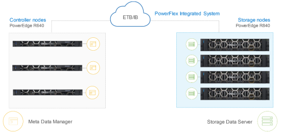
Figure 4. PowerFlex controller nodes
The controller nodes also hosted VMware vCenter for management of virtual machines and the PowerFlex operating system with accompanying gateway services. The PowerFlex integrated rack that we used for testing was designed for high availability (HA). The HA design starts with the RAID 1 mesh mirrored layout, as shown in the following figure:
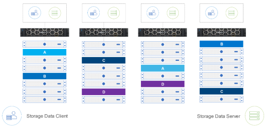
Figure 5. PowerFlex RAID 1 mesh example
With RAID 1 mesh mirrored protection, each data block is stored on two different SDS units ensuring that multiple copies of data reside on separate physical storage. Spreading copies of data across nodes protects against node failure and offers protection against a single drive failure.