
PowerStore best practices
PowerStore best practices
-
For best practices on the storage layer, we had to
- Additional FC ports
Additional FC ports
PowerStore storage arrays use appliances that enable customers to add power, performance, and capacity to an existing array. Each PowerStore appliance has two nodes. These nodes support multiple functions including front-end I/O modules. The front-end I/O modules provide connectivity to the array using various interfaces including Fibre Channel SCSI, Fibre Channel NVMe, iSCSI, and others. In the best practice validation tests, we used only the Fibre Channel interface.
Four PowerStore front-end I/O modules were allocated to each PowerEdge R750 servers. In the baseline configuration, we used one of the total four front-end I/O modules. Figure 2 shows the ports and nodes that we used. The two other front-end modules were reserved for replication. Each front-end module was a 32 Gbps Fibre Channel connection, and the baseline connection consisted of six modules.
In the baseline configuration, we used two of the total four front-end I/O modules per PowerEdge R750 server which limits the paths and the bandwidth available between the PowerEdge servers and the PowerStore storage array.
For this best practice, the two front-end modules were re-zoned and two additional front-end I/O modules were added for each of the PowerEdge servers. We also recreated our Hosts and Host Groups with the updated initiators. This resulted in four paths and bandwidth available for FC connectivity between the PowerEdge hosts and PowerStore Storage.
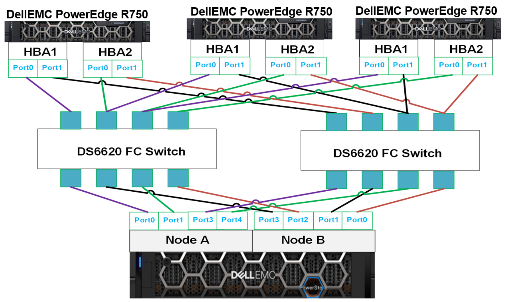
Figure 2. Best practice of maximizing Front-end I/O modules
Recommendation
Each PowerStore appliance and subsequent nodes should be zoned to maximize the FC bandwidth to make the SAN connectivity available. If the ports are not zoned correctly, it can lead to bottlenecks and ultimately performance issues.
Implementation steps
- Add the necessary ports to the FC switches.
- Reconfigure the zoning so the mapping for initiators and targets is implemented appropriately.
- Create new Host Groups on the PowerStore Manager.
- Re-map volumes to new Host Groups.
Contact Dell support for issues related to appropriate reconfiguration.
Additional resources
Dell PowerStore: Microsoft SQL Server Best Practices
Adding storage volumes
Storage configuration can directly influence database performance. This best practice validates the number of storage groups that to further optimize database performance.
Volume groups were allocated to two groups: TarragonDB1 and TarragonDB2. This nomenclature was derived from the program name, Tarragon. All database files for the first of two databases were in the TarragonDB1 volume group. By incrementing the number in the volume group name (TarragonDB<#>), the engineering team created an additional copy of the first database for load tests. This storage configuration minimizes the number of PowerStore volume groups, which eases management but is not an optimized configuration. The following table shows the baseline storage group configuration:
Table 7. Baseline storage group configuration
Volume group
Volume name
VMware volumes
Volume size (TB)
Notes
TarragonDB
TarragonDB1
Tarragon_DB1
1.5
All database files
TarragonDB2
Tarragon_DB2
1.5
All database files
Using multiple volumes for the most active portion of an SQL Server database has many benefits. The primary benefit of using multiple volumes is that the operating system creates an I/O queue path per storage group. The following table shows the optimized PowerStore storage configuration for the SQL Server database.
Table 8. Optimized PowerStore storage group configuration
Volume group
Volume Name
VMware volumes
Volume size (GB)
TarragonDB#
DB#_Data1
DB#_Data1
300
DB#_Data2
DB#_Data2
300
DB#_Data3
DB#_Data3
300
DB#_Data4
DB#_Data4
300
DB#_Log
DB#_Log1
300
TarragonTempDB
TempDB1_Data
TempDB1_Data
300
TempDB1_Log
TempDB2_Log
250
TempDB2_Data
TempDB2_Data
300
TempDB2_Log
TempDB2_Log
250
The goal of generating an optimized configuration was to expand the number of volumes to create more logical I/O paths, resulting in optimized storage performance. The three groups were named: TarragonDB1, TarragonDB2 and TarragonTempDB.
The optimized storage configuration improves the number of I/O paths and other actions like performance monitoring, storage snapshots, and replication. In terms of monitoring storage, the enterprise can view metrics for each part of the database with the optimized configuration. This provides the capability to continually scale capacity and performance as the database grows.
Not all parts of the SQL Server database are required for snapshots. Using this optimized configuration, the database administrator can granularly select what to snapshot, which saves storage capacity. The principle applies to storage replication; the database administrator can select the parts of the database that require protection. By replicating only part of the database, the enterprise benefits from using less network bandwidth.
Recommendation
Implementation steps
To create volumes and volume groups on the PowerStore using the PowerStore Manager, use the instructions provided in the Dell PowerStore Manual.
Creating A VMFS Datastore:
Once storage groups and volumes are created on the PowerStore, create respective VMFS datastores on the vSphere client using the instructions provided in the VMware vSphere product documentation.
When the disks are attached and visible on the operating system, use below steps to partition, format and mount the disks onto the system.
View storage device on RHEL using the following command:
df -h
or
cat /proc/partitions
Once you see your desired storage device listed, use the following commands to create GUID partition table (GPT) on the given storage device.
parted /dev/sdb mklabel gpt -- sdb is a storage device example
Once the partition table is created, use the following command to create volume partitioning. In our case, we will be creating single primary partition with 100% capacity on each storage device.
parted /dev/sdb mkpart primary 2048s 100%
partprobe /dev/sdb
Once partition is created on the storage devices, create the file system (xfs on this case) on the same storage device using the following command:
mkfs.xfs /dev/sdb1
After file system created on the device, we will find the block id and mount on the directory of our choice.
mkdir -p /opt/db/data1  -- data1 is the directory where we will be mounting the volume
mount /dev/sdb1 /opt/db/data1
Make an entry into /etc/fstab to for the mounting to be permanent.
UUID=c4cf7516-c092-4dcd-8366-df58d4f703b2 /opt/db/data1 xfs defaults 0 0
Replace the UUID in above command with one you receive by running the following command.
blkid | grep sdb1
Change ownership of the mounted volume.
chown mssql:mssql /opt/db/data1
Perform all the previous steps on each of the disks attached to the virtual machine.
Additional resources
Dell PowerStore: Microsoft SQL Server Best Practices
VMware vSphere: Adding PVSCSI controllers
Paravirtual SCSI (PVSCSI) controllers offer greater throughput and overall lower CPU use. This best practice tested adding multiple PVSCSI controllers to improve storage performance.
In the baseline configuration, one PVSCSI controller was connect the virtual machine to the PowerStore storage array. Before implementing multiple PVSCSI controllers, the volume group configuration best practiced was implemented. The optimal volume group configuration consisted of adding multiple volumes for data, TempDB data, and TempDB log to create more I/O paths.
The working assumption was using multiple I/O paths and multiple PVSCSI controllers would yield better performance. For this test three additional PVSCSI controllers to each virtual machine for a total of four controllers per virtual machine.
Implementation steps
Implement this best practice at the vCenter user interface. To add PVSCSI controllers, use the following steps:
- From vCenter, select the VM and click Edit Settings > Add Devices > SCSI controller.
- Add three more SCSI controllers, SCSI controller 1 through 3, with these settings:
- Adding PVSCSI controllers to Virtual machine
- Re-map all existing volumes to the new controllers by selecting Edit Settings > Virtual Device Node on each VM.
- Select the appropriate SCSI controller from the dropdown menu. Spread out the volumes across the four controllers as evenly as possible.
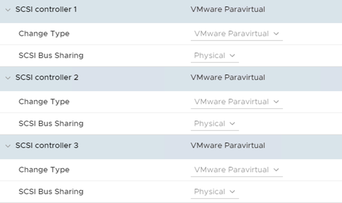
Figure 3. Adding PVSCSI controllers to Virtual machine
Additional resources
Configuring disks to use VMware Paravirtual SCSI (PVSCSI) controllers (1010398)
PowerStore Performance Policy
The PowerStore provides a direct method to manage volume performance relative to one another. It uses a performance policy that sets relative priority to a selected volume. The default performance policy is Medium, which provides equal performance to each volume. For SQL Server workloads, we recommend setting a High performance policy to the data volumes.
Implementation steps
Follow the steps in the PowerStore Manual page to update this property.
Additional resources