
None
None
-
Selecting the appropriate server and network configuration for generative AI inference is crucial to ensure adequate resources are allocated for both management and inference tasks. This section provides example configurations for both management and compute workloads and network architecture.
Management server configuration
PowerEdge R660 head and control plane node
The following table provides the recommended minimum configuration for the management head node and Kubernetes control plan node.
Table 3. PowerEdge R660 head node and Kubernetes control plane configuration
Component
Head node and control plane nodes
Server model
3 x PowerEdge R660
CPU
1 X Intel Xeon Gold 6438M 2.2G, 32C/64T
Memory
8 x 16 GB DDR5 4800 MT/s RDIMM
Operating system
BOSS-N1 controller card + with 2 M.2 960GB (RAID 1)
RAID controller
PERC H755 with rear load Brackets
Storage
4 x 3.84 TB SSD SAS RI 24Gbps 512e 2.5in Hot-Plug, AG Drive 1DWPD
PXE network
Broadcom 5720 Dual Port 1 GbE Optional LOM
PXE/K8S network
NVIDIA ConnectX-6 Lx Dual Port 10/25GbE SFP28, OCP NIC 3.0
K8S/Storage network
1 x NVIDIA ConnectX-6 Lx Dual Port 10/25GbE SFP28 Adapter, PCIe (optional)
Consider the following recommendations:
- For the number of nodes, we recommend three PowerEdge servers for management. NVIDIA Base Command Manager Essentials is installed on one of the servers. If the customer requires high availability, NVIDIA Base Command Manager Essentials can be installed on two nodes as an active-passive cluster. Kubernetes control plane is installed on all three nodes. One node acts as both the NVIDIA Base Command Manager head node and the Kubernetes control plane node. We do not recommend a single-node Kubernetes control plane.
- We recommend the same hardware configuration for all three head nodes for ease of configuration and maintenance.
- Because both the head node and control plane node do not require heavy computing, a single-processor server is sufficient.
- For the head node, we recommend opting for a storage-rich configuration, as this configuration will facilitate convenient storage of images and other essential tools. We recommend four SSD drives. Customers can choose more drives or upgrade to NVMe for better performance.
GPU worker node configuration
Dell Technologies provides a selection of three GPU-optimized servers that are suitable for configuration as worker nodes for Generative AI inference: the PowerEdge R760xa, PowerEdge XE9680, and PowerEdge XE8640 servers. Customers have the flexibility to choose one of these PowerEdge servers based on the specific model size that they require. Larger models, characterized by a greater parameter size, require servers equipped with a higher GPU count and enhanced connectivity. For specific examples of LLM models that can be deployed on each server model, see Chapter 1.
The GPU-optimized servers act as worker nodes in a Kubernetes cluster. The number of servers depends on the number of models and the number of concurrent requests served by those models. We have validated an eight-GPU worker node cluster. The minimum number of worker nodes in the cluster is one.
PowerEdge R760xa GPU worker node
The following table shows a recommended configuration for a PowerEdge R760xa GPU worker node.
Table 4. PowerEdge R760xa GPU worker nodeComponent
Details
Server model
PowerEdge R760xa
CPU
2 x Platinum 8468 2.1G, 48C/96T
Memory
16 x 32 GB DDR5 4800 MT/s RDIMM
Operating system
BOSS-N1 controller card + with 2 M.2 960GB (RAID 1)
Storage
2 x 3.84 TB Data Center NVMe Read Intensive AG Drive U2 Gen4
PXE Network
Broadcom 5720 Dual Port 1 GbE Optional LOM
K8S/Storage Network
- 1 x NVIDIA ConnectX-6 Lx Dual Port 10/25 GbE SFP28, No Crypto, OCP NIC 3.0
- 1 x NVIDIA ConnectX-6 DX Dual Port 100 GbE QSFP56 Network Adapter (Optional)
GPU
Either:
- 2 x or 4 x NVIDIA L40S, 48 GB PCIe GPU
- 2 x or 4 x NVIDIA Hopper H100, 80 GB, PCIe GPU with NVLink Bridge
PowerEdge XE8640 GPU worker node
The following table shows a recommended configuration for a PowerEdge XE8640 GPU worker node.
Table 5. PowerEdge XE8640 GPU worker node
Component
Details
Server model
PowerEdge XE8640
CPU
2 x Intel Xeon Platinum 8468 2.1G, 48 C/96 T, 16 GT/s
Memory
16 x 32 GB RDIMM, 4800MT/s Dual Rank
Operating system
BOSS-N1 controller card + with 2 M.2 960GB (RAID 1)
Storage
2 x 3.84 TB Data Center NVMe Read Intensive AG Drive U2 Gen4
PXE Network
Broadcom 5720 Dual Port 1 GbE Optional LOM
K8S/Storage Network
1 x NVIDIA ConnectX-6 Dual Port 100 GbE QSFP56 Adapter, OCP 3.01 x NVIDIA ConnectX-6 DX Dual Port 100 GbE QSFP56 Network Adapter (Optional)
GPU
4 x NVIDIA H100 SXM
PowerEdge XE9680 GPU worker node
The following table shows a recommended configuration for a PowerEdge XE9680 GPU worker node.
Table 6. PowerEdge XE9680 GPU worker node
Component
Details
Server model
PowerEdge XE9680
CPU
2 x Platinum 8468 2.1G, 48C/96T
Memory
16 x 64 GB RDIMM, 4800 MT/s Dual Rank
Operating system
BOSS-N1 controller card + with 2 M.2 960GB (RAID 1)
Storage
2 x 3.84 TB Data Center NVMe Read Intensive AG Drive U2 Gen4
PXE Network
Broadcom 5720 Dual Port 1 GbE Optional LOM
K8S/Storage Network
2 x NVIDIA ConnectX-6 DX Dual Port 100 GbE QSFP56 Network Adapter (Optional)
GPU
8 x NVIDIA H100 SXM
The CPU memory allocation in the PowerEdge XE9680 GPU worker node configuration exceeds that of the PowerEdge XE8640 configuration. This increase is attributed to the presence of twice as many GPUs that implies a heightened demand for overall inferencing capacity and, therefore, greater CPU memory requirements.
While inferencing tasks primarily rely on GPUs and do not significantly tax the CPU and memory, it is advisable to equip the system with high-performance CPUs and larger memory capacities. This provisioning ensures sufficient allowance for various data processing activities, machine learning operations, monitoring, and logging tasks. Our goal is to guarantee that the servers provide ample CPU and memory resources for these functions, preventing any potential disruptions to the critical inferencing operations run on the GPUs.
Secured Component Verification
Dell Technologies Secured Component Verification (SCV) is a step in the Dell production process that provides assurance of product integrity from the time an order is fulfilled at the Dell factory to end-user delivery. When a client or server product is built, a manifest of installed components is generated, cryptographically signed by a Dell Certificate Authority, and stored securely in the system. When the product is received, customers have a designated SCV validation application, allowing them to verify and validate that no unauthorized system modifications have been made to the components. For more information, see Dell Technologies Secured Component Verification.
Networking design
The following figure shows the network architecture. It shows the network connectivity for compute servers. The figure also shows three PowerEdge head nodes, which incorporate NVIDIA Base Command Manager Essentials and Kubernetes control plane nodes.
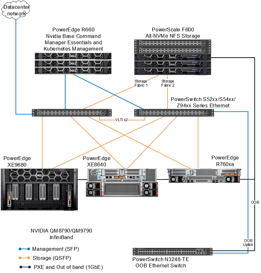
Figure 3. Network architecture
This design requires the following networks to manage the cluster and facilitate communication and coordination between different components and nodes within the cluster:
- Management network—This network is used for communication between the management server and the cluster nodes. It allows the management server to send commands, configurations, and updates to the nodes. It also enables the nodes to report status, resource usage, and other information back to the management server. This network also serves as the Kubernetes network for internode communication in the cluster. It allows the nodes, Kubernetes pods, and services to exchange data, synchronize tasks, and collaborate efficiently during cluster operations.
- External/data center network—The external network connects the cluster to the Internet, allowing the cluster nodes to communicate with external systems, services, and the Internet. This network is essential for accessing external resources, downloading software updates, and interacting with users or applications outside the cluster.
- Storage network—In some configurations, a dedicated storage network might be used to facilitate data transfer between the cluster nodes and storage devices. This network helps to optimize data access and reduce latency for storage operations.
- OOB and PXE network—The out-of-band (OOB) network is a separate and dedicated network infrastructure used for managing and monitoring servers. It is a 1Gb Ethernet network that connects to the Integrated Dell Remote Access Controller (iDRAC) of the PowerEdge servers in the cluster. This network is also used for PXE to automate the provisioning and deployment of operating systems.
Rack design
The following figure shows an example rack design for this design.
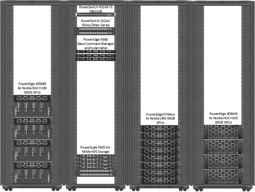
Figure 4. Example rack configuration for Validated Design for Model Customization
This rack was created by using the Dell Enterprise Infrastructure Planning Tool (with the illustrations of the switches enhanced). Filler panels are not shown here. You can use the tool to determine your solution and determine weight, power requirements, airflow, and other details.
This example shows four PowerEdge XE9680 servers in a single rack as well as four PowerEdge XE8640 servers and four PowerEdge R760xa servers in a separate single rack. The four PowerEdge XE9680 servers require four 17kW Power Distribution Units (PDUs). However, you must carefully evaluate your own power and cooling requirements and preference for rack layout, power distribution, airflow management, and cabling design.
If significant growth is anticipated in the size of the deployment, consider separate racks for compute, storage, and management nodes to allow sufficient capacity for that growth.
The following table provides example APC rack and PDU recommendations for the Americas region. Other rack and PDU vendors and options may be used. We recommend that you consult your Dell or APC representative to understand your unique data center requirements to provide an accurate PDU recommendation.
Table 7. Example Example rack and PDU recommendations for the PowerEdge XE9680 server
Servers per cabinet
Rack U height
APC rack model
PDU quantity
APC PDU model
2
42
AR3300
2
APDU10452SW
4
42
AR3350
4
APDU10452SW
2
48
AR3307
2
APDU10450SW
4
48
AR3357
4
APDU10450SW
To understand the critical aspects of deploying a PowerEdge XE9680 server, see the PowerEdge XE9680 Rack Integration technical white paper.