
Design Guide—Data Management with Cloudera Data Platform on Intel-powered Dell EMC Infrastructure
Architecture concepts
Architecture concepts
-
Introduction
Cloudera CDP Private Cloud Base provides data management, enterprise analytics, and management tools for big data. The data management services include HDFS file storage and Ozone object storage. The Cloudera Runtime provides the analytics services, which include components like Hive, HBase, MapReduce, and Spark. The management tools include:
- Cloudera Manager for cluster management, monitoring, and configuration
- Cloudera SDX for security, governance, and metadata
Successful deployment and operation of Cloudera CDP Private Cloud Base depends on a well-designed infrastructure architecture. The architecture must provide high performance, scalability, reliability, and manageability.
Node-level architecture
Node architecture depicts the nodes and services in a CDP Private Cloud Base deployment.
Figure 1. Node architecture 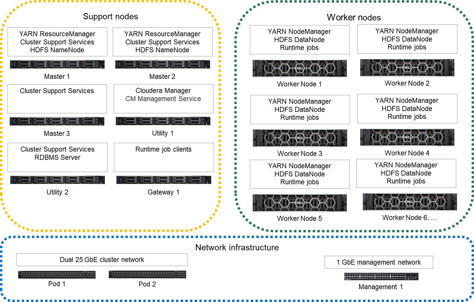
The cluster infrastructure consists of multiple physical server nodes. Each node has a physical configuration that is specialized for its role in the cluster. These nodes are further specialized through the software services that are assigned to them. The table below defines the various cluster nodes and their physical configuration.
Table 3. Node definitions Node Definition Physical configuration Master node This node runs all the services that are required to manage the cluster storage and compute services. Infrastructure node Utility nodes These nodes run Cloudera Manager and other supporting cluster services, such as Cloudera Management Services and supporting databases. Infrastructure node Gateway node This node contains all client-facing configurations and services, including gateway configurations. Infrastructure node Worker node This node runs all the services that are required to store blocks of data on the local hard drives, and run processing tasks against that data. Worker node A high-performance network fabric connects the cluster nodes in a Cluster Data network. An additional Edge network provides an interface between the cluster and external systems and applications. See Network architecture for a detailed description of the network design.
The minimum supported configuration is eight cluster nodes, which include three Master nodes, one Utility node, one Gateway node, and three Worker nodes. Dell Technologies recommends a ten-node cluster with five Worker nodes as a starting point.
Role assignment recommendations
The table below describes recommended host role assignments in a medium-sized high availability deployment.
Table 4. CDP Private Cloud Base nodes and roles Node Service Master node 1 NameNode, JournalNode, FailoverController, YARN ResourceManager, ZooKeeper, JobHistory Server, Spark History Server, Kudu master Master node 2 NameNode, JournalNode, FailoverController, YARN ResourceManager, ZooKeeper, Kudu master Master node 3 JournalNode, ZooKeeper, Kudu master (All require an odd number of masters for high availability.) Utility node 1 Cloudera Manager, Cloudera Management Service, Impala Catalog Server, Impala StateStore, Oozie, Apache Ranger Utility node 2 Hive Metastore, relational database server (such as PostgreSQL) Gateway nodes Hue, HiveServer2, Gateway configuration Worker nodes DataNode, NodeManager, Impala Daemon (impalad), Kudu tablet server These recommendations for role assignments are intended as a starting point. The role assignments may differ depending on the cluster size and the services that are used. See Runtime Cluster Hosts and Role Assignments in the CDP Private Cloud Base documentation for more details.
Node-level architecture with PowerScale storage
An alternative cluster architecture can be used that uses PowerScale OneFS HDFS protocol for storage. PowerScale nodes do not support the Ozone storage protocol. The figure below depicts the nodes and services in this deployment scenario.
Figure 2. Node-level architecture with PowerScale storage 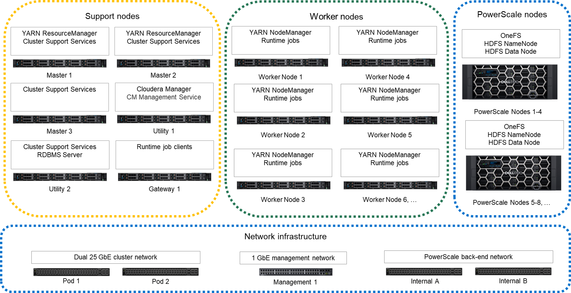
Compute and storage can be scaled independently using this alternative architecture. The PowerScale storage nodes provide the HDFS NameNode and DataNode services instead of the services being assigned to the Master nodes and Worker nodes. The Worker nodes only include enough storage for runtime operations like shuffle-sort spill files and cache.
This alternative architecture reduces the HDFS bandwidth requirements for the Cluster Data network. PowerScale OneFS implements data durability internally and uses a private back-end network for internal operations. A single copy of the data is transferred to the PowerScale storage nodes when Worker nodes write to HDFS. No replication traffic occurs on the Cluster Data network. Also, HDFS recovery traffic for failed drives or nodes does not occur on the Cluster Data network.
High availability
This design implements HA at multiple levels through a combination of hardware redundancy and software support.
- Hadoop storage resiliency
- CDP HDFS implements data resiliency through replication or erasure coding. The HDFS implementation understands node and rack locality, and distributes data to minimize the impact of a node- or rack-level failure.
- HDFS highly available NameNodes
- This design implements high availability for the HDFS directory through a quorum mechanism that replicates critical NameNode data across multiple physical nodes.
- Network resiliency
- The production network uses active load balanced connections to pairs of switches in each pod. Pod-level switches should use redundant connections to switch pairs at the aggregation level. This configuration provides increased bandwidth capacity and allows operation at reduced capacity if a network port, network cable, or switch fails.
- Resource manager high availability
- This design supports high availability for the Hadoop YARN resource manager. Without resource manager HA, a Hadoopresource manager failure causes running jobs to fail. If there is a resource manager failure, jobs can continue running when resource manager HA is enabled.Note: Dell Technologies recommends resource manager HA for production clusters.
- Database server high availability
- This design supports high availability for the operational databases. The database server that is used for the Cloudera Manageroperational and metadata databases stores its data on a RAID 6 or 10 partition. If there is a drive failure, that partition provides storage reliability. Database server high availability can be implemented using:
- One or more additional PostgreSQL instances on other nodes in the cluster
- An external, high availability database server
Note: Dell Technologies recommends implementing HA for the database server.
Cluster sizing and scaling
Cluster sizing and scaling are two different but related considerations. Sizing is concerned with ensuring the cluster meets the workload requirements for storage and processing throughput. Scaling is concerned with growth of the cluster over time as capacity needs increase. Since Cloudera CDP Private Cloud Base is a parallel scale-out system, some sizing requirements can be addressed through scaling while others must be addressed through node level sizing.
Sizing and scaling of a CDP Private Cloud Base cluster are complex topics that require knowledge of the workloads. This section highlights the main considerations that are involved but does not provide detailed recommendations. Your Dell Technologies or authorized partner sales representative can help with detailed sizing calculations.
There are many parameters that are involved in cluster sizing. The primary parameters are:
- Storage capacity
- Storage capacity is usually the first parameter that is used to size a cluster. Calculating storage capacity is important and straightforward. However, storage capacity should be calculated while taking the other sizing parameters into account to maintain a balance between storage and processing capability.
- Data ingest volumes and growth rates
- Data ingest volume and growth rates each have multiple impacts on cluster sizing. Storage capacity should account for growth due to data ingest and growth of ingest volumes. Data ingest also impacts network utilization of the Edge and Cluster Data networks. The network bandwidth that is required for ingest, and the amount of ingest processing required, determine the number of Gateway nodes that the cluster requires.
- Memory and processor capacity
- Memory and processor requirements for jobs running on the cluster must be considered when sizing. Memory and processor capacity increases as nodes are added to the cluster. Workloads like HBase or Spark jobs with large memory requirements may impact sizing of individual nodes in addition to the overall size of the cluster.
- Service level agreements
- Production cluster sizing must meet any performance requirements that SLAs specify. If there are critical path jobs that must meet a specific execution time or throughput, the cluster sizing and balance between compute and storage may have to be adjusted accordingly. Overall cluster throughput is as important as storage capacity, and often influences the number of nodes independent of the required storage capacity.
Cluster scaling
The architecture is organized into three units for scaling as the CDP Private Cloud Base environment grows. From smallest to largest, they are:
- Rack
- Pod
- Cluster
Each unit has specific characteristics and sizing considerations that are documented in this guide. The architecture design enables you to scale the CDP Private Cloud Base environment by adding additional capacity as needed, without replacing any existing components.
Rack
A rack is the smallest size designation for a CDP environment. A rack consists of the power, network cabling, and the data and management switches required to support a group of Worker nodes.
A rack is a physical unit. Physical constraints define its capacity, including available space, power, cooling, and floor loading. A rack should use its own power within the data center, independent from other racks, and should be treated as a fault zone. If a rack level failure occurs in a multiple-rack pod or cluster, the cluster continues to function with reduced capacity.
This architecture uses 12 nodes as the nominal size of a rack, but higher or lower densities are possible. Typically, a rack contains about 12 nodes using scale-out servers like the PowerEdge R660 and PowerEdge R760. Environmental constraints like power and cooling can determine the rack density. The node density of a rack does not affect overall cluster scaling and sizing, but it does affect fault zones in the cluster.
Pod
A pod is the set of nodes that are connected to the first level of network switches in the cluster. It consists of one or more racks. A pod can include a smaller number of nodes initially, and expand over time to a maximum that the available switch ports define.
A pod is a second-level fault zone above the rack level. If a pod level failure occurs in a multiple pod cluster, the cluster continues to function with reduced capacity. A pod can support enough server nodes and network switches for a minimum commercial scale installation.
In this architecture, a pod supports up to 48 nodes (nominally four racks). The recommended pod size is 36 nodes. The size of a pod can vary from this baseline recommendation. Changing the pod size affects the network bandwidth oversubscription at the pod level, the size of the fault zones, and the maximum cluster size.
Cluster
A cluster is a single CDP environment that is attached to a pair of network switches providing an aggregation layer for the entire cluster.
A cluster can range in size from a single pod in a single rack to many pods in multiple racks. A single pod cluster is a special case and can function without an aggregation layer. This scenario is typical for smaller clusters before additional pods are added.
At the cluster level, pod-to-pod (or uplink) network bandwidth factors into overall cluster performance. The maximum oversubscription ratio is of uplink bandwidth 4:1. For most clusters, the oversubscription ratio should be kept close to 2:1. The number of nodes in each pod defines the oversubscription ratio.
Cluster node counts
The minimum supported configuration is eight nodes:
- Three Master nodes
- One Utility node
- One Gateway node
- Three Worker nodes
Although a minimum of one Gateway node is required per cluster, larger clusters and clusters with high ingest volumes or rates may require additional Gateway nodes. Cloudera recommends a baseline of one Gateway node for every 20 Worker nodes.
The recommended cluster node counts are 36 nodes per pod, which results in a 2.25:1 oversubscription ratio and a maximum cluster size of 1152 nodes. Recommended cluster sizing below shows the recommended numbers of nodes per pod and pods per cluster. Those numbers are based on the design that is described in Network architecture. The table also shows some alternatives for cluster sizing with different bandwidth oversubscription ratios.
Table 5. Recommended cluster sizing Nodes per rack Nodes per pod Pods per cluster Nodes per cluster Bandwidth oversubscription 12 36 32 1152 2.25:1 12 48 32 1536 3 :1 12 24 32 768 1.5 :1 12 32 32 1024 2 :1 Cluster storage sizing for HDFS
Total cluster storage capacity is a function of the server platform and disk drives chosen, and scales with the number of Worker nodes. Cloudera supports a maximum of 100 TB per node for HDFS storage.
The amount of usable storage in a cluster also depends on the types of data durability and data compression that are used. The usable storage capacity can be calculated as:
number of nodes x raw storage per node x storage efficiency x compression ratio
This calculation is straightforward but depends on estimating the storage efficiency and compression ratio.
The HDFS storage system supports two options for data durability:
- Replication
- Erasure coding
These options have different storage efficiencies. They also have different performance characteristics, and erasure coding is not supported for all services. For more information, see the Cloudera document, Erasure coding overview.
When replication is used, HDFS creates multiple copies of data across nodes to guard against data loss. The number of replicas (replication factor) is configurable and can be changed on a file-by-file basis. The default replication factor is three, which is the value that is typically used for storage capacity estimates.
HDFS replication decreases the storage efficiency by the replication factor.
When erasure coding is used, data is divided into blocks, encoded with parity, and distributed across nodes. The details of the encoding are specified in an erasure coding policy. Erasure coding policies allow a tradeoff between data durability and storage efficiency. For example, a Reed-Solomon 6-3 policy has durability of 3 and a 67% storage efficiency. A Reed-Solomon 3-2 policy has durability of 2 and a 60% storage efficiency.
HDFS replication and erasure coding can be used simultaneously in a cluster. Erasure coding policies are specified at the HDFS directory level, while replication is specified on a file-by-file basis.
Compression can also be used to reduce the storage required. Compression is optional and applies to individual files. HDFS supports multiple data compression codecs, and it is possible for each compressed file to use a different codec. The compression ratio that is achieved for a given file depends on both the dataset and codec that is used, and is difficult to estimate. The best approach is to:
- Test several different codecs on real datasets to determine what works best.
- Make estimates on the amount of data to be compressed.
Cluster storage sizing for Ozone
The recommended configurations for worker nodes can support HDFS only clusters, or clusters running both HDFS and Ozone storage systems. These configurations are intended to be used during a transition from HDFS to Ozone. The storage in the recommended configurations can be divided between Ozone and HDFS on a drive-by-drive basis. The drives can also be partitioned so each drive supports both storage systems. Partitioning the drives and using logical volumes makes it easier to change the proportion of storage allocated to HDFS and Ozone over time compared to dedicated drives.
Much higher storage density is possible using dedicated Ozone storage nodes. See Ozone hardware requirements for Cloudera's recommendations on role assignment and node sizing for mixed HDFS - Ozone or dedicated Ozone clusters. Ozone architecture provides more detail on the internal implementation of Ozone. Contact your Dell Technologies sales representative for additional assistance sizing and configuring dedicated Ozone storage clusters.
Worker node sizing
Worker node configurations can be optimized for specific workloads.
The recommended configurations are designed to provide a balance of disk and network throughput for general-purpose workloads.
Note: Dell Technologies does not recommend reducing the number of disks in the Worker node. Doing so reduces the available storage bandwidth.Changes to processor and memory size can be made to handle specific workloads. The impact on the overall cluster capacity should also be considered when changing the configurations. See Worker nodes for more details.
Master node sizing
The hardware configurations for the Infrastructure nodes support clusters in the petabyte storage range without changes. You can add more Infrastructure nodes to distribute services across multiple nodes for increased capacity. Adding Infrastructure nodes may be necessary for operational databases or to implement dedicated servers for services like ZooKeeper and Ranger. See Infrastructure nodes for more details about specific server configuration. Use the Cloudera documentation for Runtime Cluster Hosts and Role Assignments to determine the number of utility nodes required and their roles.
PowerScale sizing and scaling
If PowerScale is used for the primary HDFS storage, the sizing and scaling of the cluster is different from implementations using servers with direct attached storage.
The primary difference is that scaling of compute and storage is performed independently by adding either PowerEdge Worker nodes or PowerScale storage nodes. This difference simplifies changing the balance of compute and storage over time. Dell Technologies recommends using the PowerScale H7000. A ratio of five Worker nodes to one PowerScale H7000 storage chassis is a good starting point.
NameNode sizing is also different. When you use PowerScale for primary HDFS storage, the NameNode services are integrated into the PowerScale nodes. Separate NameNode infrastructure servers are not required to be sized and scaled, and the NameNode services are scaled as PowerScale storage nodes are added.
Network bandwidth utilization is different with PowerScale HDFS storage. PowerScale’s data durability replaces HDFS replication and erasure coding when using PowerScale. OneFS implements data durability internally and uses a dedicated backend network. A uniform amount of network bandwidth is used for both reads and writes with PowerScale HDFS because HDFS write replication does not consume additional network bandwidth. This option simplifies cluster throughput calculations and increases performance.
Storage sizing calculation is different since PowerScale determines the translation from raw storage capacity to usable HDFS capacity, rather than HDFS replication and erasure coding.
Some local storage is required on the Worker nodes for intermediate storage when using PowerScale HDFS. This storage is used for MapReduce spill files, Spark cache, and other temporary files. The total intermediate storage across the cluster should be approximately 20% of the total PowerScale HDFS storage. The recommended PowerScale Worker node configurations include this storage. See PowerScale Worker nodes for more information.