
SRDF/Metro Setup
SRDF/Metro Setup
-
This section shows the steps involved in creating SRDF/Metro protection to an Oracle database without the Smart DR component. The section after, Adding SRDF/Metro Smart DR protection to an existing SRDF/Metro, shows the steps of adding Smart DR to an already configured SRDF/Metro. The section after that, Creating SRDF/Metro and Smart DR protection at the same time, shows the steps of creating new SRDF/Metro protection together with Smart DR all at once.
Step 0 – Before we start
Initial Considerations
- Oracle RAC requires a private network utilizing the same subnet across all the nodes, even if remote cluster nodes are in different buildings or data centers. It is essential to have a VLAN (virtual network) in place to support this infrastructure. Since this might be the most challenging part of the configuration it is recommended that this be done first.
- A Witness component is highly recommended in SRDF/Metro setup. The role of a Witness is to be an arbitrator in case the SRDF/Metro ‘local’ and ‘remote’ storage systems cannot communicate. The Witness helps SRDF/Metro determine which is the “winning” side that should continue to service I/Os. The recommendation is to plan for one or more Witnesses.
- SRDF/Metro has an extensive support matrix. It is highly recommended to ensure the environment is supported before starting a deployment.
- There are two possible scenarios for deployment:
- We already have a RAC database on a ‘local’ PowerMax storage system, and we want to turn the configuration into an extended cluster (add cluster nodes).
- The DBAs are waiting for SRDF/Metro to be in place before they can install a new GI and migrate over the database.
- It is expected that each RAC node is zoned and masked to either the local or the remote storage systems, but not both. This increases the solution’s overall simplicity. If using cross-links refer to the section Using cross-links.
- A major consideration is to ensure that both local and remote storage systems have SRDF ports available and zoned to each other over FC or GigE.
Important note: When is the ‘remote’ environment ready for use?
To answer this question, we need to have a closer look at the storage devices in a PowerMax system. Each device has two SCSI identities: an internal identity which is the original WWN and geometry, and an external identity which can be changed to look like another device. SRDF/Metro changes the external SCSI identity of the remote devices to make them identical to the local devices WWNs. This can only happen once SRDF/Metro is fully in sync, and the paired devices’ data is identical, with a replication state of active/active. Only then can ASM use these devices on the remote storage system since now they will be in a RW (Read Write) state.
Note about SRDF naming conventions
In an SRDF environment a minimum of two storage systems are required. SRDF designates the name R1 to the replication source devices and R2 to the replication target devices. Once SRDF/Metro is in active/active state, both sides are equally replicating writes back and forth, so there are no differences between source or target systems, R1 or R2 devices. They are seen as the same device by the host.
When replication stops
If for any reason SRDF/Metro replication stops (planned or unplanned), SRDF will choose a surviving (winning) side, either by the user choice (planned), or by using the Witness rules or Bias rules (unplanned). The devices at the winning side will automatically become or remain R1 devices that are set to RW state and maintain the external SCSI identity used during the active/active replication period. The devices on the side that did not win will become or remain R2, set to WD (Write Disabled state), and their external SCSI identity does not stay the same as it was when they were in the active/active replication period. This is the expected behavior when a cluster is partitioned to avoid any chance of a split-brain situation.
Step 1 – Create an SRDF connection between the storage systems
An initial SRDF group is needed to provide the first path for syscalls[1] to the remote system so that all the other higher functions of our management tools can work in the SRDF environment. Steps to set up the SRDF connection are as follows.
- Select Data Protection-> SRDF Groups-> Click on the 3 dots and select Create SRDF Connection. Then enter local SRDF Group Label, select SRDF Group Number and Local Port.
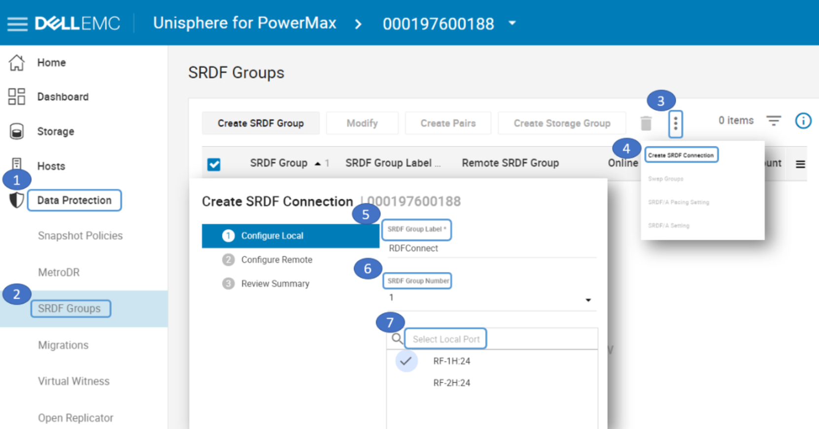
Figure 3. Create SRDF Connection on local side
- Scan and select the Remote Array ID, select Remote SRDF Group Number and Remote Port. Select Review Summary and verify that the SRDF Connection was created.
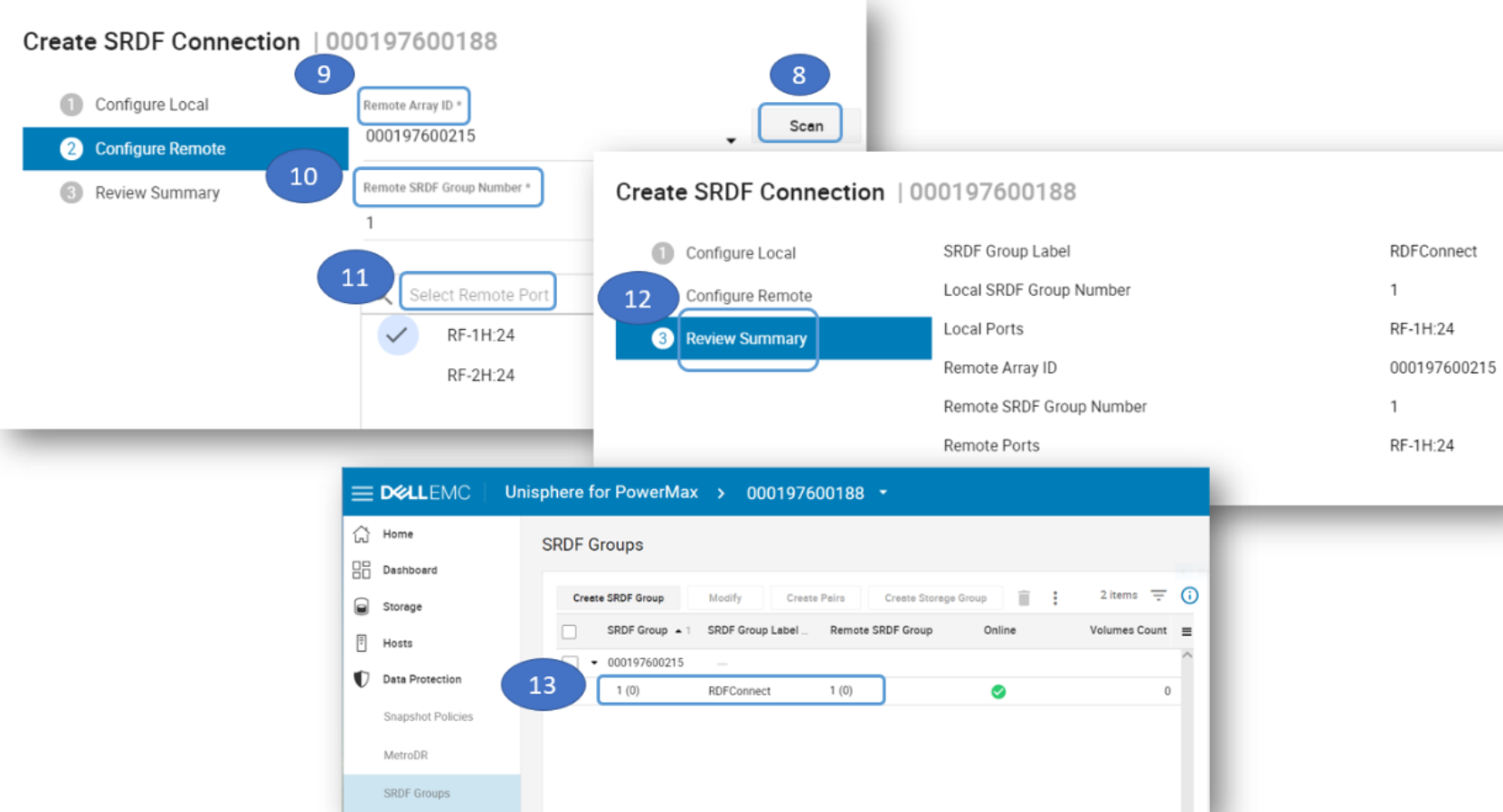
Figure 4. Create SRDF Connection on remote side and verify it was created
Step 2 – Determine which storage groups to protect
A storage group (SG) is a way to group devices together so they can be managed as a single entity. An SG can be stand-alone or in a parent-child relationship. A child SG is just another stand-alone SG. A parent SG contains one or more child SGs. In this way, storage management operations on the stand-alone (or child) SG apply only to that SG, and operations on the parent apply to all its child SGs as a unit. The first step is to determine the SGs to be protected with SRDF/Metro. In the following example grid_sg contains the Oracle +GRID ASM disk group devices (Oracle GI), fra_sg contains the Oracle +FRA ASM disk group devices (archive logs), and db_sg is a parent SG, containing data_sg and redo_sg—Oracle +DATA ASM disk group devices (data files) and Oracle +REDO ASM disk group devices (redo logs).
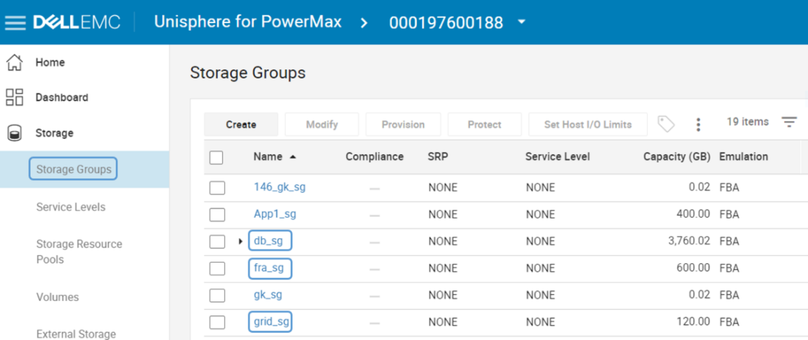
Figure 5. List of SGs to be Protected
Step 3 – Create empty SRDF groups with labels
Create an empty SRDF group with the group label that indicates the SG to be protected. For example, to protect grid_sg, create an empty SRDF group with a Group Label such as “ORACLE_GI”.
Note: the reason we are pre-creating the SRDF group labels and only later selecting them during SRDF/Metro protection step is because when we prepare them in advance, we can select the exact ports we want to use and set the labels to match their proposed usage. Alternatively, it is possible to skip this step and use an ad-hoc SRDF group creation during SRDF/Metro protection step, however, it makes that step more complex.
- Choose Data Protection-> SRDF Groups -> Create SRDF Group. Select Communication Protocol, Remote Array ID, and SRDF Group Label. Select Group Number and Local Ports.
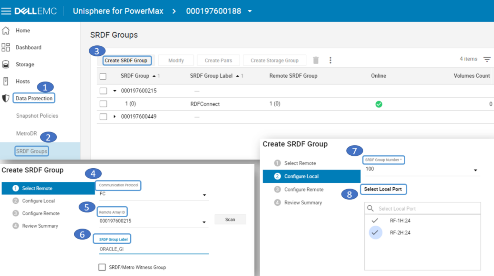
Figure 6. Create empty SRDF Group on local side
- Enter a Remote SRDF Group Number and Remote Ports. Review Summary. Repeat the steps for ORACLE_DB and ORACLE_FRA SRDF groups. Verify group creation.
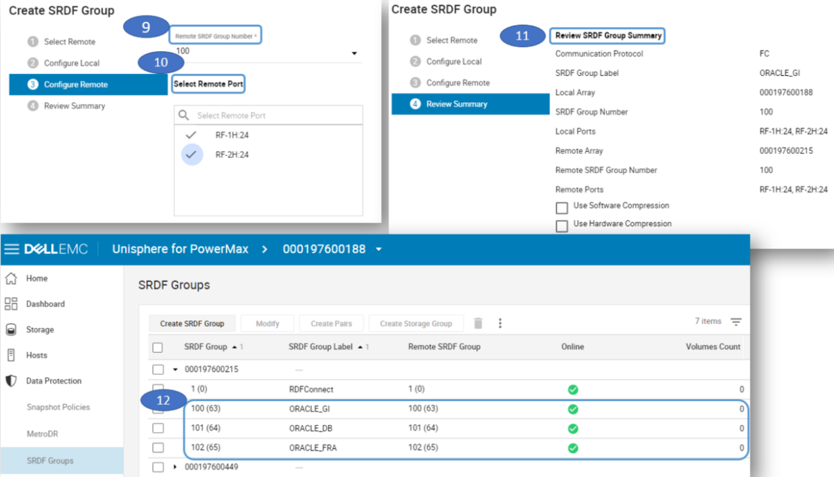
Figure 7. Create empty SRDF Group on remote side and verify creation
Step 4 – Option 1 (not recommended): setup protection using “Bias”
- Select Storage Groups, select the storage group to be protected, then click on Protect. Select Setup high availability using SRDF/Metro.
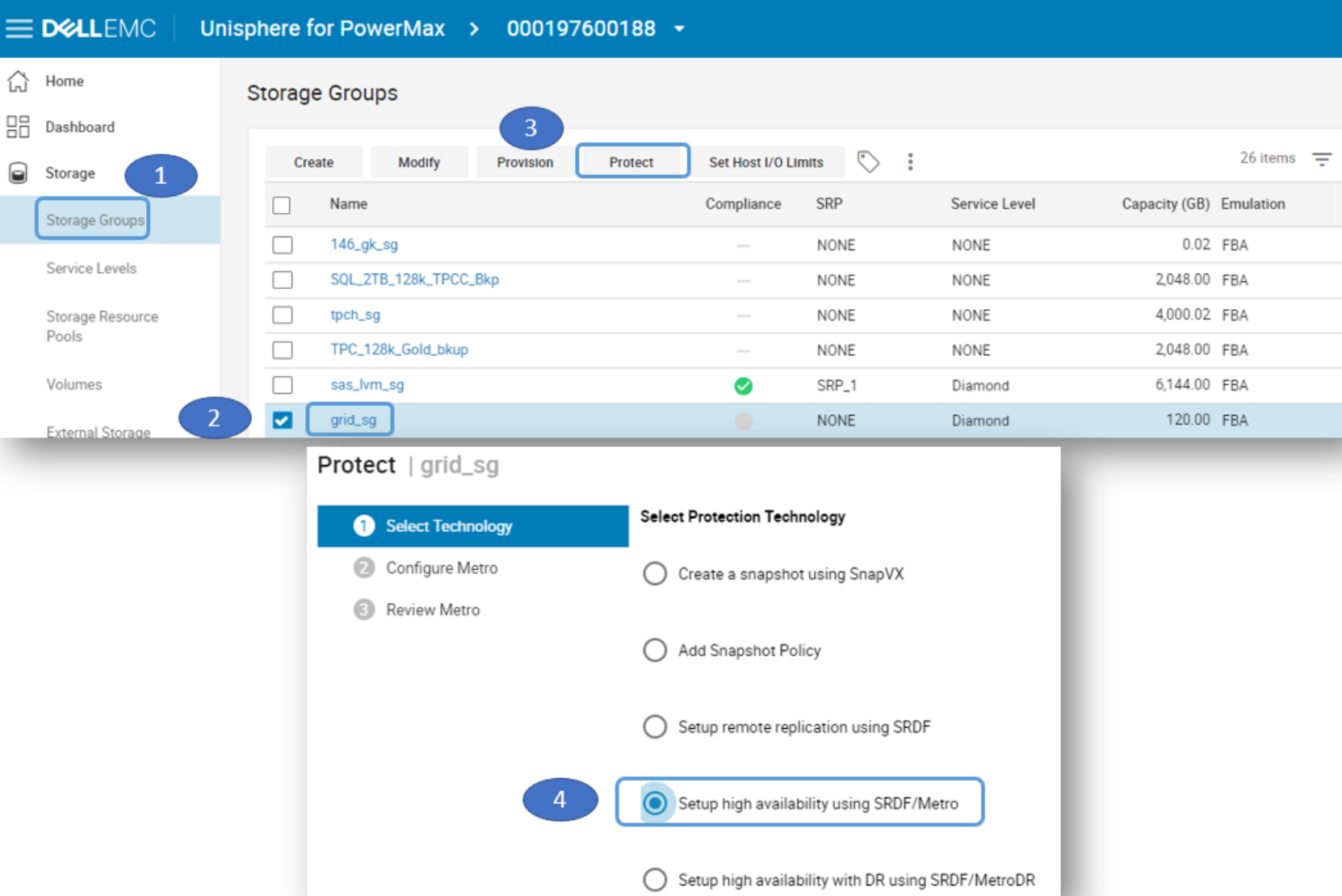
Figure 8. Storage Group selected to protect with SRDF/Metro
- Enter the Remote Array ID, select Manual and click Select. Then select the SRDF Group manually. Select Protected by Bias, enter the Remote Storage Group Name and enter the Remote Service Level for the storage group. Then review the SRDF/Metro summary.
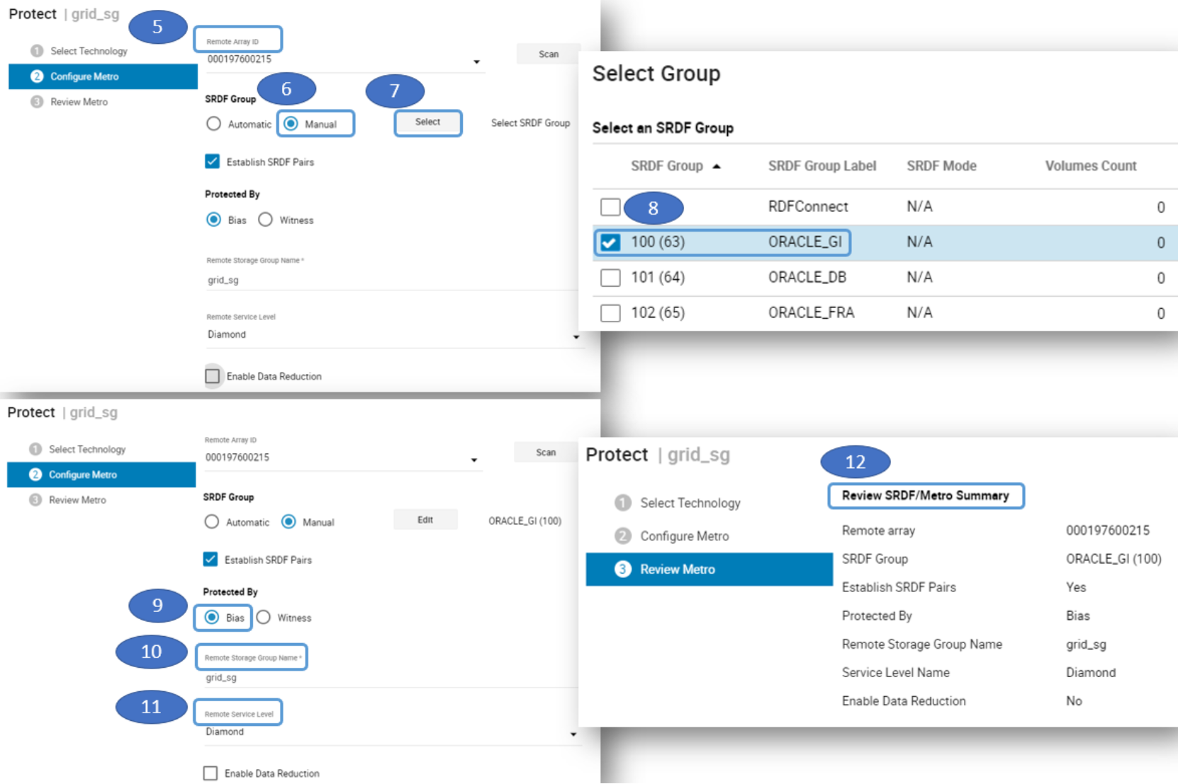
Figure 9. Assigned the “SRDF Group” and “Protected By Bias” using SRDF/Metro
- The storage group grid_sg will be assigned to SRDF Group 100 with Label “ORACLE_GI”. Repeat these steps for the other storage groups to be protected.
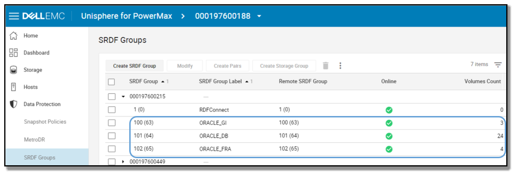
Figure 10. Storage groups Protected By Bias in SRDF/Metro
Step 4 – Option 2 (recommended): setup protection using “Witness”
Although SRDF/Metro can operate without a Witness (using Bias rules), it is highly recommended to configure one or more Witnesses as arbitrators in case of an unplanned cluster partitioning. If the two sides cannot communicate between themselves, the Witness helps SRDF/Metro determine which side to keep alive to avoid a split-brain situation.
There are two choices for Witness configuration: physical or virtual. More than one Witness can be configured, however, only one can be active at a time. In addition, if both physical and virtual Witnesses are configured, the physical takes precedence.
- A physical Witness for SRDF/Metro is simply an SRDF group that doesn’t send any data and merely serves a role of a third site to SRDF/Metro for cluster arbitration purposes only. To create a physical Witness, we create an SRDF group from both the ‘local’ and ‘remote’ storage systems to a third VMAX or PowerMax storage system.
Note: The steps are not shown here, but they are exactly the same as in step 3 where we created an empty SRDF Group, except this time make sure to check the box for “SRDF/Metro Witness Group”. Repeat from both local and remote storage systems.
- A virtual Witness (or vWitness) for SRDF/Metro is simply a pre-configured VMware ESX virtual appliance (vApp) of Solutions Enabler, Unisphere for PowerMax, or Unisphere for VMAX. Adding a virtual Witness is demonstrated below.
- To add a virtual Witness select Data Protection -> Virtual Witness -> Create. Enter a name for the virtual witness. Enter the IP of the virtual witness. Select Add Virtual Witness to remote storage system and enter the storage system ID. The vWitness will be added but not in use.
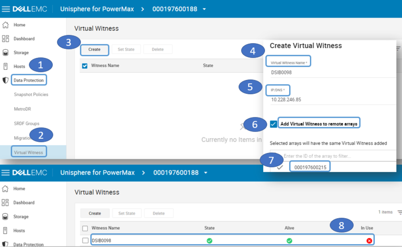
Figure 11. Create the Virtual Witness
- Regardless if physical Witness was added, virtual, or both, now you can protect the storage groups with SRDF/Metro using a Witness. Select the storage group to be protected then click on Protect. Select Setup high availability using SRDF/Metro.
Figure 12. Storage Group selected to protect with SRDF/Metro
- Enter the Remote Array ID, select Manual and click Select. Then select the empty SRDF Group we pre-created manually. Select Protected by Witness, enter the Remote Storage Group Name and enter the Remote Service Level for the storage group. Then review the SRDF/Metro summary.
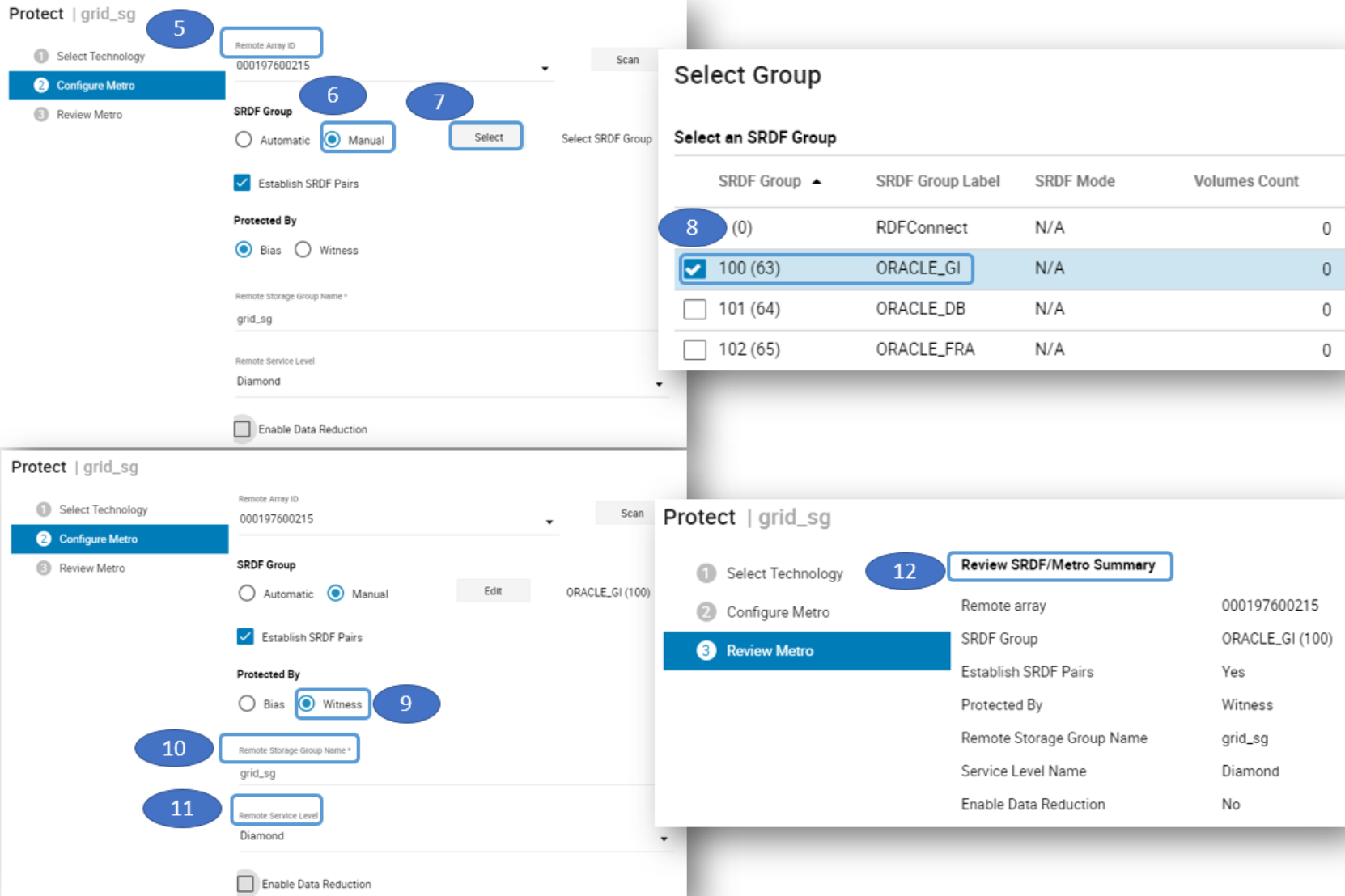
Figure 13. Assigned the “SRDF Group” and “Protected By Witness” using SRDF/Metro
- This figure shows verification that the virtual witness is in use.
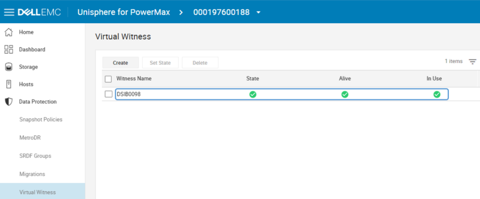
Figure 14. Virtual Witness in use
- The Pair State of the devices will now show Active/Active to indicate that the storage groups are using Witness rules protection.
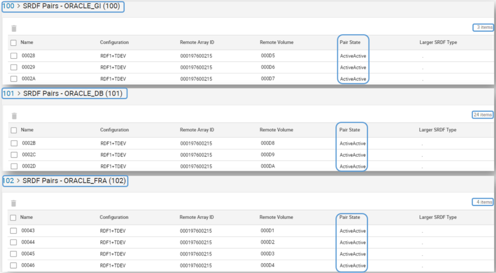
Figure 15. Pair State of devices in Witness rules protection
Step 5 – Masking views creation
PowerMax devices are made visible to hosts through masking views. To create a masking view, you need a storage group (SG), a port group (PG) and an initiator group (IG). The SG contains the devices you want to make visible. The PG contains the storage front-end ports that you want to make the devices visible across. And the IG contains the host bus adaptor (HBA) ports’ WWNs also known as initiators. An IG can be “cascade”, meaning that it can have a parent-child relationship. We recommend that in Oracle clustered environments each database server (cluster node) has its own IG. They can then all be aggregated into the parent IG, representing the cluster. The parent IG is the one used to create the masking view. This allows for easy addition or removal of a node in the cluster by simply adding or removing its IG from the parent IG.
The masking views are stored in the storage system containing the devices. As a result, each server that requires access to devices in a storage system needs to be part of a masking view in that system. Once the masking view is created, the devices in the SG are visible across the storage ports in the PG to the hosts’ initiators in the IG. Any change of a component of the masking view automatically propagates throughout the masking view. For example, if we add devices to the SG, they will automatically be made visible to the servers. If we add or remove a child-IG from parent-IG, the appropriate server will either start seeing or stop seeing devices in the storage group of the masking view.
Two key things to keep in mind when working with masking views
- The masking view does not replace the need for SAN zoning. That means that the physical FC connectivity between host initiators and storage ports, or ‘zoning’, still needs to be taken care of separately.
- Any database server that requires access to newly presented devices will need a reboot or rescan of the SCSI bus to register the new devices when they were made visible for the first time (for example, if using cross links and presenting the remote devices).
Creating masking views
Follow these steps to create masking views:
- Before the masking view is created, the storage admin should create the initiator group (IG) using Hosts -> Hosts menu for each cluster node, then aggregate them into a Host Group or parent-IG for the cluster.
Note: On Linux servers it is easy to identify the initiators’ WWN by running the following command: cat /sys/class/fc_host/host*/port_name. Enter the WWNs of the initiators in Unisphere for each database server.
- Create the port-group (PG) from the Hosts -> Port Groups menu. Once the masking view components are created (IGs, and PG), go to the masking view menu (Hosts -> Masking Views) and create the masking views. Here we created three masking views based on the matching SGs: db_sg, fra_sg, and grid_sg.
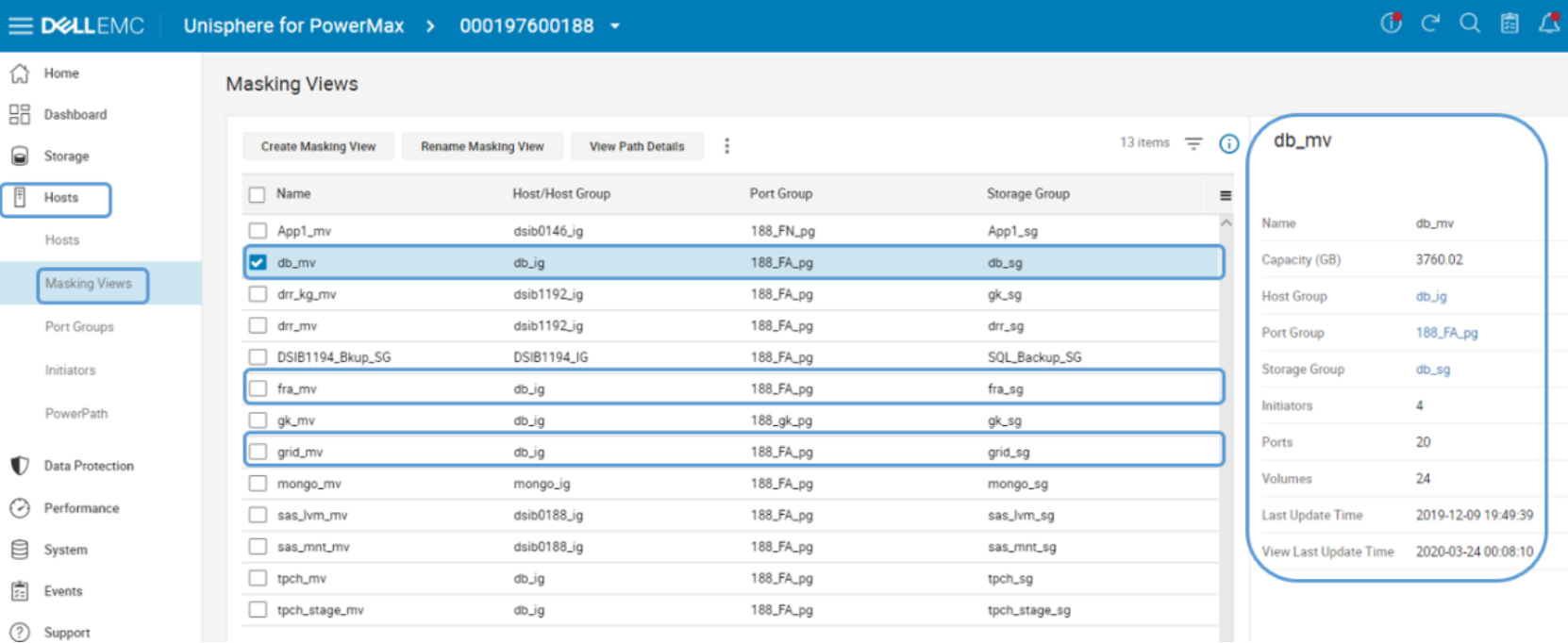
Figure 16. Masking Views created
Note: If cross-links are used then ALL cluster nodes will need visibility to the ‘remote’ devices. If cross-links are not used, then each database server only has visibility to one of the storage systems – the ‘local’ or ‘remote’. In that case, only the servers connected to the ‘remote’ storage system are included in the ‘remote’ storage masking views.
Note: Since masking views are stored in the storage system, if cross-links are used, to create the masking views of the remote storage system, open the remote system’s Unisphere and perform the operation from there.
Using cross-links
Using cross-links increases the overall cluster availability at the cost of added complexity. With cross-links, each cluster node has visibility to the paired devices in both storage systems. For example, if SRDF/Metro replication stops (planned, or unplanned), only one system will “win” and its R1 devices will continue to serve I/Os. The other storage system will turn its devices to R2 and stop servicing I/Os.
Without cross-links, the Oracle instances connected to the storage system with the R2 devices will have to shut down (planned downtime), or crash (unplanned downtime), as no I/Os are allowed and RAC will evict these nodes out of the cluster. However, with cross-links, if the servers survived the “disaster”, ALL cluster nodes will continue to service I/Os from the paths going to the “winning” system’s R1 devices. Perhaps that storage system is further away and reads that previously were serviced from the ‘closer’ system are now a little slower, but all database instances remain up and running, servicing I/Os and users.
Note: Remember that even if cross-links are not used, the database instances connected to the “winning” storage system will continue to service I/Os, and user sessions can automatically reconnect there. Still, some will prefer to not bring down any database instance if possible, even if replication stops or connectivity to one storage system is disrupted.
When using cross-links
- Each cluster node is zoned to both storage systems, and masking views to all nodes are created in both storage systems. As a result, each cluster node has visibility to both local and remote devices.
- In order for both reads and writes to be serviced from the local storage system, if PowerPath is used, enable the auto-standby feature. To do so, run the following command on each database server.

Figure 17. Setting auto-standby feature on
PowerPath uses the response time threshold of each path to determine which are the local and which are the remote paths. It then places the remote paths (the paths with the higher latency) in an auto-standby mode, so they are not used. Only if there are no valid paths to the local device left, it will re-enable these paths.
Note: Auto-standby mode gives PowerPath an advantage in SRDF/Metro configuration with cross-links, as compared to native multipathing. Only the local paths (with lower latency) will service I/Os and the remote paths over the cross-links will be available just in case all the local paths failed.