
Step 7: Masking views creation
Step 7: Masking views creation
-
PowerMax devices are made visible to hosts through masking views. To create a masking view, you need a storage group (SG), a port group (PG), and an initiator group (IG). The SG contains the devices that you want to make visible to the host. The PG contains the storage front-end ports that you want to make the devices visible across. And the IG contains the host bus adaptor (HBA) ports’ WWNs (also known as initiators.) An IG can be “cascade”, meaning that it can have a parent-child relationship. We recommend that in Windows server failover cluster setup each database server (cluster node) has its own IG. They can then all be aggregated into the parent IG, representing the cluster. The parent IG is used to create the masking view. This allows for easy addition or removal of a node in the cluster by simply adding or removing its IG from the parent IG.
The masking views are stored in the storage system containing the devices. As a result, each server that requires access to devices in a storage system needs to be part of a masking view in that system. Once the masking view is created, the devices in the SG are visible across the storage ports in the PG to the hosts’ initiators in the IG. Any change of a component of the masking view automatically propagates throughout the masking view. For example, if we add devices to the SG, they will automatically be made visible to the servers. If we add or remove a child-IG from its parent-IG, the appropriate server will either start seeing or stop seeing devices in the storage group of the masking view.
There are two key things to keep in mind when working with masking views:
- The masking view does not replace the need for SAN zoning. That means that the physical FC connectivity between host initiators and storage ports, or ‘zoning’, still needs to be taken care of separately.
- Any Windows server that requires access to newly presented devices will need to rescan the device to register the new devices when they were made visible for the first time (for example, if using cross links and presenting the remote devices).
Creating masking views
Follow these steps to create masking views:
- Before the masking view is created, the storage admin should create the initiator group (IG) using the Hosts > Hosts menu for each cluster node, then aggregate them into a Host Group or parent-IG for the cluster.
- Create the port-group (PG) from the Hosts > Port Groups menu. Once the masking view components are created (IGs, and PG), go to the masking view menu (Hosts > Masking Views) and create the masking views. Create one masking view for the entire SQL server database parent storage group containing data and log as its children.
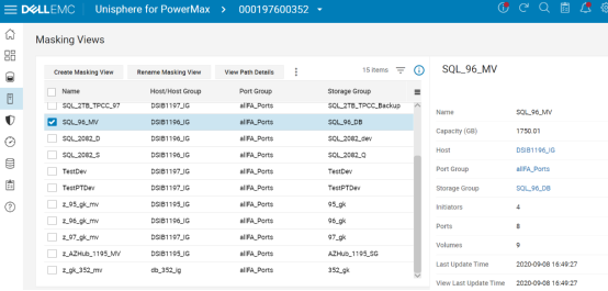
Figure 13. Masking Views created
Note: If cross-links are used then All cluster nodes will need visibility to the ‘remote’ devices. If cross-links are not used, then each database server only has visibility to one of the storage systems – the ‘local’ or ‘remote’. In that case, only the servers connected to the ‘remote’ storage system are included in the ‘remote’ storage masking views.
Note: Since masking views are stored in the storage system, if cross-links are used, to create the masking views of the remote storage system, open the remote system’s Unisphere and perform the operation from there.
Using cross-links
Using cross-links increases the overall cluster availability at the cost of added complexity. With cross-links, each cluster node has visibility to the paired devices in both storage systems. For example, if SRDF/Metro replication stops (under planned or unplanned circumstances), only one system will “win” and its R1 devices will continue to serve I/Os. The other storage system will turn its devices to R2 and stop servicing I/Os.
Without cross-links, the Windows failover cluster nodes connected to the storage system with the R2 devices will have to shut down (during a planned downtime) or crash (in the event of unplanned downtime), because no I/Os are allowed and the failover cluster will evict these nodes out of the cluster. However, with cross-links, if the servers survived the “disaster”, All cluster nodes will continue to service I/Os from the paths going to the “winning” system’s R1 devices. Perhaps that storage system is further away and reads that previously were serviced from the ‘closer’ system are now a little slower, but all database instances remain up and running, servicing I/Os and users.
Note: Remember that even if cross-links are not used, the cluster roles connected to the “winning” storage system will continue to service I/Os, and user sessions can automatically reconnect there. Still, some will prefer to not bring down any cluster roles if possible, even if replication stops or connectivity to one storage system is disrupted.
When using cross-links, adhere to these rules:
- Each cluster node is zoned to both storage systems, and masking views to all nodes are created in both storage systems. As a result, each cluster node has visibility to both local and remote devices.
- In order for both reads and writes to be serviced from the local storage system, if PowerPath is used, enable the auto-standby feature. To do so, run the following command on each database server.

Figure 14. Setting the auto-standby feature to on
PowerPath uses the response time threshold of each path to determine which are the local and which are the remote paths. It then places the remote paths (the paths with the higher latency) in an auto-standby mode, so they are not used. Only if there are no valid paths to the local device left, will it re-enable these paths.
Note: Auto-standby mode gives PowerPath an advantage in SRDF/Metro configuration with cross-links, as compared to native multipathing. Only the local paths (with lower latency) will service I/Os. The remote paths over the cross-links will be available just in case all the local paths failed.