
Solution components
Solution components
-
This solution was released with the latest 3rd Generation Intel Xeon Scalable CPUs, also known as Ice Lake, and the fastest RAM available (3200 MT/s). The following table lists the main components for the solution. Some discrepancies were introduced between the wanted BOM and the actual test hardware because for the pre-release (production level) hardware for our project, only a few CPU models were made available not including the planned life-cycle model.
The At release column lists the components planned to be used at release time and available to customers with the solution. The Test bed column lists the components actually used for characterizing the performance of the solution. The drives listed for data (12 TB NLS) were used for performance characterization, but all supported HDDS and SSDs in the PowerVault ME5 Support Matrix can be used for the solution. Because the ME5 controllers are no longer the first bottleneck of the backend storage, using drives with higher rated speed (10 K, 15 K, and SSDs) might provide some increase in sequential performance. Also, they can provide better Random IOPs and might improve create and remove metadata operations for the standard configuration. For full high-speed network redundancy, two high-speed switches must be used (QM8700 for IB and SN3700 for 100 GbE) and each switch must have one CX6 adapter connected from each server.
Listed software components describe versions used during the initial testing and those used on the released version. However, these software versions might change in between official releases to include important bug fixes, support for new hardware components, or addition of important features.
The following table lists possible data HDDs and SSDs, which is based on the supported drives in the PowerVault ME5 support matrix.
Table 2. Components to be used at release time and in the test bed
Solution component
At release
Test bed
Internal management switch
Dell PowerSwitch N2248X-ON GbE
PowerSwitch S3048-ON
Data storage subsystem
1 x to 4 x PowerVault ME5084 arrays
4 x Dell PowerVault ME5084 arrays
Optional 4 x PowerVault ME484 expansions (One per ME5084 array)
80 – 12 TB 3.5" NL SAS3 HDD drives
Alternative options: 15K RPM:900GB; 10K RPM:1.2TB, 2.4 TB; SSD: 960 GB, 1.92 TB, 3.84 TB; 7.68 TB; NLS: 4 TB, 8 TB, 12 TB, 16 TB, 20 TB
8 LUNs, linear 8+2 RAID 6, chunk size 512 KiB.
4 – 1.92 TB (or 3.84 TB or 7.68 TB) SAS3 SSDs per ME5084 array for metadata – 2 x RAID 1 (or 4 - Global HDD spares, if optional HDMD is used)
4 SSD for metadata or 4 spares
4 global spares
Optional HDMD storage subsystem
One or more pairs of NVMe tier
RAID storage controllers
Duplex 12 Gbps SAS
Capacity without expansion (with 12 TB HDDs)
Raw: 4032 TB (3667 TiB or 3.58 PiB)
Formatted: approximately 3072 GB (2794 TiB or 2.73 PiB)
Capacity with expansion
(12 TB HDDs)
Raw: 8064 TB (7334 TiB or 7.16 PiB)
Formatted: approximately 6144 GB (5588 TiB or 5.46 PiB)
Gateway/ngenea
2 x Intel Xeon Gold 6326 2.9 GHz, 16C/32T, 11.2GT/s, 24M Cache, Turbo, HT (185 W) DDR4-3200
2 x Intel Xeon Platinum 8352Y
2.2 GHz, 32C/64T, 11.2GT/s,
48M Cache, Turbo, HT (205 W)
DDR4-3200
Storage node
Management node
2 x Intel Xeon Gold 6330 2 GHz, 28C/56T, 11.2GT/s, 42M Cache, Turbo, HT (185 W) DDR4-2933
R650 NVMe Nodes
2 x Intel Xeon Gold 6354 3.00 GHz, 18C/36T, 11.2GT/s, 39M Cache, Turbo, HT (205 W) DDR4-3200
Optional High Demand Metadata (R650 NVMe)
2 x Intel Xeon Gold 6354 3.00 GHz, 18C/36T, 11.2GT/s, 39M Cache, Turbo, HT (205 W) DDR4-3200
R750 NVMe nodes
2 x Intel Xeon Platinum 8352Y, 2.2 GHz, 32C/64T, 11.2GT/s, 48M Cache, Turbo, HT (205 W) DDR4-3200
R7525 NVMe nodes
2 x AMD EPYC 7302 3.0 GHz, 16C/32T, 128M L3 (155 W)
2 x AMD 7H12 2.6 GHz, 64C/64T 256M L3 (280 W)
Gateway/ngenea
16 x 16 GiB 3200 MT/s RDIMMs (256 GiB)
Storage node
Management node
Operating system
Red Hat Enterprise Linux 8.5
Kernel version
4.18.0-348.23.1.el8_5.x86_64
pixstor software
6.0.3
Spectrum Scale (GPFS)
Spectrum Scale (GPFS) 5.1.3-1
OFED version
Mellanox OFED 5.6-1.0.3.3
High-performance NIC
All: 2 x Dell OEM ConnectX-6 Single Port HDR VPI InfiniBand, Low Profile
Gateway and ngenea nodes: 4 x CX6 VPI adapters, 2 x FS and 2 x external
High-performance switch
Mellanox QM8700 for InfiniBand HDR (200 Gbps)
SN3700 for 100 GbE (or SN4700 for 200 GbE)
Local disks (operating system and analysis/monitoring)
NVMe servers: BOSS-S2 with 2 x M.2 240 GB in RAID 1
Other servers: 3 x 480 GB SSD SAS3 (RAID 1 + HS) for operating system with PERC H345 front RAID controller
Systems management
iDRAC9 Enterprise + Dell OpenManage 10.0.1-4561
High-speed, management networks and SAS connections
Because the Dell Ready Solution for HPC pixstor Storage is sold with deployment services included, a detailed description of cabling for SAS or high-speed networks is beyond the scope of this document. Cabling of the different components to the management switch is also beyond the scope for this document.
Management servers
Use the PowerEdge R650 server with riser configuration 0 that has 3 x16 slots. The following figure shows the slot allocation for the server:
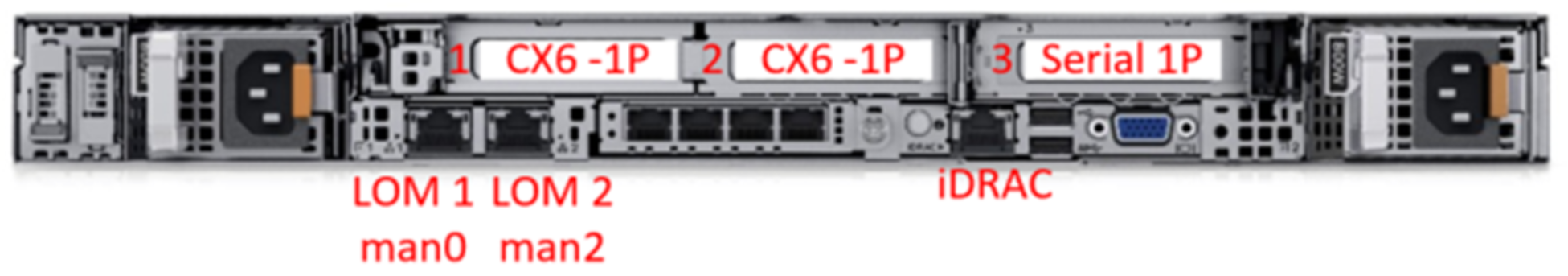
Figure 3. PowerEdge R650 management server - slot allocation
The LAN On Motherboard port 1 (LOM 1), named man0, is connected to the 1 GbE management network. The LOM port 2 (LOM2), named man2, and the iDRAC dedicated port are connected to an external management network to access the pixstor solution. Slots 1 and 2, used for the CX6 adapters, are connected to the high-speed network switches. Slot 3 is used for an optional serial port card.
Storage nodes (SN) servers
Use the PowerEdge R750 server with riser configuration 1 that has eight slots, 2 x6 and 6 x8, as shown in the following figure:
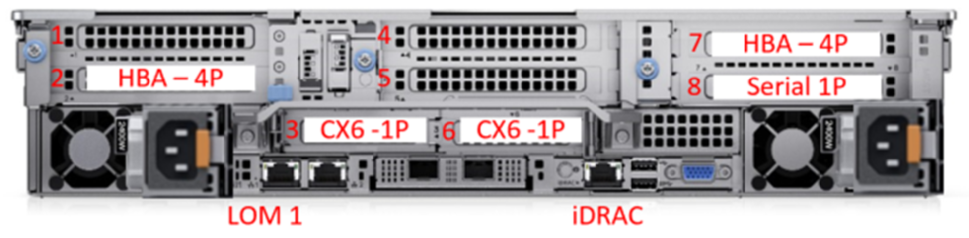
Figure 4. R750 Storage Nodes - slot allocation
The LOM port 1 and iDRAC dedicated port are connected to the 1 GbE management network. All PowerEdge R750 servers use slots 3 and 6 (x16) for CX6 adapters connected to the high-speed network switches. The storage or HDMD servers connected to ME5 arrays have two SAS HBA355e cards in slots 2 and 5 (x8). Slot 8 is used for an optional serial port card.
Backend data storage
For storing data, the solution uses high-density 5U ME5 disk arrays. The following figure shows the controllers of the ME5084 array. One SAS port (A0-A3 and B0-B3) from each controller (A and B) is connected to a different HBA in slots 2 and 7 on each storage node.
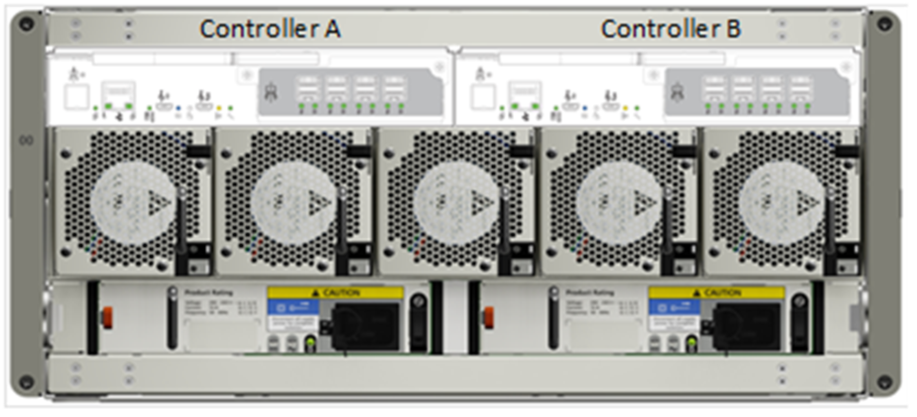
Figure 5. PowerVault ME5084 array - controllers and SAS ports
The SAS connector I/O 0 (the port in the blue box) of each controller is used to connect an I/O Module (IOM) in the ME484 expansion array using port I/O 0 of the corresponding I/O Module (Controller A to I/O Module A, Controller B to I/O Module B).
The following figure shows the back of the ME484 expansion array, where port I/O 0 is the blue SAS port on the left of each IOM.

Figure 6. ME484 expansion - I/O Module and SAS ports
NVMe Nodes
Pairs of the latest PowerEdge servers in HA (failover domains) provide a high-performance flash-based tier for the pixstor solution. The NVMe tier consists of three alternative PowerEdge servers: PowerEdge R650, PowerEdge R750, or PowerEdge R7525. An important difference from previous pixstor releases is that NVMesh is no longer a component of the solution. For HA purposes, an alternative based on GPFS replication of NSDs was implemented across each NVMe server HA pair to functionally have mirrored NSDs.
For PowerEdge R650 servers, each server has 10 NVMe devices directly attached, six to the CPU in Socket #1 and four for the CPU in socket #2 (therefore, this configuration is not a balanced configuration in terms of NUMA domains), and two HCAs Mellanox ConnectX-6 Single Port VPI HDR 200 Gbps adapters (one per CPU socket). Any NVMe device supported on the PowerEdge R650 server is supported for these NVMe nodes. Both CX6 interfaces are used actively to move data, replicate the NVMe NSDs, and provide connectivity from the file system to clients. In addition, they provide hardware redundancy at the adapter, port, and cable level, but performance is affected if only one CX6 adapter is working.
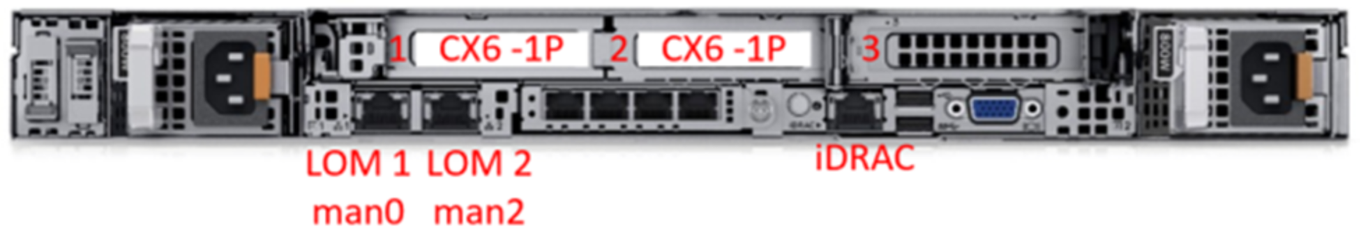
Figure 7. PowerEdge R650 NVMe node slot allocation
For PowerEdge R750s servers, each server has 16 NVMe devices directly attached, eight to each CPU, and two HCAs Mellanox ConnectX-6 Single Port VPI HDR 200 Gbps adapters (one per CPU socket). Therefore, this configuration is a balanced configuration in terms of NUMA domains. Any NVMe device supported on the PowerEdge R750 server is supported for these NVMe nodes. Both CX6 interfaces are used actively to move data, replicate the NVMe NSDs, and provide connectivity from the file system to clients. In addition, they provide hardware redundancy at the adapter, port, and cable level, but performance is affected if only one CX6 adapter is working.
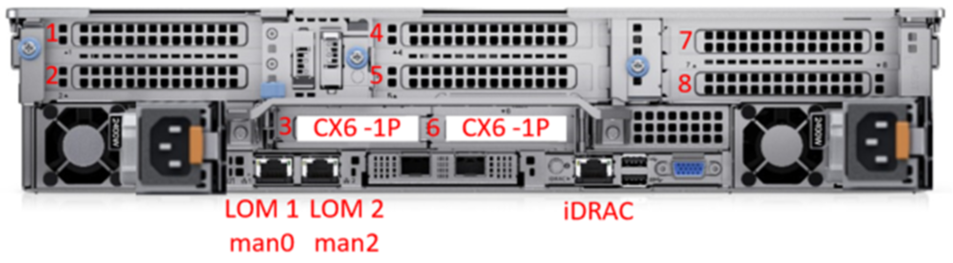
Figure 8. PowerEdge R750 NVMe node slot allocation
For PowerEdge R7525 servers, each server has 24 NVMe devices directly attached, 12 to each CPU, and two HCAs Mellanox ConnectX-6 Single Port VPI HDR 200 Gbps adapters (one per CPU socket). Therefore, this configuration is a balanced configuration in terms of NUMA domains. Any NVMe device supported on the PowerEdge R7525 server is supported for these NVMe nodes. Both CX6 interfaces are used actively to move data, replicate the NVMe NSDs, and provide connectivity from the file system to clients. In addition, they provide hardware redundancy at the adapter, port, and cable level, but performance is affected if only one CX6 adapter is working.
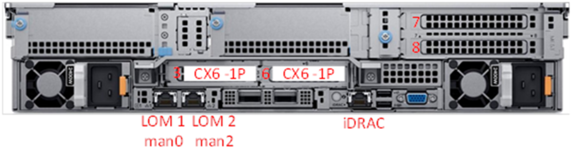
Figure 9. R7525 NVMe node slot allocation
To maintain homogeneous performance across the NVMe nodes and allow proper striping data across nodes in this tier, do not mix different server models in the same NVMe tier. However, multiple NVMe tiers each with different servers and accessed using different filesets is supported.
The selected PowerEdge servers support NVMe PCIe4 and PCIe3 devices. However, mixing NVMe PCIe4 devices with lower performant PCIe3 devices is not recommended for the solution and it is not supported for the same NVMe tier. Additional pairs of NVMe nodes can scale out performance and capacity for this NVMe tier. Selecting the appropriate capacity for the NVMe devices supported on the servers or adding more pairs of servers provides increased capacity.
Gateways/ngenea nodes
Use the PowerEdge R750 servers with riser configuration 2 that has six slots, 2 x8 and 4 x16, as shown in the following figure:
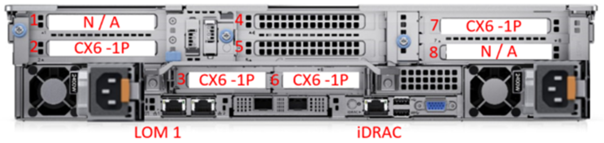
Figure 10. R750 Gateway or ngenea nodes - slot allocation
Management switch
This generation of the solution uses the PowerSwitch N2248X-ON that is used as a simple Layer 2 switch using 1 GbE ports, as shown in the following figure:
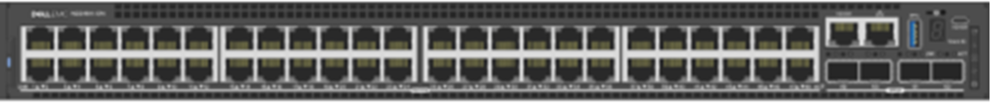
Figure 11. Management Switch - N2248X-ON
High-speed network switch
The solution uses CX6 VPI adapters that can be configured as InfiniBand or Ethernet as needed.
For InfiniBand deployments, a pair of Mellanox QM8700 IB HDR 200 Gbps switches (as shown in the following figure) are required unless the customer HPC cluster has enough free ports for all the redundant connections from the different pixstor servers.

Figure 12. InfiniBand HDR-managed switch – QM8700
For Ethernet deployments, a pair of Mellanox SN3700 Ethernet 200 Gbps switches (shown in the following figure) are required unless the customer HPC cluster has enough free ports for all the redundant connections from the different pixstor servers. There is also a 100 Gbps version of the switch, the SN3700C (not shown).

Figure 13. Ethernet 200 Gbps managed switch – SN3700
Storage configuration on ME5 arrays
The Dell Validated Design for HPC pixstor Storage has two variants: the standard configuration and a configuration that includes the HDMD module.
On the standard configuration, the same pair of PowerEdge R750 servers uses their ME5084 arrays to store data on NLS SAS3 HDDs or SSDs. The following figure shows this ME5084 configuration, showing how the drives are assigned to the different LUNs. Note that each ME5084 array has eight linear RAID 6 (eight data disks + two parity disks) disks groups used for data where only HDDs are selected, alternating even-numbered disk slots for one LUN and odd-numbered disk slots for the next LUN. That pattern repeats until all 80 NLS disks are used. The last four disk slots have SAS3 SSDs, which are configured as two linear RAID 1 pairs, and only hold metadata. Linear RAIDs were chosen over virtual RAIDs to provide maximum performance for each virtual disk group. Similarly, RAID 6 was chosen over ADAPT for performance, despite the speed advantage of the latter when rebuilding after failures.
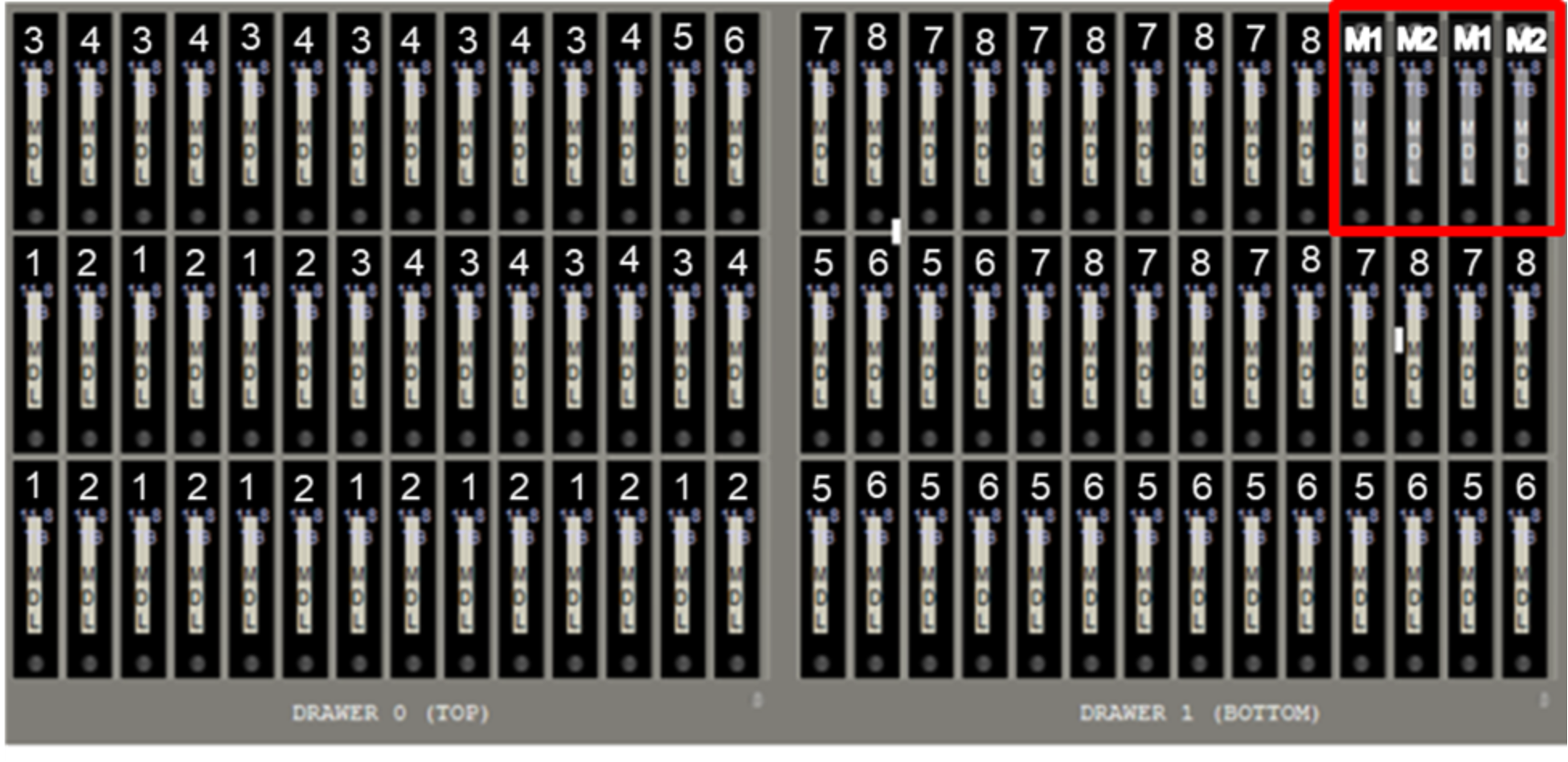
Figure 14. ME5084 (or MD484) drives assigned to LUN for standard configurations
When the storage module has a single ME5084 array, then GPFS is instructed to replicate the first RAID 1 to the second RAID 1 as part of a failure group. However, when the storage module has two or four ME5084 arrays, the arrays are divided in failure group pairs and GPFS is instructed to replicate each RAID 1 from one array to the other array in its failure group. Therefore, each RAID 1 always has a replica managed by a GPFS failure group.
All the virtual disks have associated volumes that span their entire capacity and are mapped to all ports so that they are accessible to any HBA port from the two PowerEdge R750 servers connected to them. Each PowerEdge R750 server has one HBA port connected to each ME5084 controller from the storage arrays. If one server is operational and only a single SAS cable remains connected to each ME5084 array, the solution can still provide access to all data stored in the ME5 arrays. Optional ME484 capacity expansion arrays use the same configuration as the ME5084 arrays to which they are connected, including the four SSDs for metadata.
When the optional HDMD module is used, the eight RAID 6 are assigned like the standard configuration and are used only to store data. However, instead of SSDs, the last four disk slots have NLS SAS3 HDDs to be used as hot global spares for any failed disk in the array, as shown in the following figure:
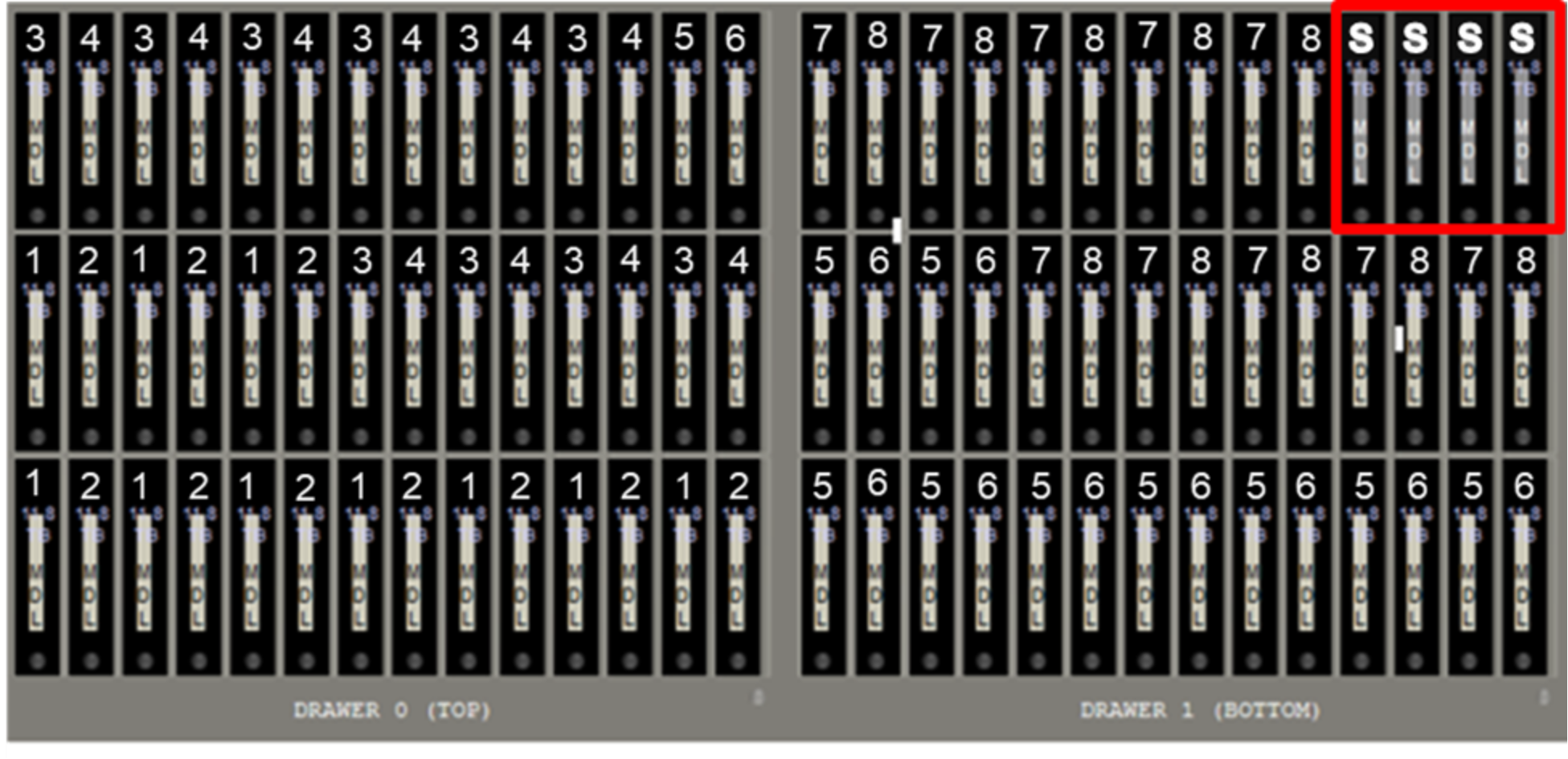
Figure 15. ME5084 (or ME484) drives assigned to LUN for configuration with HDMD
When the optional High Demand Metadata Module is used, optional capacity ME484 expansion arrays used must have the same configuration of the ME5084 array to which they are connected, including the four spare HDDs.
All the disk groups on the storage module are exported as volumes that are accessible to any HBA port from the two PowerEdge R750 servers connected to the corresponding ME5 arrays. Each PowerEdge R750 server has one HBA port connected to each ME5 controller from its storage arrays. If one server is operational and only a single SAS cable remains connected to each ME5 array, the solution can still provide access to all data or metadata stored in those arrays.
Finally, high-speed networks are connected using CX6 adapters to handle information exchange with clients and to determine if a node that is part of a module is operational (for HA purposes).
Administration, advanced analytics, and search
Among pixstor capabilities, monitoring the file system using advanced analytics can be essential to greatly simplify administration, helping to find problems or potential issues proactively or reactively.
Monitoring a solution is essential to keep it working optimally, as is promptly detecting and correcting any problems, even before they cause failures or affect functionality. The following figure shows the solution dashboard, from which an inspection can detect issues affecting the solution health requiring immediate action (critical in the last monitor area), scheduling of an action (service alert), or problematic use trends. The network and disk throughput graphs might help detect situations where the system is not optimally used, and then focus on details to find a cause.

Figure 16. Monitoring dashboard
The following figure shows that only two clients are using network read bandwidth, and a third client is briefly using bandwidth. Disk and disk pool use (third and fourth graphs on the first row) might detect imbalances that can degrade capacity or a trend that over time that might cause the file system to reach its maximum capacity, allowing preventive actions to be taken before production is affected by a file system that becomes full. The solution’s server load, CPUs, and memory use, which have predefined thresholds that alert when the system is facing a load that might degrade performance, can detect more transient problems. The single panel view allows you to investigate problems and the related components to take corrective actions, determine data trends to justify changes in use policy, or help plan for future growth of some or all the solution components to meet evolving demands.
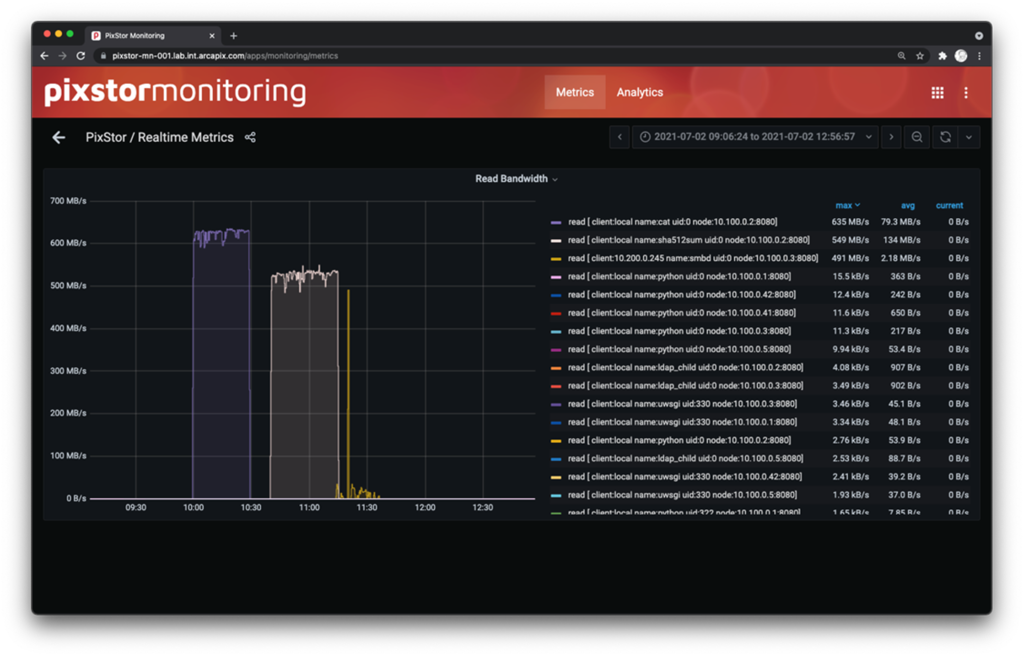
Figure 17. Network Metrics, Read Bandwidth detail
Learning that a file system is at a certain capacity does not help detect some problems that affect productivity. Accessing a large number of small files might cause unexpected peaks in the system load, without showing a sizable increase in used capacity. Certain cyclic transient events might affect the system load and capacity, but after completion, the system returns to the previous state without enough information to understand the situation. In these cases, pixstor analytics can access historic use, retrieve information about capacity used and number of files per file type, or retrieve details by filesets or by projects to help detect the situations previously mentioned.
The following figure shows useful information based on the file system capacity. The left side shows the file system total space used and the top ten users based on file system capacity used. The right side provides a historical view with capacity used across many years, the top ten file types used and top ten filesets, both based on capacity used and in a Pareto chart. With this information, it is easy to determine which users access the file system excessively, identify capacity use trends to decide future growth for capacity, ascertain what files are using most of the space, or ascertain which projects are taking most of the capacity. Not only does this analytics tool provide insight to the capacity use, but also to the number of files (inodes) and to the details of the file sizes that are being populated on the file system. This information offers the opportunity for a customer to make investment decisions on actual file system use information rather than anecdotal reports.

Figure 18. pixstor analytics - Capacity view
Another essential pixstor tool provides advanced search capabilities for administrators and users allowed to access the management servers. On most parallel file systems, extensive searches can negatively affect performance (like the effects of ls -IR <mount_point>/* on a regular parallel file system with many files). However, pixstor search software works independently of the PFS metadata, avoiding negative performance effects, making the searches efficient, and allowing complex searches that are normally difficult to perform on a PFS.
The following figure shows the search results on different folders with an analytics window overlay:
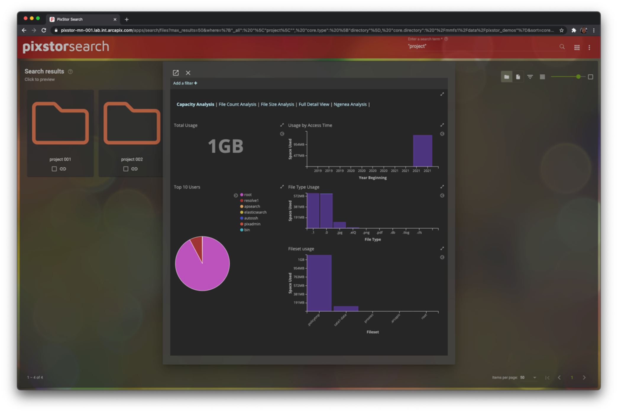
Figure 19. Search showing results by folder with an analytics overlay
Search results can take advantage of previews (for example, for images), which allow more efficient screening of the results than a list of filenames. In addition, pixstor can take advantage of being a multi-tier solution with a single namespace, including other storage solutions connected with ngenea nodes. This characteristic allows datafiles to reside in external storage, while metadata stubs are kept on pixstor, which enables searches to be performed as if it were present locally. If a file is needed but is not local to the pixstor file system, it can be readily moved back.
The following figure shows an example of a pixstor search using previews of medical images, and informing which results were found, but not immediately available for consumption:
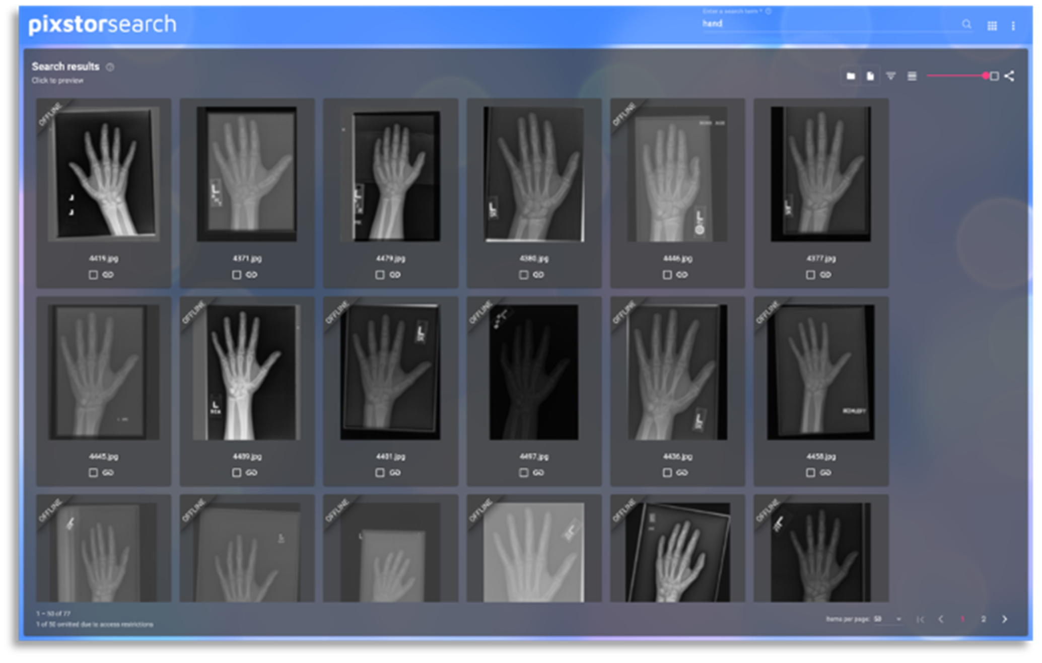
Figure 20. Search results using previews
Gateway nodes
Gateway nodes use the PowerEdge R750 server but with a different RAID configuration that has four x16 slots and two x8 slots available for any other adapter. The four x16 slots have Mellanox ConnectX-6 Single Port VPI adapters that can be configured for either IB HDR or Ethernet 200 Gbps connections, or any of the speeds supported by those adapters. At least one of those adapters must be connected to the pixstor solution for access to the file system or two connections if redundancy is required on any single gateway. In addition, the gateways can be connected to other networks adding NICs supported by the PowerEdge R750 server on the two x8 slots available (one internal x8 slot is used by a special PERC adapter to manage local SSDs for the operating system).
Samba’s Clustered Trivial DataBase (CTDB) is a clustered database used to manage the NFS and SMB services on the gateway nodes, providing high availability, load balancing, and monitoring of the nodes in the CTDB cluster. For each of the gateways in the CTDB cluster, a Domain Name System (DNS) entry with an A record for the IP address is added, such that all gateways have the same hostname, a sort of “public gateway name.” Clients then use that gateway name to mount those services so that the name server daemon (named) can assign all the gateways in the CTDB cluster to clients using the round-robin method. When needed, NFS-Ganesha (an open source, user space NFS file server) can be used as an alternative to the regular NFS server services; it is also managed by the CTDB cluster.
Behind the gateways, a pixstor system must be accessed and exported to the clients. For characterizing the gateways in this document, a pixstor solution with high demand metadata and the capacity expansion modules was used.
Gateway node performance is expected to be similar to GFPS performance reported in this document. Gateway performance characterization will be performed and reported in a future blog.
ngenea nodes
The hardware for ngenea nodes is the same used for the gateway nodes, but has different software installed and requires a different license. These nodes were validated several solutions like a PowerScale F200 (OneFS), a tape solution, and we plan to validate on other Dell storage systems. The following figure shows an example of ngenea jobs using external storage. A future blog will describe this software in more detail and may present some performance characterization / use case relevant for the pixstor Storage.
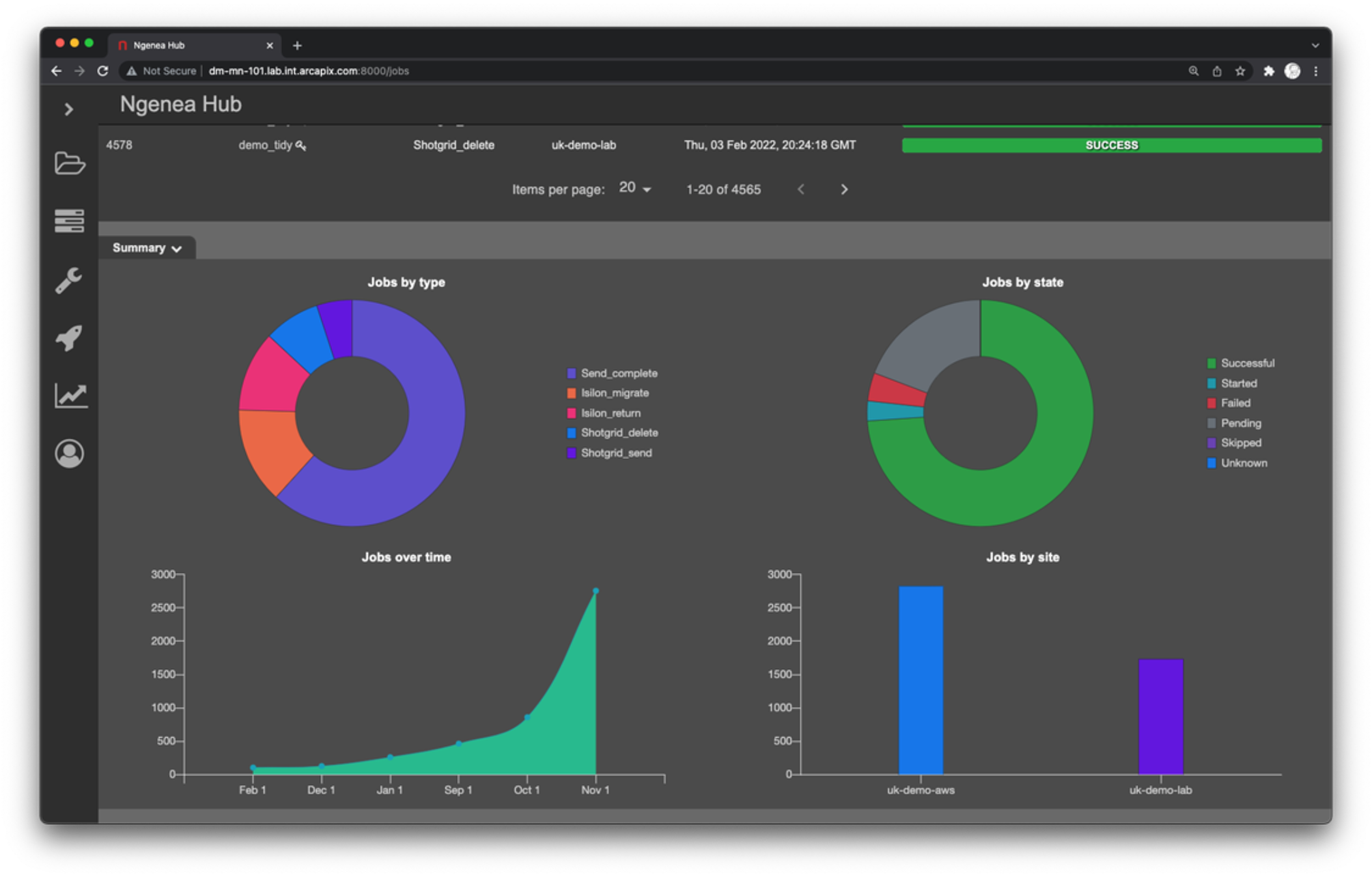
Figure 21. Example of Ngenea Hub showing related jobs