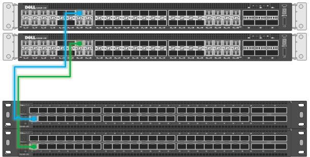
The vSAN surveillance nodes and ECS nodes are not connected internally and must be integrated through external switches. Each node should be connected to 2 physical switches to ensure redundancy and avoid a single point of failure.
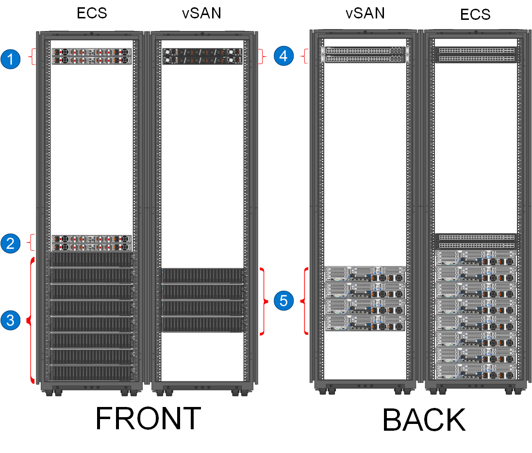
The following figure shows the standard configuration for the ECS and vSAN racks and a basic connection overview for the switches.
- Dell S5248F-ON 25 GbE switches
- Dell S5248F-ON 25 GbE switches
- Dell ECS EX500
- Dell S4148-ON 10 GbE switches
- Dell PowerEdge R740xd2 Ready Nodes
Connecting the vSAN surveillance nodes
Connect the vSAN surveillance nodes to the network starting with ports 47 and 48 on the switch. Add additional surveillance nodes using open ports in descending order (right to left) on the switch, as illustrated in the following figure.
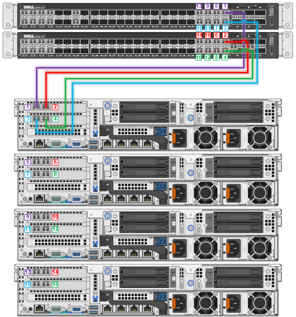
Connecting the ECS
Connect the ECS cabinet to the vSAN through the network switch starting with port 13 on both switches, as illustrated in the following figure. Add additional ECS cabinets using open ports in ascending order (left to right) on the switch starting with port 14.