


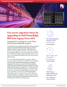
Cut server migration times by upgrading to Dell PowerEdge MX from legacy Cisco UCS
Read the report See the science View the infographicThu, 30 Mar 2023 15:55:57 -0000
|Read Time: 0 minutes
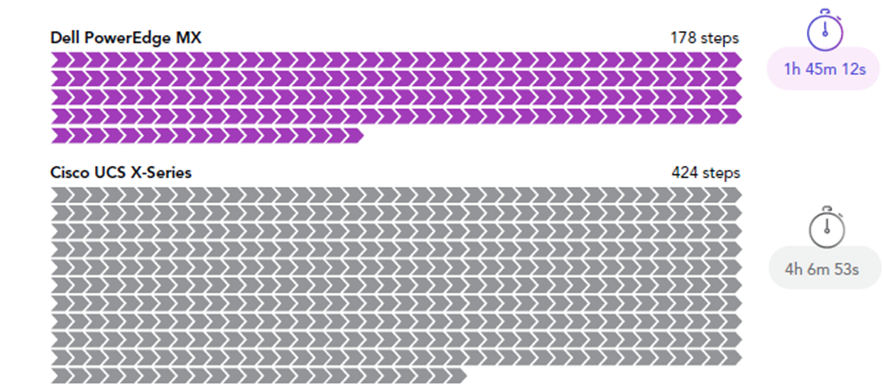
Principled Technologies testing showed customers can save significant administrator time and effort by migrating legacy UCS workloads to Dell PowerEdge MX rather than Cisco UCS X.
 By requiring 246 fewer administrator steps from initial configuration through server migration for a three-node cluster, choosing the Dell PowerEdge MX platform could help reduce human error and possible troubleshooting time as you move your new hardware into production. With PowerEdge MX, administrators save time as well—2 hours and 21 minutes for a three-node cluster—compared to moving to new Cisco UCS hardware. That is time that administrators can spend working on new initiatives to further their business goals.
Read the report here!
Related Documents

PowerEdge MX Validate Baseline to Improve Operational Efficiency


Mon, 16 Jan 2023 21:29:16 -0000
|Read Time: 0 minutes
Summary
Modern compute platforms consist of many components requiring multiple firmware elements. This can lead to complexity and risk when updating these components. To eliminate this problem for MX customers, Dell produces a biennial firmware baseline and validates the complete end-to-end stack with testing built on real customer use cases. Dell OpenManage system management orchestration then offers a simple route to update, at scale, live environments to this desired state.
This Direct from Development (DfD) tech note describes at a high level the Dell methodology for applying updates with no disruption in service. This enables lowering risk, streamlining the update process, and saving time for organizations.
Market positioning
The PowerEdge MX is a scalable modular platform comprising compute, networking, and storage elements, and designed for data center consolidation with easy deployment and rich integrated management. PowerEdge MX features an industry- leading no midplane design and scalable network fabric, within a chassis architecture to support today’s emerging processor technologies, new storage technologies, and new connectivity innovations well into the future.
PowerEdge MX firmware baseline
Reduce complexity and simplify operations by leveraging Dell’s MX validated solution infrastructure firmware baseline. This is a set of system and component firmware for
the MX platform that is rigorously tested as “one release” in a number of configurations, using the most popular operating system environments based on real world customer use cases. When the updates have passed this testing as a group, a validated solution stack firmware catalog that details the release versions is published. Several solutions in the OpenManage portfolio can then consume the catalog as an update blueprint.
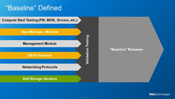 Figure 1. MX Baseline Components
Dell MX firmware baselines offer customers an elegant and automated method for platform wide updates. Advantages for customers include:
- Aggregates multiple releases into one consolidated update
- Dell end-to-end validation helps eliminate the risk of element incompatibility
- Reduces the number of maintenance windows and the amount downtime required for updating
Anatomy of the PowerEdge MX baseline
The PowerEdge MX validated solution baseline consists of many elements, including system BIOS, iDRAC, NICs, CNAs, fibre channel adapters, HBAs and other critical updates. In addition, the stack extends into the chassis to include network switch code and management controller software “OME-M”. The MX platform baseline testing includes the Chassis I/O Modules such as MX9116n, MX7116n, MX5108, and MXG610 capabilities in all forms with scaled VLANs. It also includes testing with different configurations, protocols, and workloads. For Fiber Channel and FCoE, baseline testing also includes testing scenarios in NPIV Proxy Gateway, FIP Snooping Bridge, and Direct Attached mode. An example end-to-end stack test is VMWare ESXi running on the compute sleds connected to a PowerStore storage array using FCoE Ethernet and testing updating from an old baseline to the new baseline. When the Dell updates pass evaluation, a validated solution stack of the platform firmware catalog file containing details of the tested versions is published online ready to be consumed by Dell update mechanisms, such as the update manager integrated into OME. Think of the validated baseline as a recipe for success.
When it comes to apply updates, Dell’s OpenManage system management automation provides a timesaving centralized process with intelligent safeguards to eliminate downtime. The benefits of using OME-M to perform updates using the catalog include: automatically identifying components that require updates, downloading the updates from the Dell support site, creating and scheduling update jobs, correctly ordering tasks, and reporting. The following example shows a sample catalog, highlighting the non-compliant elements. An administrator needs only to click the “Make Compliance” to start the task to update multiple elements in the MX environment.
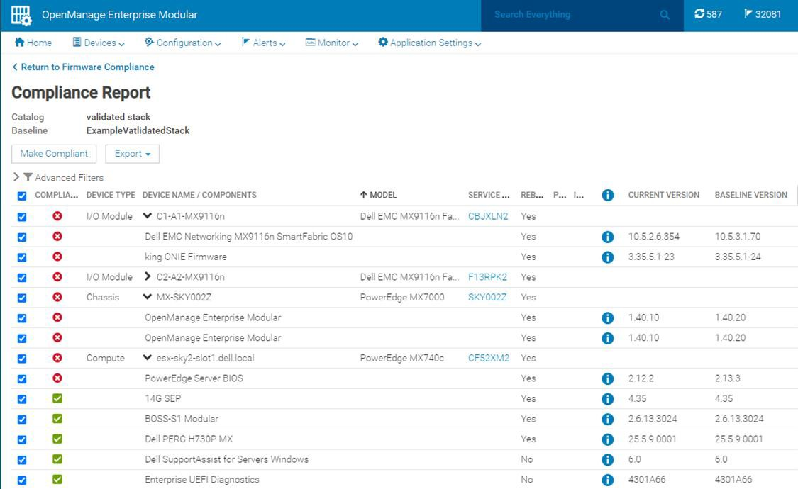
Figure 2. Detailed view of a firmware update
VMware enhancement
For customers running their VMware environment on PowerEdge MX platform, this firmware update process can be enhanced using OMEVV (OpenManage Enterprise plugin for VMware vCenter) to be “VMware cluster” aware, in order to safeguard services from outages. Cluster aware updates mean intelligent rules that allow patching only one member of a VMware cluster at a time. Leveraging ESXi maintenance mode, DRS, and vMotion, before patching a physical host,
virtual machines are systematically migrated “hot” to other ESXi hosts, ensuring that workloads and services running on the cluster are kept online at all times. After applying the updates, the host restarts and re-joins the cluster. DRS can then live migrate virtual machines back to the newly updated host. This sequence is repeated for each host in the cluster, offering a controlled rolling upgrade for the entire cluster.
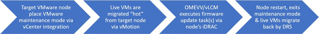
Figure 3. OMEVV/VMware host rolling updates
OMEVV also includes a scheduling engine to manage timed updates during quiet periods or to set maintenance windows. Larger customers can run parallel updates on up to 15 clusters simultaneously from a single console.
IOMs
If a customer is using an MX environment with MX9116n/MX7116n network switches in SmartFabric mode, they simply select “make compliant” from the OME-M GUI. No searching for the correct switch code, no manual upload code to the switch, it is all taken care of as part of the catalog. OME-M interfaces with switches to upload the new code. If the switches are configured as a pair, the update runs automatically on one switch at a time to ensure problem free connectivity during the updates.
RESTful API
The OpenManage Enterprise APIs enable the customer to integrate with other management products such as Ansible play books or build tools based on common programming and scripting languages, including Python and PowerShell. These APIs are fully documented. Dell posts many examples on GitHub code repository for administrators / developers to download and use for free.
In Conclusion
Customers who rely on Dell PowerEdge MX for their compute needs can streamline the update process, saving time and ensuring firmware compliance, by leveraging MX validated solution stack firmware baselines. In addition, for VMware environments, intelligent rolling firmware updates for hosts offer updating with zero service outages, and no end user downtime.
References
To learn more, see:

VMware Cloud Foundation 5.1 on next gen Dell PowerEdge servers
Thu, 16 May 2024 15:42:24 -0000
|Read Time: 0 minutes
A Principled Technologies deployment guide
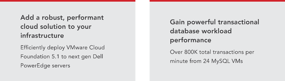
The release of VMware Cloud Foundation™ 5.1 offers new scalability, security, and enhancements that can help organizations meet essential infrastructure-as-a-service (IaaS) requirements. When backed by next gen Dell™ PowerEdge™ servers (with their own advantages in performance, security, management, and more), the VMware and Dell solution could deliver a robust, scalable, and efficient on-premises cloud infrastructure that provides the underlying infrastructure for your business to achieve your strategic business goals.
This comprehensive guide explains the deployment process for VMware Cloud Foundation 5.1 on a cluster of Dell PowerEdge servers, steps that we verified by doing the work ourselves. As your organization continues to evolve in the dynamic landscape of modern IT, this guide can empower your system administrators, architects, and IT professionals with the knowledge and expertise to implement the VMware and Dell cloud solution efficiently and effectively.
In addition to verifying the straightforward deployment process of VMware Cloud Foundation 5.1 on next gen Dell PowerEdge servers, we ran an online transaction processing (OLTP) workload on 24 VMs configured with MySQL database software. The consistent new orders per minute (NOPM) metrics that we captured demonstrate the potential transactional database performance value that the VMware and Dell cloud solution can deliver.
About 16th Generation Dell PowerEdge servers
With enhanced processing power, advanced security features, and transformative management capabilities, the 16th Generation servers can offer strong standards of server performance for your data center. According to Dell, “Whether your applications and data reside in the cloud, data centers, or edge environments, Dell’s PowerEdge portfolio empowers you to harness the full ease and agility of the cloud.”[i] Learn more about the portfolio of 16th Generation Dell PowerEdge rack, tower, purpose-built, and modular infrastructure servers.
VMware Cloud Foundation 5.1 overview
VMware Cloud Foundation (VCF) 5.1 allows your organization to build and operate a robust private or hybrid cloud infrastructure, seamlessly integrating essential resources and services into a unified platform. Boasting features such as automated lifecycle management and intrinsic security, Cloud Foundation 5.1 can simplify the deployment and management of cloud environments while ensuring efficiency.
This latest release includes security updates, fixes for UI and Lifecycle Management issues, enhancements to prechecks at the bundle level for VMware vCenter®, and several key enhancements that address requirements for cloud scale infrastructure.[ii],[iii] It provides a complete set of software-defined services for compute, storage, network, and security, along with cloud management capabilities.[iv],[v]
Learn more about VCF 5.1.
VMware Cloud Foundation components
VCF 5.1 comprises the following:
• VMware vSphere®
• VMware NSX®
• VMware vSphere with Tanzu™
• VMware ESXi™ 8.0 U1
• VMware vCenter Server® 8.0 U1
• VMware vSAN™ 8.0 U1
• VMware Aria Suite™
• VMware Cloud Builder
• VMware Software-Defined Data Center (SDDC) Manager 5.0.[vi]
VCF automates deployment and configuration of the private or hybrid cloud software stack for your virtual infrastructure. The initial VCF deployment creates a management domain that you can then use to add workload domains. Workload domains consist of clusters of at least three ESXi hosts and can manage and segregate resources and workloads in your private cloud.
For deploying and overseeing the logical infrastructure within the private cloud, VCF incorporates Cloud Builder and SDDC Manager virtual appliances to enhance VMware virtualization and management elements. These components were essential in our deployment to the next gen Dell PowerEdge server cluster.
VMware Cloud Builder automates the deployment of the management domain, the first cluster in a VCF deployment that manages the health of the VCF stack and the deployment of workload domains (server clusters that you use to run workload VMs).
SDDC Manager automates the virtualization software life cycle, encompassing configuration, provisioning, upgrades, and patching, including host firmware, while simplifying day-to-day management and operations. Through the SDDC Manager interface, which Figure 1 shows, the virtual infrastructure administrator or cloud administrator can provision new private cloud resources, monitor changes to the logical infrastructure, and oversee life cycle and other operational activities.

Figure 1: The VMware SDDC Manager interface. Source: Principled Technologies.
SDDC Manager uses vSphere Lifecycle to bundle, stage, and deploy software, OS, and firmware updates on a per-workload domain basis.
Additionally, VMware lists other features that we did not use in our deployment but that could be helpful in your next gen Dell PowerEdge cluster environment:[vii]
- vSphere with Tanzu/Workload Management integration to run Kubernetes workloads natively in vSphere
- vSAN stretched cluster configuration to provision two availability zones in a single workload domain, including a management domain, which could provide native high availability and physical resiliency and could minimize management service and workload downtime
- NSX Federation to manage network configuration across multiple VCF instances and management domains
- VMware Cloud Foundation+ to connect to VMware Cloud® using a subscription model rather than key-based component licensing and to manage your VCF instance via the VMware Cloud Console
Setting up the next gen Dell PowerEdge servers
The Dell PowerEdge servers that comprised our cluster included the following:
- Four Dell PowerEdge R750xs servers for management domain
- Three Dell PowerEdge R760 servers for virtual infrastructure workload domain
We deployed the VCF management domain on the four Dell PowerEdge R750xs servers. Each PowerEdge R750xs server had two BOSS drives for VMware ESXi 8.0.2 and eight SAS SSDs for VMware vSAN storage. The VCF management domain uses its own vCenter, NSX networking, and vSAN storage. To deploy and configure those resources and SDDC Manager automatically during the Cloud Builder deployment, VCF used our configuration details from the Deployment Parameter Workbook. This is an Excel workbook where you enter credentials, IPs, VLANs, and other configuration details for the VCF deployment and then upload it to Cloud Builder, which tests the input and allows you to continue deploying VCF once everything passes validation.
After deploying the VCF management domain, we deployed a virtual infrastructure (VI) workload domain on the three Dell PowerEdge R760 servers. Each Dell PowerEdge R760 server had two BOSS drives for ESXi 8.0.2, and four NVMe® drives and 20 SAS SSDs for vSAN storage. VI workload domains are additional vSphere clusters of at least three hosts with their own storage (in our case vSAN) and their own vCenter Server instance. VI workload domains provide physical and logical units for segregating and managing customer workloads.[viii]
All the Dell PowerEdge servers in our testbed had two 25Gb Ethernet connections to a Dell S5248F switch. We also used a Dell PowerEdge R6625 server as an infrastructure server where we deployed the AD/DNS server, the Certificate Authority server, a jumpbox VM, and routers to manage the VLANs on the Dell S5248F switch.
Overview of our VCF 5.1 deployment on a Dell PowerEdge server cluster
Figure 2 shows an example of how you can deploy all management components in VMware Cloud Foundation, which was the general process we followed.

Figure 2. Example flow chart of a VMware Cloud Foundation 5.1 deployment. Source: Principled Technologies based on VMware Deployment Overview of VMware Cloud Foundation.
You can install VCF 5.1 either “as a new release or perform a sequential or skip-level upgrade to VMware Cloud Foundation 5.1.”[ix] The new installation process, which we broadly followed, has three phases:[x]
- Preparing the environment: “The Planning and Preparation Workbook provides detailed information about the software, tools, and external services that are required to implement a Software-Defined Data Center (SDDC) with VMware Cloud Foundation, using a standard architecture model.”[xi] Note: Unlike the Deployment Parameter Workbook, an Excel file that you complete and upload to Cloud Builder, the Planning and Preparation Workbook is a long list of values, IPs, VLANs, domain names, usernames, passwords, etc. Your infrastructure team completes it with all the environment details and you use that as reference throughout the deployment process, but do not upload it at any point.
- Imaging all servers with ESXi: “Image all servers with the ESXi version mentioned in the Cloud Foundation Bill of Materials (BOM) section. See the VMware Cloud Foundation Deployment Guide for information on installing ESXi.”[xii] We installed the latest Dell-customized ESXi 8 version to each host under test at the start of testing and configured the OS as the Planning and Preparation Workbook specified.
- Installing Cloud Foundation 5.1: VMware Cloud Builder handles the bulk of the VCF deployment. Using the Planning and Preparation Workbook, in conjunction with the automation of VCF, made our deployment a smooth and almost entirely automated process. (Once you have uploaded the workbook and it passes validation with no errors, you click a button to kick off the automated deployment of the management domain.)
Key takeaway
Less-experienced infrastructure administrators might find some difficulty in setting up VMware Cloud Foundation due to the complex initial environment requirements, such as DNS, networking/IP pools, and preparing hosts and disks. In our experience, however, the validation process of the Parameter Workbook helped with troubleshooting and ensuring accuracy before our deployment. Once the software successfully validated the workbook, Cloud Builder fully automated the VCF deployment, including vSAN, NSX, vCenter, and SDDC Manager. This makes deployment much easier and faster for admins at any level rather than manually completing the same processes.
Deploying VMware Cloud Foundation 5.1 on Dell PowerEdge servers
Getting started
Note that we deployed our solution by following the steps in this document but skipped some optional steps, such as including Workspace ONE.
Prior to deploying VCF via the VMware Cloud Builder, we set up infrastructure components in our environment, including the following:
- A Windows Server 2022 VM that we configured as an Active Directory domain controller for our VCF domain (in our case, we used vcfdomain.local)
- This VM also included a DNS server with forward and reverse lookups for core infrastructure components as defined by the Planning and Preparation workbook, including fully qualified domain names (FQDNs) for SDDC Manager, vCenter, and other key components of the VCF deployment
- This VM also hosted an internal NTP server for VCF hosts
- DNS with forward and reverse lookups for all relevant DNS entries
- Another Windows Server 2022 VM that we configured as a child domain controller joined to the primary VCF domain that served as the Active Directory Certificate Services role
- SDDC Manager used this domain as an internal Certificate Authority to allow trusted communication between the various VCF components
- Other necessary infrastructure components, such as pfsense VMs to handle inter-VLAN routing, DHCP, and provide NAT to the internal network where we deployed VCF
- Configuring our Dell S5248F switch as required by the Planning Workbook
We also configured static IPs for the management domain hosts and vSAN ready disks for the management cluster.
Using the Planning and Preparation Workbook
We filled out the VCF Planning and Preparation Workbook with our environment’s details. This is a Microsoft Excel workbook that serves as a configuration guide for the required VCF components and for select components after the automated deployment. Download the Planning and Preparation Workbook.
Our environment details included our supporting virtual infrastructure and IP addresses, hostnames, credentials, and other relevant details. Some of these VMware Cloud Builder automatically configured during the deployment and others we manually configured after the deployment. As we mentioned earlier, this Planning and Preparation Workbook is different from the VCF Deployment Parameter Workbook, which we used to define the environment details for the automated VCF deployment via the Cloud Builder appliance.
Imaging the servers
After we fully populated the workbook, we followed the steps from this document to prepare the individual hosts for the management domain:
- We installed ESXi on each of the hosts. We used ESXi 8.0.2 build 22380479 (Dell Customized), the most recent Dell-customized ESXi 8 version at the time.
- We configured networking on each of the hosts. We used the ESXi direct console UI to set the network adapter, hostname, static IP address, subnet mask, gateway, and DNS as specified in the planning workbook. We also enabled SSH in troubleshooting options.
- We logged into the ESXi host client for each host and started the NTP server. We also ensured that the SSH service was running.
- After setting the hostnames, we regenerated the self-signed certificates on each host so that the common name of the certificate included the hostname. We connected to each host using SSH, regenerated the self-signed certificate, and restarted the hostd and vpxa services.
Installing VMware Cloud Builder
We then finished by populating the Deployment Parameter Workbook with our environment details, networking information, and credentials. (For more information on deploying Cloud Builder, see the guide.)
After preparing all four ESXi hosts for the management domain, we deployed the VMware Cloud Builder appliance to our infrastructure host using the ESXi host client, the Cloud Builder appliance OVA file, and specified admin and root credentials and networking details for the appliance. After we deployed Cloud Builder, we connected to the Cloud builder VM via SSH and confirmed that it could successfully ping the ESXi hosts. See this VMware document for more information.
We then logged into the VMware Cloud Builder appliance web interface by navigating to its FQDN in a web browser and following the steps listed on the web interface. The steps consisted of filling out the VCF Deployment Parameter Workbook with values from the Planning and Preparation Workbook and then uploading it to the Cloud Builder VCF deployment wizard. Cloud Builder validated the entire configuration as the Deployment Parameter Workbook specified. To learn more about the Deployment Parameter Workbook, visit https://docs.vmware.com/en/VMware-Cloud-Foundation/5.1/vcf-deploy/GUID-08E5E911-7B4B-4E1C-AE9B-68C90124D1B9.html.
After populating the Deployment Parameter Workbook with the relevant networking, existing infrastructure, credentials, and licensing information and testing that everything passed validation in the VMware Cloud Builder, we clicked Deploy SDDC and the Cloud Builder automatically deployed SDDC Manager and the other components of our initial VCF management cluster, including vCenter, NSX Manager, and vSAN.
VMware documentation states that Cloud Builder lists any issues with validation as errors or warnings in the UI. Users must address any configuration or environment errors before continuing. We did not encounter any errors or warnings in our deployment.
After validating and testing the environment parameters, the Cloud Builder appliance used our information to deploy the management domain cluster, consisting of four hosts. The deployment process included deploying a VMware vCenter Server environment, configuring NSX and vSAN, deploying SDDC Manager, and transferring control of the hosts and environment to SDDC Manager.
As we previously noted, VCF is compatible with vSphere with Tanzu workloads and Workload Management for running Kubernetes-based applications and workloads natively on the ESXi hypervisor layer. You could enable Workload Management on the management domain cluster or on specific workload domain clusters. We did not do this in our testing or use vSphere with Tanzu.[xiii]

Figure 3: The VMware Cloud Builder post-deployment success screen. Source: Principled Technologies.
Post-deployment configuration
With our core VCF components and management domain cluster deployed, we needed to complete some steps in SDDC Manager before deploying the first VI workload domain or VMware Aria Suite components.
Based on recommendations in VMware documentation,[xiv] we deployed Aria Operations after the initial management domain deployment and configured the software to provide workload and performance visibility into the VCF management domain and our eventual virtual infrastructure workload domains.
We logged into our newly deployed SDDC Manager instance and configured it to authenticate with VMware Customer Connect to download install and update bundles for Aria Suite Lifecycle Manager and the VI workload domain deployment. We also configured SDDC Manager to use our internal Certificate Authority server to manage CA-signed certificates for the physical infrastructure underlying our VCF deployment. In our management domain, we deployed an NSX Manager and Edge cluster and application virtual networks. We referenced these VMware documents.
Next, we followed the steps in this document to deploy VMware Aria Suite Lifecycle in the management domain. We used SDDC Manager to generate and sign a certificate for Lifecycle Manager by following these steps. We configured Lifecycle Manager to communicate with our management domain vCenter. We did the same for Aria Suite Operations: deployed it to our management domain for visibility into our virtual and physical infrastructure and then configured it in SDDC Manager. See how to configure Lifecycle Manager and more information on deploying Aria Suite Operations. After we installed VMware Aria Operations, the entire VCF management domain deployment was complete (see Figure 3).
Preparing for workload activity
To deploy a VI workload domain cluster, we prepared three new hosts the same way we configured the management domain ESXi hosts. We created a network pool for the workload domain cluster and commissioned them to the SDDC inventory. We then deployed the VI workload domain by following these steps. We deployed an NSX Edge cluster to the workload domain for virtual networking infrastructure and generated certificates in SDDC Manager for the VI workload domain hosts. We considered our workload domain fully configured at this point and ready for our proof-of-concept database workload.
Deploying the OLTP database workload
We used the TPROC-C benchmark from the HammerDB suite to simulate a real-world online transaction processing database workload. We created a VM running MySQL database software on the workload domain cluster with 16 vCPUs, 64 GB of memory, and 2 TB of storage from the VSAN datastore. We installed Ubuntu 22.04 and MySQL 8.0 on the VM. We then scaled out to 24 VMs on each Dell PowerEdge R760 server. We ran the HammerDB 4.9 TPROC-C workload on each VM with 500 warehouses and measured the new orders per minute.
About HammerDB
HammerDB is an open-source benchmarking tool that tests the performance of many leading databases. The benchmark tool includes two built-in workloads derived from industry standards: a transactional (TPROC-C) workload and an analytics (TPROC-H) workload. We chose the TPROC-C (TPC-C-like) workload to demonstrate the online transaction processing performance capabilities of each instance, which benefit from high core counts and fast memory. TPROC-C runs a transaction processing workload that simulates an ecommerce business with five types of transactions: receiving a customer order, recording a payment, delivering an order, checking an order’s status, and checking stock in inventory.[xv] Note that our test results do not represent official TPC results and are not comparable to official TPC-audited results. To learn more about HammerDB, visit https://www.hammerdb.com/.
Get strong cloud OLTP database performance
We ran the TPROC-C workload three times and collected the total NOPM and transactions per minute (TPM) across all 24 MySQL VMs (see Table 1). The median run is in bold.
Table 1: The total new orders per minute and transactions per minute for all 24 MySQL VMs in our testbed. Source: Principled Technologies.
TPROC-C run 1 | TPROC-C run 2 | TPROC-C run 3 | |
Total NOPM | 342,850 | 344,889 | 345,961 |
Total TPM | 796,817 | 801,329 | 803,411 |
Figure 4 shows CPU utilization during the median run (run 2). CPU utilization stayed around 70 percent during the test. We wanted to hit 70 percent utilization to simulate a real-world OLTP workload.

Figure 4: CPU utilization during the median run of our testing. Source: Principled Technologies.
Figure 5 shows the average vSAN storage latencies for the Dell PowerEdge cluster during run 2. Read latency stayed between 1.5 and 2 milliseconds, and write latency stayed 2.5 and 3 milliseconds, showing that storage access stayed relatively low and constant during for the OLTP workload.

Figure 5: Average vSAN storage latencies for the Dell PowerEdge cluster with VCF 5.1. Source: Principled Technologies.
Conclusion
Deploying VMware Cloud Foundation 5.1 on next gen Dell PowerEdge servers brings together critical virtualization capabilities and high-performing hardware infrastructure. Relying on our hands-on experience, this deployment guide offers a comprehensive roadmap that can guide your organization through the seamless integration of advanced VMware cloud solutions with the performance and reliability of Dell PowerEdge servers. In addition to the deployment efficiency, the Cloud Foundation 5.1 and PowerEdge solution delivered strong performance while running a MySQL database workload. By leveraging VMware Cloud Foundation 5.1 and PowerEdge servers, you could help your organization embrace cloud computing with confidence, potentially unlocking a new level of agility, scalability, and efficiency in your data center operations.
This project was commissioned by Dell Technologies.
May 2024
Principled Technologies is a registered trademark of Principled Technologies, Inc.
All other product names are the trademarks of their respective owners.
Read the report on the PT site at https://facts.pt/Hse6826 and see the science at https://facts.pt/vXo6g7E.
[i] Dell Technologies, “Dell PowerEdge Servers,” accessed January 3, 2024,
[ii] VMware, “VMware Cloud Foundation 5.0 Release Notes,” accessed December 20, 2023,
[iii] Rick Walsworth, “Announcing VMware Cloud Foundation 5.0,” accessed December 20, 2023,
https://blogs.vmware.com/cloud-foundation/2023/06/01/announcing-vmware-cloud-foundation-5-0/.
[iv] VMware, “VMware Cloud Foundation 5.0 Release Notes.”
[v] VMware, “VMware Cloud Foundation Overview,” accessed December 20, 2023,
[vi] VMware, “Frequently Asked Questions: VMware Cloud Foundation 5.0,” accessed December 19, 2023,
[vii] VMware, “VMware Cloud Foundation Features,” accessed February 9, 2024,
[viii] VMware, “VMware Cloud Foundation Glossary,” accessed February 9, 2024,
[ix] VMware, “VMware Cloud Foundation 5.1 Release Notes,” accessed January 3, 2024,
[x] VMware, “VMware Cloud Foundation 5.1 Release Notes.”
[xi] VMware, “VMware Cloud Foundation 5.1 Release Notes.”
[xii] VMware, “VMware Cloud Foundation 5.1 Release Notes.”
[xiii] VMware, “VMware Cloud Foundation with VMware Tanzu,” accessed February 9, 2024,
[xiv] VMware, “Unified Cloud Management for VMware Cloud Foundation,” accessed February 9, 2024,
[xv] HammerDB, “Understanding the TPROC-C workload derived from TPC-C,” accessed March 13, 2024,
https://www.hammerdb.com/docs/ch03s05.html.
Author: Principled Technologies